

Corning Optical Communication Wireless GXC85L70A17 40 User Manual

MobileAccessGX™
DAS System
Installation and Configuration Guide
P/N: 709C010701
REV: A0
Date: MAY, 2012

Preface
Corning MobileAccess
8391 Old Courthouse Road, Suite 300, Vienna, VA 22182
Tel: +1(866)436-9266, +1(703)848-0200 TAC: +1(800)787-1266, Fax: +1(703)848-0280
www.corning.com/mobileaccess
MobileAccessGX and MobileAccess are trademarks of Corning MobileAccess, Inc.
Corning MobileAccess is a trademark of Corning Incorporated.
Corning MobileAccess Inc. is a wholly-owned affiliate of Corning Incorporated.
MobileAccessGX Installation and Configuration Guide II

Preface
PPrreeffaaccee MMaatteerriiaall
© Copyright 2012, MobileAccess All Rights Reserved.
This document may contain confidential and proprietary information of Corning MobileAccess, Inc. (“MobileAccess”) and
may not be copied, transmitted, stored in a retrieval system or reproduced in any format or media, in whole or in part,
without the prior written consent of MobileAccess. Information contained in this document supersedes any previous
manuals, guides, specifications, data sheets or other information that may have been provided or made available to the
user.
This document is provided for informational purposes only, and Corning MobileAccess does not warrant or guarantee the
accuracy, adequacy, quality, validity, completeness or suitability for any purpose of the information contained in this
document. Corning MobileAccess reserves the right to make updates, improvements and enhancements to this document
and the products to which it relates at any time without prior notice to the user. CORNING MOBILEACCESS MAKES NO
WARRANTIES, EXPRESS OR IMPLIED, INCLUDING, WITHOUT LIMITATION, THOSE OF MERCHANTABILITY AND FITNESS
FOR A PARTICULAR PURPOSE, WITH RESPECT TO THIS DOCUMENT OR ANY INFORMATION CONTAINED HEREIN.
Policy for Warrantee and Repair
Corning MobileAccess tests and inspects all its products to verify their quality and reliability. Corning MobileAccess uses
every reasonable precaution to ensure that each unit meets their declared specifications before shipment. Customers
should advise their incoming inspection, assembly, and test personnel about the precautions required in handling and
testing our products. Many of these precautions can be found in this manual.
The products are covered by the following warranties:
General Warranty
Corning MobileAccess warrants to the original purchaser all standard products sold by Corning MobileAccess to be free of
defects in material and workmanship for one (1) year from date of shipment from Corning MobileAccess. During the
warranty period, MobileAccess will repair or replace any product that Corning MobileAccess proves to be defective. This
warranty does not apply to any product that has been subject to alteration, abuse, improper installation or application,
accident, electrical or environmental over-stress, negligence in use, storage, transportation or handling.
Specific Product Warranty Instructions
All Corning MobileAccess products are warranted against defects in workmanship, materials and construction, and to no
further extent. Any claim for repair or replacement of units found to be defective on incoming inspection by a customer
must be made within 30 days of receipt of shipment, or within 30 days of discovery of a defect within the warranty
period.
This warranty is the only warranty made by MobileAccess and is in lieu of all other warranties, expressed or implied.
Corning MobileAccess sales agents or representatives are not authorized to make commitments on warranty returns.
Returns
In the event that it is necessary to return any product against above warranty, the following procedure shall be followed:
1. Return authorization is to be received from MobileAccess prior to returning any unit. Advise Corning MobileAccess of
the model, serial number, and discrepancy. The unit may then be forwarded to Corning MobileAccess, transportation
prepaid. Devices returned collect or without authorization may not be accepted.
2. Prior to repair, Corning MobileAccess will advise the customer of our test results and any charges for repairing
customer-caused problems or out-of-warranty conditions etc.
MobileAccessGX Installation and Configuration Guide III

Preface
3. Repaired products are warranted for the balance of the original warranty period, or at least 90 days from date of
shipment.
Limitations of Liabilities
Corning MobileAccess's liability on any claim, of any kind, including negligence for any loss or damage arising from,
connected with, or resulting from the purchase order, contract, quotation, or from the performance or breach thereof, or
from the design, manufacture, sale, delivery, installation, inspection, operation or use of any equipment covered by or
furnished under this contact, shall in no case exceed the purchase price of the device which gives rise to the claim.
EXCEPT AS EXPRESSLY PROVIDED HEREIN, MOBILEACCESS MAKES NO WARRANTY, EXPRESSED OR IMPLIED, WITH
RESPECT TO ANY GOODS, PARTS AND SERVICES PROVIDED IN CONNECTION WITH THIS AGREEMENT INCLUDING,
BUT NOT LIMITED TO, THE IMPLIED WARRANTIES OF MERCHANTABILITY AND FITNESS FOR A PARTICULAR PURPOSE.
MOBILEACCESS SHALL NOT BE LIABLE FOR ANY OTHER DAMAGE INCLUDING, BUT NOT LIMITED TO, INDIRECT,
SPECIAL OR CONSEQUENTIAL DAMAGES ARISING OUT OF OR IN CONNECTION WITH FURNISHING OF GOODS, PARTS
AND SERVICE HEREUNDER, OR THE PERFORMANCE, USE OF, OR INABILITY TO USE THE GOODS, PARTS AND SERVICE.
Reporting Defects
The units were inspected before shipment and found to be free of mechanical and electrical defects.
Examine the units for any damage that may have been caused in transit. If damage is discovered, file a claim with the
freight carrier immediately. Notify Corning MobileAccess as soon as possible.
NOTE: Keep all packing material until you have completed the inspection
RF Safety
NOTE: Keep all packing material until you have completed the inspection
WARNING: To comply with FCC RF exposure compliance requirements, antennas used for this product must be fixed
mounted on indoor permanent structures, providing a separation distance of more than 300 cm from all persons during
normal operation.
WARNING: Antenna gain should not exceed 10 dBi.
WARNING: Each individual antenna used for this transmitter must be installed to provide a separation distance greater
than 300 cm or more from all persons and must not be co-located with any other antenna for meeting RF exposure
requirements.
WARNING: The design of the antenna installation needs to be implemented in such a way so as to ensure RF radiation
safety levels and non-environmental pollution during operation.
MobileAccessGX Installation and Configuration Guide IV
Preface
WARNING! To comply with FCC RF exposure compliance requirements, antennas used for this product
must be fixed mounted on indoor permanent structures, providing a separation greater than 300 cm
from all persons during normal operation.
Comment [R1]: Removed following
section
Safety Instructions
Installation Safety Guidelines
Follow all safety regulations when installing the GX system
Only qualified personnel are authorized to install and maintain the GX system
The equipment is intended for installation in restricted access locations only
RF Safety
1. Each individual antenna used for this transmitter must be installed to
provide a separation distance greater than 300 cm or more from all persons
and must not be co-located with any other antenna for meeting RF
exposure requirements.
2. The design of the antenna installation needs to be implemented in such a
way so as to ensure RF radiation safety levels and non-environmental
pollution during operation.
Compliance with RF safety requirements:
Corning MobileAccess products have no inherent significant RF radiation.
The RF level on the downlink is very low at the downlink ports. Therefore, there is no
dangerous RF radiation when the antenna is not connected.
Laser Safety
THE LASER APERTURES /OUTPUTS ARE THE GREEN SC/APC BULKHEAD ADAPTERS LOCATED ON THE FRONT PANEL OF THE
EQUIPMENT.
THE PRODUCT IS CLASS 1/HAZARD LEVEL 1
FIBER OPTIC PORTS OF THE MOBILEACCESS FT-350 EMIT INVISIBLE LASER RADIATION AT THE 1310/1550 NM WAVELENGTH
WINDOW.
EXTERNAL OPTICAL POWER IS LESS THAN 10 MW, INTERNAL OPTICAL POWER IS LESS THAN 500 MW.
TO AVOID EYE INJURY NEVER LOOK DIRECTLY INTO THE OPTICAL PORTS, PATCHCORDS OR OPTICAL CABLES. DO NOT STARE INTO
BEAM OR VIEW DIRECTLY WITH OPTICAL INSTRUMENTS. ALWAYS ASSUME THAT OPTICAL OUTPUTS ARE ON.
ONLY TECHNICIANS FAMILIAR WITH FIBER OPTIC SAFETY PRACTICES AND PROCEDURES SHOULD PERFORM OPTICAL FIBER
CONNECTIONS AND DISCONNECTIONS OF THE MOBILEACCESS FT-350 DEVICES AND THE ASSOCIATED CABLES.
THE MOBILEACCESS FT-350 COMPLIES WITH 21 CFR 1040.10 AND 1040.11 EXCEPT FOR DEVIATIONS PURSUANT TO LASER
NOTICE NO. 50 (2007).
THE FT-350 EMPLOYS A CLASS 3B LASER AND THEREFORE THE FOLLOWING LABEL IS AFFIXED INSIDE THE UNIT ADJACENT TO THE
LASER:
MobileAccessGX Installation and Configuration Guide V
Preface
CAUTION – USE OF CONTROLS OR ADJUSTMENTS OR PERFORMANCE OF PROCEDURES OTHER THAN
THOSE SPECIFIED HEREIN MAY RESULT IN HAZARDOUS RADIATION EXPOSURE
THE PRODUCT ITSELF HAS BEEN TESTED AND CERTIFIED AS A CLASS 1 LASER PRODUCT TO IEC/EN 60825-1 (2007). IT ALSO
MEETS THE REQUIREMENTS FOR A HAZARD LEVEL 1 LASER PRODUCT TO IEC/EN 60825-2: 2004 TO THE SAME DEGREE.
Care of Fiber Optic Connectors
DO NOT REMOVE THE PROTECTIVE COVERS ON THE FIBER OPTIC CONNECTORS UNTIL A CONNECTION IS READY TO BE MADE. DO
NOT LEAVE CONNECTORS UNCOVERED WHEN NOT CONNECTED.
THE TIP OF THE FIBER OPTIC CONNECTOR SHOULD NOT COME INTO CONTACT WITH ANY OBJECT OR DUST.
REFER TO THE CLEANING PROCEDURE FOR INFORMATION ON THE CLEANING OF THE FIBER TIP.
Warnings and Admonishments
Radio Frequency Energies
THERE MAY BE SITUATIONS, PARTICULARLY FOR WORKPLACE ENVIRONMENTS NEAR HIGH-POWERED RF SOURCES, WHERE RECOMMENDED LIMITS
FOR SAFE EXPOSURE OF HUMAN BEINGS TO RF ENERGY COULD BE EXCEEDED. IN SUCH CASES, RESTRICTIVE MEASURES OR ACTIONS MAY BE
NECESSARY TO ENSURE THE SAFE USE OF RF ENERGY.
High Voltage
THE EQUIPMENT HAS BEEN DESIGNED AND CONSTRUCTED TO PREVENT, AS FAR AS REASONABLY, PRACTICABLE DANGER. ANY WORK ACTIVITY ON
OR NEAR EQUIPMENT INVOLVING INSTALLATION, OPERATION OR MAINTENANCE MUST BE, AS FAR AS REASONABLY, FREE FROM DANGER.
WHERE THERE IS A RISK OF DAMAGE TO ELECTRICAL SYSTEMS INVOLVING ADVERSE WEATHER, EXTREME TEMPERATURES, WET, CORROSIVE OR
DIRTY CONDITIONS, FLAMMABLE OR EXPLOSIVE ATMOSPHERES, THE SYSTEM MUST BE SUITABLY INSTALLED TO PREVENT DANGER.
Protective Earthing
EQUIPMENT PROVIDED FOR THE PURPOSE OF PROTECTING INDIVIDUALS FROM ELECTRICAL RISK MUST BE SUITABLE FOR THE PURPOSE AND
PROPERLY MAINTAINED AND USED.
Handling Precautions
THIS COVERS A RANGE OF ACTIVITIES INCLUDING LIFTING, LOWERING, PUSHING, PULLING, CARRYING, MOVING, HOLDING OR RESTRAINING AN
OBJECT, ANIMAL OR PERSON FROM THE EQUIPMENT. IT ALSO COVERS ACTIVITIES THAT REQUIRE THE USE OF FORCE OR EFFORT, SUCH AS PULLING
A LEVER, OR OPERATING POWER TOOLS.
WHERE SOME OF THE ABOVEMENTIONED ACTIVITIES ARE REQUIRED, THE EQUIPMENT MUST BE HANDLED WITH CARE TO AVOID BEING DAMAGED
Electrostatic Discharge (ESD)
MobileAccessGX Installation and Configuration Guide VI

Preface
OBSERVE STANDARD PRECAUTIONS FOR HANDLING ESD -SENSITIVE DEVICES. ASSUME THAT ALL SOLID-STATE ELECTRONIC DEVICES ARE ESD-
SENSITIVE. ENSURE THE USE OF A GROUNDED WRIST STRAP OR EQUIVALENT WHILE WORKING WITH ESD-SENSITIVE DEVICES. TRANSPORT,
STORE, AND HANDLE ESD-SENSITIVE DEVICES IN STATIC-SAFE ENVIRONMENTS.
MobileAccessGX Installation and Configuration Guide VII

Preface
US
Radio Equipment and Systems
FCC 47 CFR part 22 – for CELL Frequency Band
FCC 47 CFR part 27 – for 700 LTE and AWS Frequency Bands
EMC
FCC 47 CFR part 15 Subpart B
NOTE: This equipment has been tested and found to comply with the limits for a
Class A digital device, pursuant to Part 15 of the FCC Rules. These limits are
designed to provide reasonable protection against harmful interference in a
residential installation. This equipment generates, uses and can radiate radio
frequency energy and, if not installed and used in accordance with the instructions ,
may cause harmful interference to radio or television reception, which can be
determined by turning the equipment off and on, the user is encouraged to try to
correct the interference by one or more of the following measures:
- Reorient or relocate the receiving antenna.
- Increase the separation between the equipment and receiver.
-Connect the equipment into an outlet on a circuit different from that to which the
receiver is connected.
-Consult the dealer or an experienced radio/TV technician for help.
Warning!
Changes or modifications to this equipment not expressly approved by Mobile
Access could void the user’s authority to operate the equipment.
Safety
UL 60950
CAN/CSA-C22.2 No.60950
Laser Safety
CDRH 21 CFR 1040.10, 1040.11 (Except for deviations per notice No.50, July 26, 2001)
IEC 60825-1, Amendment 2 (January 2001)
EN 60825-1
Standards and Certification
Corning MobileAccess products have met the approvals of the following certifying organizations:
Company Certification
ISO 9001: 2000 and ISO 13485: 2003
Product Certifications
About this Guide and Other Relevant Documentation
Additional Relevant Documents
MobileAccessGX Installation and Configuration Guide VIII
This Installation Guide describes how to perform the physical installation of the M obileAccessGX
unit. The installation procedures of other units (e.g. RIU, FT-350 OCH, SC-450) relevant to the
system are detailed in their user manuals (see
Additional Relevant Documentation
below).

Preface
Document Name
RIU Installation and Configuration Guide
FT-350 Installation Guide
SC-450 Installation and Configuration Guide
MA Software Version Update Tool
BDA
Bi-Directional Amplifier
BTS
Base Transceiver Station
BTSC
Base Transceiver Station Conditioner
BU
Base Unit
DL
Downlink
GXGX
Higher Power Transmission
RIU
Radio Interface Unit
UL
Uplink
The following documents are required if the corresponding units are included in your system.
List of Acronyms
MobileAccessGX Installation and Configuration Guide IX

Table of Contents
Preface Material ................................................................................................................................ III
Policy for Warrantee and Repair ......................................................................................................... III
Safety Instructions ............................................................................................................................. V
Warnings and Admonishments ........................................................................................................... VI
Standards and Certification .............................................................................................................. VIII
About this Guide and Other Relevant Documentation ........................................................................ VIII
List of Acronyms ............................................................................................................................... IX
Table of Contents................................................................................................................................X
1 Introduction to GX System ................................................................ ................................ 1
1.1 Features and Capabilities .............................................................................................................. 2
1.2 System Architecture ..................................................................................................................... 3
1.2.1 Signal Path......................................................................................................................... 4
1.2.1.1 SISO Signal Path .................................................................................................... 4
1.2.1.2 MIMO Signal Path ................................................................................................... 4
1.3 System Monitoring and Management............................................................................................. 4
1.4 GX Unit Interfaces ....................................................................................................................... 6
2 System Installation ............................................................................................................ 8
2.1 Site Considerations ...................................................................................................................... 8
2.1.1 Installation Location ........................................................................................................... 8
2.1.2 Environmental .................................................................................................................... 8
2.1.3 Powering ........................................................................................................................... 8
2.1.4 Grounding Requirement ...................................................................................................... 8
2.1.5 Cable Routing .................................................................................................................... 9
2.1.6 Manual Handling ................................................................................................................ 9
2.2 Installation Requirements ............................................................................................................. 9
2.3 Fiber Optic Rules ......................................................................................................................... 9
2.4 Assembling Radome on GX – TBD ............................................................................................... 10
2.5 Assembling External Filter (If Required) ...................................................................................... 10
2.6 Installing the GX Unit ................................................................................................................. 11
2.6.1 Unpacking and Inspection ................................................................................................. 11
2.6.2 Required Tools ................................................................................................................. 12
2.6.3 Mounting ......................................................................................................................... 12
2.6.3.1 Wall Mount Installation ......................................................................................... 12
2.6.3.2 Pole Mount Installation ......................................................................................... 14
2.7 GX Connections ......................................................................................................................... 17
2.7.1 Grounding Connections ..................................................................................................... 17
2.7.2 F/O Connections ............................................................................................................... 18
MobileAccessGX Installation and Configuration Guide X

Preface
2.7.3 RF Connections ................................................................................................................ 19
2.7.4 Power Connections ........................................................................................................... 20
2.8 Verifying Normal Operation ........................................................................................................ 21
LED .......................................................................................................................................... 21
Description .............................................................................................................................. 21
RUN .......................................................................................................................................... 21
Flashing Green - ...................................................................................................................... 21
Flashes green for the duration of a minute upon system initialization ............................... 21
Off - .......................................................................................................................................... 21
System initialized .................................................................................................................... 21
FSK .......................................................................................................................................... 21
Flashing Green - ...................................................................................................................... 21
Flashes (rate of flash per second) for the duration of 1 minute upon communication
initialization ............................................................................................................................. 21
Rapid/No Flash - ...................................................................................................................... 21
Indicates communication fault ............................................................................................... 21
ALM ................................................................................................................................ .......... 21
Steady Red - ............................................................................................................................ 21
Fault ......................................................................................................................................... 21
Off - .......................................................................................................................................... 21
Normal operation .................................................................................................................... 21
3 Commissioning MA Head-End ........................................................................................ 22
3.1 Initial Controller Setup ............................................................................................................... 22
3.1.1 Open a Session to the Controller ....................................................................................... 22
3.1.2 IP Address Configuration .................................................................................................. 24
3.2 Configure Controller Settings ...................................................................................................... 26
3.3 Device Configuration and Preparation.......................................................................................... 26
3.4 RIU Configuration ...................................................................................................................... 28
3.4.1 Configuration for all BTSCs (other than LTE 700) ................................................................ 28
MobileAccessGX Installation and Configuration Guide XI

Preface
3.4.2 BTSC LTE 700 MHz ........................................................................................................... 29
3.5 OCH Configuration Dialog ........................................................................................................... 32
4 Provisioning the MobileAccessGX ................................................................................. 34
4.1 Accessing GX Management Options ............................................................................................. 34
4.2 Basic Setup Procedure ................................................................................................................ 35
Appendix A: System Specifications ...................................................................................... 40
Appendix B: Ordering Information ........................................................................................ 43
Appendix C: Site Preparation ................................................................................................. 44
Installation Requirements .................................................................................................................. 44
Coaxial Cable Connections ................................................................................................................. 44
Power Consumption, Connections and Power Supplies ........................................................................ 46
Installation Conventions .................................................................................................................... 47
MobileAccessGX Installation and Configuration Guide XII
11
IInnttrroodduuccttiioonn ttoo GGXX SSyysstteemm
MobileAccessGX offers a scalable, cost-effective 20/40W (43/46dBm) high power remote
outdoor coverage solution for Corning MobileAccess Distributed Antenna Systems (DAS). It is a
fiber-fed, compact, multi-service, multi-operator remote designed to complement the
MobileAccess1000 and MobileAccess2000 lower power, standard remotes or installable as a
dedicated deployment solution in a new site, providing complete RF coverage options for open
indoor, tunnel and adjacent outdoor spaces in larger venues such as stadiums, convention
centers, metro-rails and malls.
GX supports multiple wireless technologies and operator services over a single broadband
infrastructure. Using low loss fiber optic cabling, GX remote units can cover distances between 215km from the BTS signal sources at the head -end.
Front-end wireless RF services are routed over optic fibers to GX series remote units, which are
securely located at each remote location. These modular service aggregation platforms precisely
combine multiple wireless service signals for simultaneous distribution over a common
broadband infrastructure. GX supports all major modulations in mixed mode with high efficiency
and linear MCPA up to 40W.
The solution can be deployed in new sites or alongside existing MobileAccess1000 (MA1000)
and/or MobileAccess2000 (MA2000) remotes, sharing a common head-end and element
management system (EMS).
High, RF power coverage capabilities and compact, space saving, weather resistant design
ensures optimal coverage for various site needs .
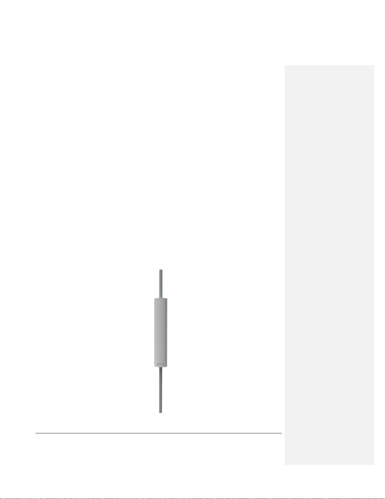
Figure 1-1.
MobileAccessGX Installation and Configuration Guide 1
MobileAccessGX - Radome Covered Pole Mounted GX Units

1.1 Features and Capabilities
Multi-Frequency/Multi-Service RF Transport Platform: Accommodates GSM, UMTS,
HSPA, LTE, EDGE, EV-DO, and more. Three model-dependent bands per enclosure.
Scalable: Expandable tri-band to up to six bands.
MIMO support: 2x2 MIMO configuration for LTE700, AWS and UMTS bands
Cost-Effective Higher Power: Optimizes and reduces the number of antennas required to
cover open and outdoor areas by offering 43dBm or 46dBm (GX-20/40) composite power
per frequency band.
Operator-Grade Operation: Advanced signal handling and management ensure s
operator-grade performance.
Unique, space-saving non-obtrusive design: Blends into the environment and avoids
costly tower builds outdoors when covering campus scenarios, parking lots, tunnels and
indoor-adjacent outdoor space.
Designed to withstand harsh environments - Fully sealed weatherproof remote unit,
provides superior performance in harsh environments and worry -free electronics
maintenance. Compliant to IP65/NEMA standard.
Management and control – alarm forward to NOC or standard EMS via SNMP, software
controlled output power and Optical link auto gain control
MobileAccessGX Installation and Configuration Guide 2
1.2 System Architecture
MobileAccessGX provides a complete solution consisting of GX remote units at the remote
locations, and head-end elements, which are shared with any existing or new MA1000/MA2000
deployment.
In the downlink, at the head-end, the BTS or BDA signal is conditioned by the RIU, ensuring a
constant RF level. The conditioned signal is then converted by the FT-350 OCH (Optical Control
Hub) to an optical signal for transport over single-mode fiber to the GX remote units, which are
located at the remote locations. In the uplink, the process is reversed. The SC-450 Controller
enables local and remote management, as well as controls all GX, MA1000 and MA2000
elements from a single, centralized location.
The MobileAccessGX Remote Unit consists of a uniquely designed, non-obtrusive unit that
includes all of the required RF, F/O and power interfaces. The GX product supports four service
types: CELL/PCS/LTE 700/AWS – each unit supports up to 3 bands, whereas the supported
bands depend on model (see Appendix B: Ordering Information). All mobile services are
distributed through service/band dedicated RF connection ports over antennas installed at the
remote locations.
Figure 1-2. System Architecture
NOTE: When MobileAccess GX unit is deployed with units supporting the 800MHz band, an
external filter is needed to be installed on the GX to avoid the disturbance between the 800MHz
DL and the 850MHz UL frequencies.
MobileAccessGX Installation and Configuration Guide 3
OCH
GX
RIU
To DAS antennas
F/O
To signal source
RF
OCH
GX
RIU
RIU
GX
To DAS antennas
F
/
O
F
/
O
To signal source –
MIMO 1 path
To signal source –
MIMO 2 path
RF
RF
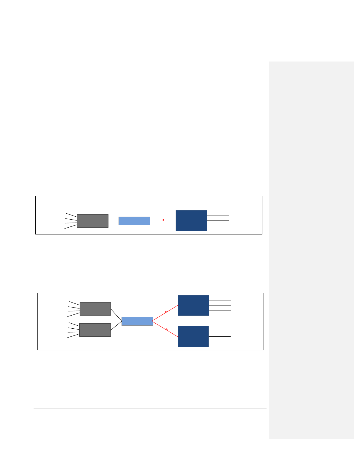
1.2.1 Signal Path
1.2.1.1 SISO Signal Path
On the DL, combined signals up to tri-band from the OCH converted into optical signals. Then
the optical signals are transmitted to the RU via optical fiber. The Optical TX/RX Module of RU
converts the DL optical signals into RF signals. After filtering signal for each band and
amplification, the signals are transmitted at the output port (700MHz/CELL850/PCS/AWS) to the
service antenna.
On the UL, the signals transmitted by the mobile are converted into optical signals, and then via
the UL optical fiber. The signals are transmitted to OCH, which then converts the optical signals
back to RF signals.
The optical DL and UL signal are transmitted in a single optical fiber based on WDM technique.
Figure 1-3. GX Functional Block Diagram – SISO Configuration
1.2.1.2 MIMO Signal Path
In MIMO system, the principle is similar to the single system. In MIMO, Dual-DL and dual-UL are
required, e.g. 700LTE / AWS. So two GX remote units are connected to the OCH. A pair of
optical fiber in same length is needed for the remote units to ensure the same time delay to both
units.
Figure 1-4. GX Functional Block Diagram – MIMO Configuration
1.3 System Monitoring and Management
The MobileAccessGX Remote Unit is centrally managed via the MobileAccess SC-450 Controller.
Note that MobileAccessGX is not connected directly to the controller. It is connected to the FT-
MobileAccessGX Installation and Configuration Guide 4
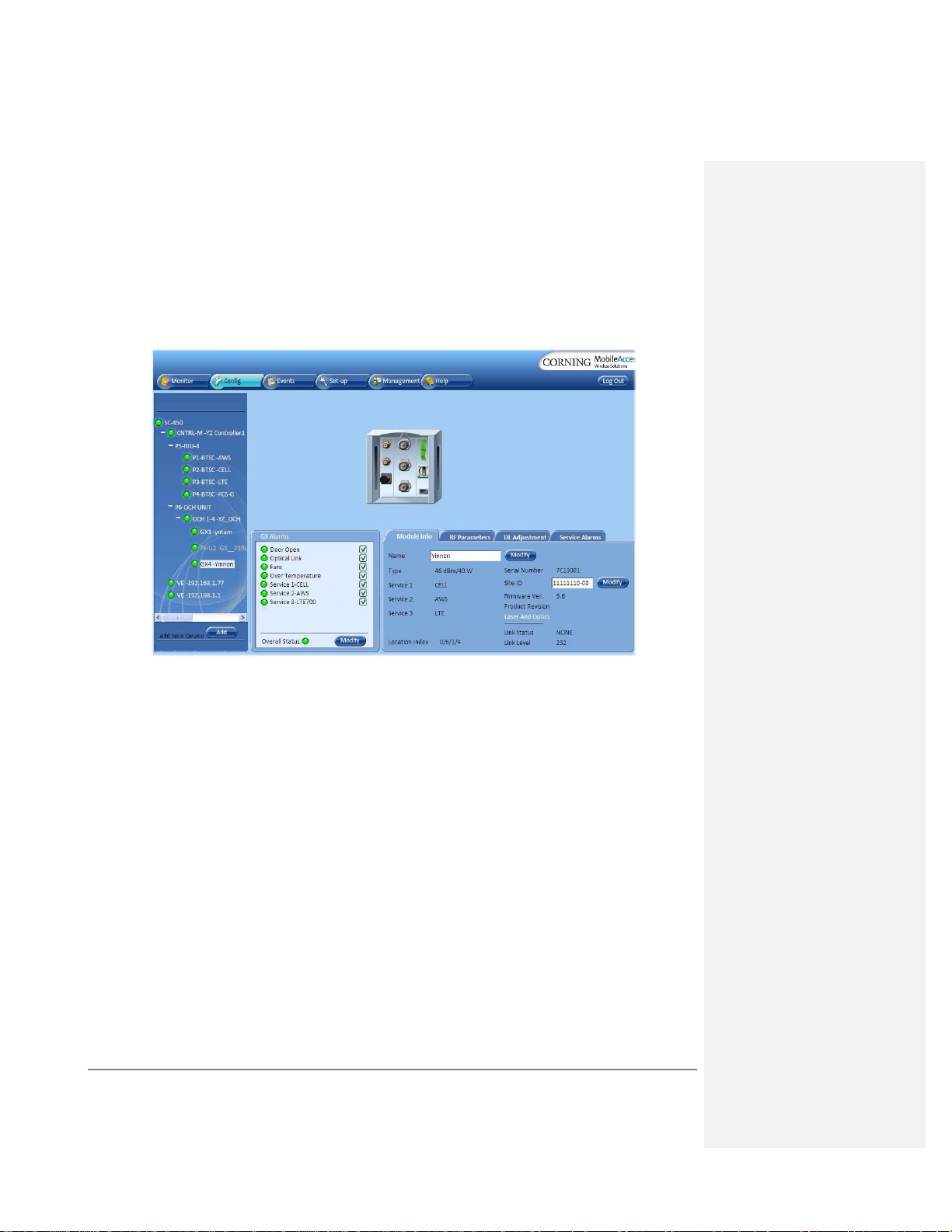
350 OCH element (that is connected to the controller). Thus, the controller monitors views and
manages the GX via the OCH to which the GX is connected.
The following shows the Config(uration) tab of the selected GX unit. The system configuration
and management is described in Chapter 4.
Figure 1-5: Example of GX Configuration Tab
MobileAccessGX Installation and Configuration Guide 5
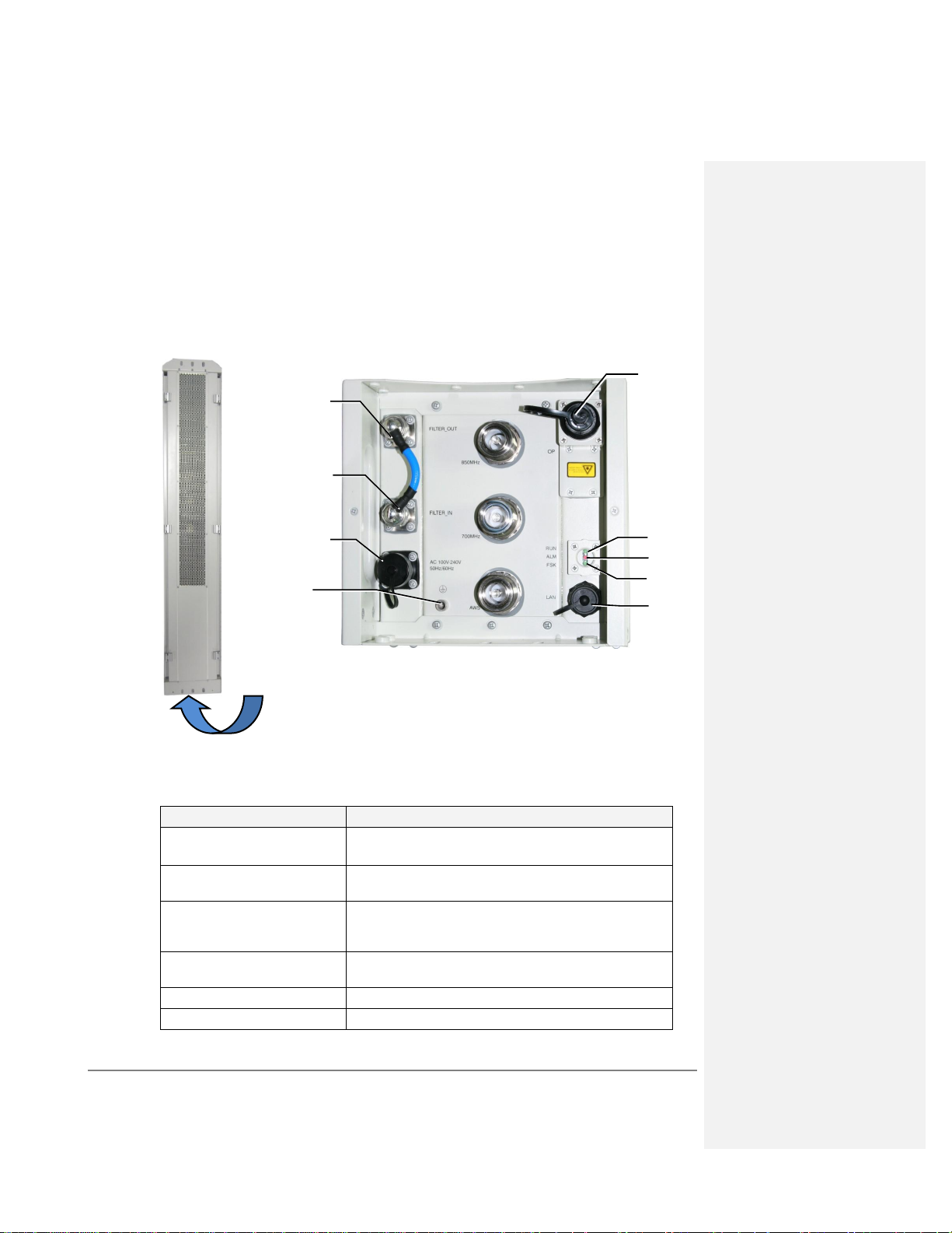
Figure 1-6: GX Interfaces – Underside Panel
Connector
Description
Service Connectors
(e.g. 850MHz, 700MHz, AWS)
DIN female connectors to antennas
OP
SC/APC optical fiber access port (waterproof) connection
to OCH for either SM or MM fibers.
AC
Remote Power (AC) Power feed options: 100-240 V AC
50Hz/60Hz
Max Power Consumption: 1400W
LAN
RJ45 connector for local connection (i.e. debugging,
troubleshooting)
EXT_ALM
N/A
FILTER_ IN/ FILTER_ OUT
Connections to external filter
Connectors located
on underside panel
Filter In port
AC power
port
OP port
Filter Out port
RF Service connector
RF Service connector
RF Service connector
RJ45 LAN
connector
RUN LED
Grounding
ALMLED
FSK LED
1.4 GX Unit Interfaces
All of the GX interfaces are located externally on the underside of the unit (facing down when
unit is mounted). The unit interfaces include the RF, power and optical link connectors.
The following tables provide a description of the GX connectors and LEDs.
MobileAccessGX Installation and Configuration Guide 6
Table 1-1. Connector Descriptions
 Loading...