

Page 1

Corning
ONE™ Wireless Platform
User Manual
APRIL 2013
Page 2

Preface Material
P/N 709C011801
Page 2
Preface Material
About This Manual
This user guide provides all the information necessary to understand the architecture and perform the installation of
Corning® ONE™ Wireless Platform.
Hardware
Corning warrants to the original purchaser (“Customer”) that for the duration of the warranty period, one (1) year,
commencing on the date of shipment of the Hardware, unless otherwise agreed in writing by Corning (the “Hardware
Warranty Period”), the Hardware furnished by Corning shall be free in all material respects from defects in material
and workmanship, and shall conform to the applicable portions of the Specifications, as defined below (the
“Hardware Warranty”).
If notified by Customer of any such defects in material or workmanship or nonconformity with applicable portions of
the Specifications within the Hardware Warranty Period, Corning shall promptly, at its own election and expense,
repair or replace any such Hardware proven to be defective under the terms of this Hardware Warranty.
Such repair or replacement shall be Customer’s sole remedy and Corning sole obligation in the event this Hardware
Warranty is invoked. If any components comprising a part of the Hardware are replaced or repaired during the
Hardware Warranty Period, the Hardware Warranty Period for such repaired or replaced components shall extend to
the longer of (i) the balance of the Hardware Warranty Period or (ii) three (3) months from the date of repair or
replacement. For purposes of this Warranty, “Specifications” shall mean the specifications and performance
standards of the Products as set forth in documents published by Corning and delivered to Customer which contain
technical specifications or performance standards for the Products.
If Customer invokes this Hardware Warranty, it shall notify Corning promptly of the claimed defect.
Customer will allow Corning to inspect the Hardware at Customer’s location, or to return the Hardware to Corning
closest repair facility. For Hardware returned to Corning repair facility, Customer shall be responsible for payment of
all transportation and freight costs (including insurance) to Cornings’ repair facility, and Corning shall be responsible
for all transportation and freight costs (including insurance) incurred in connection with the shipment of such
Hardware to other repair facilities of Corning and/or its return to Customer.
Notwithstanding the foregoing, in no event will Corning be liable for damage to Products resulting from improper
handling during or after shipment, misuse, neglect, improper installation, operation or repair (other than by
authorized Corning personnel), alteration, accident, or for any other cause not attributable to defects in materials or
workmanship on the part of Corning. Corning shall not reimburse or make any allowance to Customer for any labor
charges incurred by Customer for replacement or repair of any goods unless such charges are authorized in advance
in writing by Corning.
Page 3

Preface Material
P/N 709C011801
Page 3
Software Warranty
Corning warrants to the original purchaser (“Customer”) that for the duration of the warranty period, one (1) year,
commencing on the date of shipment of the Software, unless otherwise agreed in writing by Corning (the “Software
Warranty Period”), the Software shall conform with, and perform the functions set forth in the Specifications, and
shall be free from defects in material or workmanship (the “Software Warranty”). In the event the Software is proven
to be defective under the terms of this Software Warranty, Corning shall correct such defects or failure and ensure
that the Software conforms with, and performs the functions set forth in, the Specifications. Customer will allow
Corning to inspect the Software at Customer’s location or to return it to Cornings’ closest repair facility.
Notwithstanding the foregoing, Corning shall have no obligation under the Software Warranty if the
Software is modified or used with hardware or software not supplied or approved by Corning or if the Software is
subject to abuse, improper installation or application, accident, electrical or environmental over-stress, negligence in
use, storage, transportation or handling.
Third-party software distributed with the Software may carry certain warranties which, to the maximum extent
allowed by law, Corning hereby assigns, transfers and otherwise conveys to Customer, provided, however, that
Corning itself provides no warranty of any kind, express, implied, statutory or otherwise, for any third-party software
provided hereunder.
Corning does not warrant any hardware, software or services not provided by Corning.
THIS WARRANTY IS THE ONLY WARRANTY MADE BY CORNING AND IS IN LIEU OF ALL OTHER
WARRANTIES, EXPRESS OR IMPLIED INCLUDING, BUT NOT LIMITED TO, THE IMPLIED
WARRANTIES OF MERCHANTABILITY AND FITNESS FOR A PARTICULAR PURPOSE. CORNING
SHALL NOT BE LIABLE FOR ANY OTHER DAMAGE INCLUDING, BUT
NOT LIMITED TO, INDIRECT, SPECIAL OR CONSEQUENTIAL DAMAGES ARISING OUT OF OR
IN CONNECTION WITH FURNISHING OF GOODS, PARTS AND SERVICE HEREUNDER, OR THE
PERFORMANCE, USE OF, OR INABILITY TO USE THE GOODS, PARTS AND SERVICE.
CORNING SALES AGENTS OR REPRESENTATIVES ARE NOT AUTHORIZED TO MAKE
COMMITMENTS ON WARRANTY RETURNS.
Returns
In the event that it is necessary to return any product against above warranty, the following procedure shall be
followed:
1. Return authorization is to be received from Corning prior to returning any unit. Advise Corning of the model,
Serial number, and discrepancy. The unit may then be forwarded to Corning, transportation prepaid. Devices
returned collect or without authorization may not be accepted.
2. Prior to repair, Corning will advise the customer of our test results and any charges for repairing customer-caused
problems or out-of-warranty conditions etc.
3. Repaired products are warranted for the balance of the original warranty period, or at least 90 days from date of
shipment.
Page 4

Preface Material
P/N 709C011801
Page 4
Limitations of Liabilities
Corning’s liability on any claim, of any kind, including negligence for any loss or damage arising from, connected
with, or resulting from the purchase order, contract, quotation, or from the performance or breach thereof, or from the
design, manufacture, sale, delivery, installation, inspection, operation or use of any equipment covered by or
furnished under this contact, shall in no case exceed the purchase price of the device which gives rise to the claim.
Except as expressly provided herein, Corning makes no warranty, expressed or implied, with respect to any goods,
parts and services provided in connection with this agreement including, but not limited to, the implied warranties of
merchantability and fitness for a particular purpose. Corning shall not be liable for any other damage including, but
not limited to, indirect, special or consequential damages arising out of or in connection with furnishing of goods,
parts and service hereunder, or the performance, use of, or inability to use the goods, parts and service.
Reporting Defects
The units were inspected before shipment and found to be free of mechanical and electrical defects. Examine the
units for any damage that may have been caused in transit. If damage is discovered, file a claim with the freight
carrier immediately. Notify Corning as soon as possible in writing.
N ote: Keep all packing material until you have completed the inspection
Page 5

Warnings and Admonishments
P/N 709C011801
Page 5
Warnings and Admonishments
There may be situations, particularly for workplace environments near high-powered RF sources, where
recommended limits for safe exposure of human beings to RF energy could be exceeded. In such cases, restrictive
measures or actions may be necessary to ensure the safe use of RF energy.
The equipment has been designed and constructed to prevent, as far as reasonably, practicable danger. Any work
activity on or near equipment involving installation, operation or maintenance must be, as far as reasonably, free
from danger.
Where there is a risk of damage to electrical systems involving adverse weather, extreme temperatures, wet,
corrosive or dirty conditions, flammable or explosive atmospheres, the system must be suitably installed to prevent
danger.
Equipment provided for the purpose of protecting individuals from electrical risk must be suitable for the purpose
and properly maintained and used. This covers a range of activities including lifting, lowering, pushing, pulling,
carrying, moving, holding or restraining an object, animal or person from the equipment. It also covers activities that
require the use of force or effort, such as pulling a lever, or operating power tools.
Where some of the abovementioned activities are required, the equipment must be handled with care to avoid being
damaged.
Observe standard precautions for handling ESD-sensitive devices. Assume that all solid-state electronic devices are
ESD-sensitive. Ensure the use of a grounded wrist strap or equivalent while working with ESD-sensitive devices.
Transport, store, and handle ESD-sensitive devices in static-safe environments.
RF Safety
To comply with FCC RF exposure compliance requirement, adhere to the following warnings:
Warning! Antennas used for this product must be fixed mounted on indoor permanent structures, providing a separation
distance of at least 50 cm from all persons during normal operation.
Warning! Each individual antenna used for this transmitter must be installed to provide a minimum separation distance of 50 cm
or more from all persons and must not be co-located with any other antenna for meeting RF exposure requirements.
Warning! Antenna gain should not exceed 12.5 dBi.
Warning! The design of the antenna installation needs to be implemented in such a way so as to ensure RF radiation safety
levels and non-environmental pollution during operation.
Page 6
Company Certification
P/N 709C011801
Page 6
ATTENTION!
Compliance with RF safety requirements:
• Corning products have no inherent significant RF radiation
• The RF level on the downlink is very low at the downlink ports. Therefore, there is no dangerous RF radiation
when the antenna is not connected.
CAUTION!
Use of controls, adjustments or performance of procedures other than those specified herein may result in hazardous
radiation exposure.
Laser Safety
• Fiber optic ports of the ONE™ system emit invisible laser radiation at the 1310/1550 nm wavelength window.
• External optical power is less than 10 mW, Internal optical power is less than 500 mW.
• To avoid eye injury never look directly into the optical ports, patchcords or optical cables. Do not stare into beam
or view directly with optical instruments. Always assume that optical outputs are on.
• Only technicians familiar with fiber optic safety practices and procedures should perform optical fiber
connections and disconnections of ONE™ devices and the associated cables.
• ONE™ has been tested and certified as a Class 1 Laser product to IEC/EN 60825-1 (2007). It also meets the
requirements for a Hazard Level 1 laser product to IEC/EN 60825-2: 2004 to the same degree.
• ONE™ complies with 21 CFR 1040.10 and 1040.11 except for deviations pursuant to Laser Notice NO. 50
(2007).
• ONE™ employs a Class 3B laser and therefore the following label is affixed inside the unit adjacent to the laser:
Care of Fiber Optic Connectors
• Do not remove the protective covers on the fiber optic connectors until a connection is ready to be made. Do not
leave connectors uncovered when not connected.
• The tip of the fiber optic connector should not come into contact with any object or dust.
• Refer to the cleaning procedure for information on the cleaning of the fiber tip.
Company Certification
ISO 9001: 2000 and ISO 13485: 2003
Page 7

Table of Contents
P/N 709C011801
Page 7
TTaabbllee ooff CCoonntteennttss
Preface Material ................................................................................................................................................... 2
About This Manual ................................................................................................................................................. 2
Hardware ............................................................................................................................................................... 2
Software Warranty ................................................................................................................................................. 3
Returns .................................................................................................................................................................. 3
Limitations of Liabilities .......................................................................................................................................... 4
Reporting Defects .................................................................................................................................................. 4
Warnings and Admonis hments........................................................................................................................... 5
RF Safety ............................................................................................................................................................... 5
Laser Safety ........................................................................................................................................................... 6
Care of Fiber Optic Connectors .............................................................................................................................. 6
C ompany C ertification ......................................................................................................................................... 6
Table of Contents ................................................................................................................................................. 7
1 Introduc tion ................................................................................................................................................. 13
1.1 About ONE™ ................................................................................................................................................ 13
1.2 Key Features and Capabilities ....................................................................................................................... 14
1.3 General System Specifications and Requirements ........................................................................................ 14
1.3.1 Supported Browsers ............................................................................................................................. 14
1.3.2 Environmental and Regulatory Specifications ...................................................................................... 14
1.3.2.1 Temperature and Humidity ..................................................................................................... 14
1.3.2.2 Safety and Regulatory Approvals ........................................................................................... 15
1.3.3 Power Consumption of Units ................................................................................................................ 15
1.3.3.1 General Power Safety Instructions ......................................................................................... 15
1.3.4 Dimensions and Weight of Units .......................................................................................................... 16
1.3.5 Optical Specifications ........................................................................................................................... 16
1.3.6 Default Network and User Settings ...................................................................................................... 17
1.3.6.1 Default Network Parameters ................................................................................................... 17
1.3.6.2 System Administrator or "Super User" .................................................................................... 17
1.3.6.3 Default Group Admin .............................................................................................................. 17
Page 8

Table of Contents
P/N 709C011801
Page 8
1.4 Installation Guidelines ................................................................................................................................... 18
1.4.1 Rack Mount Procedure ........................................................................................................................ 18
1.4.1.1 General Instructions ............................................................................................................... 18
1.4.1.2 Rack Installation Safety Instructions ....................................................................................... 19
1.4.2 Power Consumption, Connections and Power Supplies ....................................................................... 19
1.4.2.1 Power Safety Instructions ....................................................................................................... 19
1.4.2.2 Types of Power Supplies ........................................................................................................ 19
1.4.2.3 Circuit Breakers ...................................................................................................................... 19
1.5 System Architecture and Topologies ............................................................................................................. 20
1.5.1 RF Path ................................................................................................................................................ 20
1.5.2 Digital Path .......................................................................................................................................... 21
1.6 ONE™ WEB Management Application .......................................................................................................... 21
1.6.1 Overall Device Display - Configuration Tab .......................................................................................... 23
1.6.2 Session Access .................................................................................................................................... 23
1.7 User Controlled Sectorization ........................................................................................................................ 24
1.7.1 MIMO Configurations ........................................................................................................................... 25
1.7.2 Single Sector Example ......................................................................................................................... 25
1.7.3 Dual Sector Example ........................................................................................................................... 26
1.7.4 Tri-sector Example ............................................................................................................................... 26
1.7.5 Tri-sector Example with Two HEUs ...................................................................................................... 27
2 Unit Descriptions - R F Path ........................................................................................................................ 29
2.1 RF Path - Headend Components .................................................................................................................. 29
2.1.1 HEU (Headend Unit) ............................................................................................................................ 29
2.1.1.1 HCM (Headend Control Module) ............................................................................................ 30
2.1.1.2 RIM/RIM-M (RF Interface Module) .......................................................................................... 31
2.1.1.3 RIX (RF Expander Module) .................................................................................................... 33
2.1.1.4 PSM (Power Supply Module) .................................................................................................. 33
2.1.2 OIU (Optical Interface Unit) .................................................................................................................. 34
2.1.2.1 ACM (Auxiliary Control Module).............................................................................................. 35
2.1.2.2 OIM (Optical Interface Module) ............................................................................................... 36
Page 9

Table of Contents
P/N 709C011801
Page 9
2.1.2.3 OIX (Optical Expander Module) .............................................................................................. 37
2.2 RF Path Remote End Site Components ........................................................................................................ 38
2.2.1 ICU (Intermediate Centralized Unit) ..................................................................................................... 38
2.2.2 RAU (Remote Antenna Unit) ................................................................................................................ 39
2.2.2.1 RxU (Remote Expansion Unit) ................................................................................................ 40
3 Unit Descriptions - Digita l Path .................................................................................................................. 41
3.1 Digital Path Components ............................................................................................................................... 41
3.2 CEU (Centralized Ethernet Unit) ................................................................................................................... 41
3.2.1 CEM (Centralized Ethernet Module) ..................................................................................................... 42
3.3 GEM (Gigabit Ethernet Module) .................................................................................................................... 43
3.4 GEU-S (GEM Standalone) ............................................................................................................................ 44
4 Ins tallation – R F P ath E lements ................................................................................................................. 45
4.1 RF Headend Installation ................................................................................................................................ 45
4.1.1 HEU Installation ................................................................................................................................... 45
4.1.2 Example of HEU Master-Slave Installation ........................................................................................... 47
4.1.3 OIU Installation .................................................................................................................................... 47
4.2 RF Remote-End Installation .......................................................................................................................... 48
4.2.1 ICU Installation ..................................................................................................................................... 48
4.2.1.1 General Information ................................................................................................................ 48
4.2.2 RAU Installation ................................................................................................................................... 49
4.2.2.1 General Information ................................................................................................................ 49
4.2.3 RxU Installation .................................................................................................................................... 50
4.2.3.1 General Information ................................................................................................................ 50
5 Ins tallation – Digital Coverage E lements ................................................................................................... 51
5.1 CEU Installation ............................................................................................................................................ 51
5.2 GEM .............................................................................................................................................................. 52
5.2.1 GEM Installations with RAU Module ..................................................................................................... 52
5.2.2 GEU-S Installations .............................................................................................................................. 53
6 Commis sioning the Sys tem ....................................................................................................................... 55
6.1 Opening a Local Session .............................................................................................................................. 55
6.2 Configuring HCM Network Settings for Local and Remote Management ....................................................... 57
6.2.1 Default Network Parameters ................................................................................................................ 59
Page 10

Table of Contents
P/N 709C011801
Page 10
6.2.2 Ping Tool - Verifying IP Host Access .................................................................................................... 60
6.3 Required Pre-Setup Procedures ................................................................................................................... 61
6.4 Running the Setup Procedure ....................................................................................................................... 63
6.5 System Adjustment Procedure ...................................................................................................................... 73
6.6 About the Setup Tool .................................................................................................................................... 74
6.6.1 Overview of Setup Procedure .............................................................................................................. 75
6.6.2 Default Values Assigned in Setup Tool ................................................................................................ 76
6.6.3 Navigating the Setup Tool .................................................................................................................... 76
6.6.3.1 Module Owner ........................................................................................................................ 78
6.6.3.2 Zone Information .................................................................................................................... 79
6.6.3.3 MIMO-SETUP ........................................................................................................................ 81
6.6.3.4 RF Path .................................................................................................................................. 82
6.6.3.5 Max Input ............................................................................................................................... 84
6.6.3.6 ALC ........................................................................................................................................ 84
6.6.3.7 UL Gain .................................................................................................................................. 85
6.6.3.8 AGC ....................................................................................................................................... 87
6.6.3.9 Adjustment ............................................................................................................................. 89
7 Device Configuration .................................................................................................................................. 91
7.1 System Management (HCM) ......................................................................................................................... 93
7.2 HEU Configuration ........................................................................................................................................ 94
7.2.1 HEU ACM ............................................................................................................................................ 94
7.2.2 RIM ...................................................................................................................................................... 95
7.3 OIU Configuration ......................................................................................................................................... 97
7.3.1 OIU ACM ............................................................................................................................................. 97
7.3.2 OIM ...................................................................................................................................................... 98
7.4 RAU Configuration ........................................................................................................................................ 99
7.5 RxU Configuration ....................................................................................................................................... 101
7.6 Removing a Hosted Device from Baseline .................................................................................................. 103
8 Adminis tration ........................................................................................................................................... 105
8.1 Management Menu Tab .............................................................................................................................. 105
8.2 Multi User Account Management ................................................................................................................ 106
8.2.1 Defining User Groups ......................................................................................................................... 107
8.2.2 Defining User Accounts ...................................................................................................................... 109
Page 11

Table of Contents
P/N 709C011801
Page 11
8.2.3 Group Users Access Levels ............................................................................................................... 111
8.2.4 Modifying Passwords ......................................................................................................................... 112
8.2.4.1 System Admin Password Change ........................................................................................ 112
8.2.4.2 Group Admin Password Change .......................................................................................... 113
8.2.4.3 User Own Password Change ............................................................................................... 115
8.2.5 Session Timeout Settings................................................................................................................... 116
8.3 Backup & Restore Configurations ............................................................................................................... 117
8.4 Generating Device Reports ......................................................................................................................... 118
8.5 Activity Log .................................................................................................................................................. 120
8.6 Firmware Upgrade ...................................................................................................................................... 121
9 Monitoring and Troubles hooting ............................................................................................................. 123
9.1 Overview ..................................................................................................................................................... 123
9.2 Network Topology Tree - Fault Sourcing ..................................................................................................... 124
9.3 Fault Sourcing through the Device View and Alarms Tab ............................................................................ 126
9.3.1 HCM (System Management) Device View and Alarms ....................................................................... 126
9.3.2 ACM Device Alarms and View ........................................................................................................... 127
9.3.3 RIM Module Device View and Alarms ................................................................................................ 129
9.3.4 OIM Device View and Alarms ............................................................................................................. 130
9.3.5 RAU Device View and Alarms ............................................................................................................ 131
9.3.6 RxU View ........................................................................................................................................... 132
9.4 Masking Irrelevant Alarms ........................................................................................................................... 133
9.5 Events Display ............................................................................................................................................ 134
9.5.1 Filtering Displayed Events .................................................................................................................. 135
Page 12

Table of Contents
P/N 709C011801
Page 12
10 S NMP Management ................................................................................................................................... 137
10.1 SNMP Destination Address Configuration .......................................................................................... 137
10.2 Modifying the Read/Write Community Parameters ............................................................................. 138
10.3 SNMP Management using any Third Party SNMP Manager .............................................................. 138
10.4 Loading the MIB Files ........................................................................................................................ 139
10.5 Viewing the Traps .............................................................................................................................. 139
10.6 Binding Table ..................................................................................................................................... 140
10.7 Monitoring the Managed System ........................................................................................................ 141
10.8 List of Traps ....................................................................................................................................... 142
Appendix A: S pecifications ............................................................................................................................. 145
Supported Services ............................................................................................................................................ 145
RF Parameters per Service ................................................................................................................................ 145
Environmental, Standards and Optical ............................................................................................................... 146
Unit Specifications ............................................................................................................................................. 147
RF Coverage Component Specifications ............................................................................................ 147
Digital Coverage Component Specifications ...................................................................................... 150
Ordering Information .......................................................................................................................................... 153
HEU Chassis and Modules ................................................................................................................ 153
OIU Chassis and Modules .................................................................................................................. 153
Remote Units ..................................................................................................................................... 154
Digital Path Units ............................................................................................................................... 154
Accessories........................................................................................................................................ 154
Page 13
Introduction
P/N 709C011801
Page 13
1 Introduction
1.1 About ONE™
The Optical Network Evolution Platform (ONE™) by Corning provides a flexible in-building RF and network digital coverage
solution based on a fiber optic transport backbone.
The fiber-optics infrastructure is easily deployable via a wide range of pre-terminated composite cables and advanced
end-to-end equipment. Easy to design, Plug and Play™ connectors, significantly reduce installation cost and deployment time.
The ONE™ solution is an ideal fit for large, high-rise or campus-style deployments. It generates significant CAPEX savings and
OPEX savings through the use of user configurable sectorization and an infrastructure that is simple to deploy and efficient in
usage.
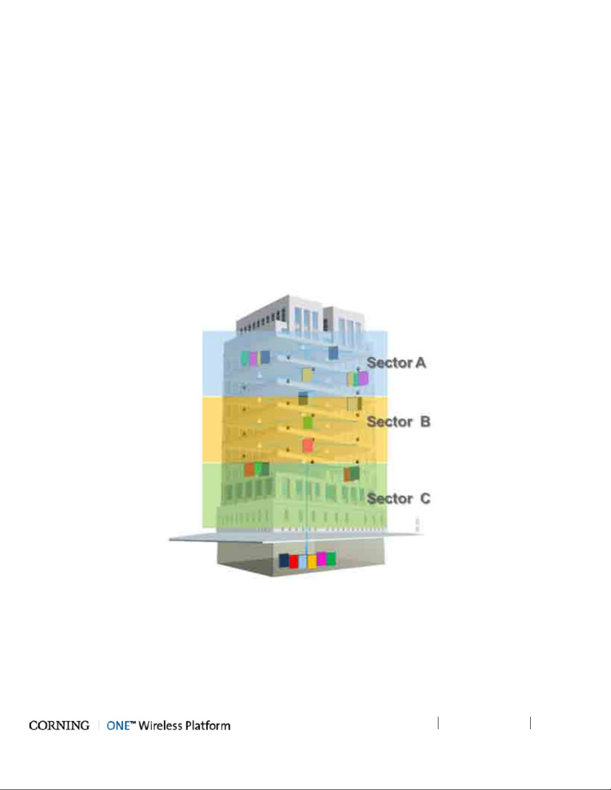
Dynamic sectorization management allows precise service distribution control to meet changing density needs, and provides
further savings by enabling sharing of equipment at various levels for service providers.
Radio source agnostic, remote units can be used as network extenders. Ethernet capability with dedicated fiber link for Wi-Fi
offload brings a higher level of granularity and support for devices and applications with very high speed requirements.
Figure 1-1. Illustration of Precise Service Distribution over Selected Remote Areas
Page 14
Introduction
P/N 709C011801
Page 14
1.2 Key Features and Capabilities
• Comprehensive Service Support - SISO/MIMO services. Currently – CELL, PCS, LTE700 and AWS
• Flexible, user controlled sectorization - Advanced capacity and coverage management for better macro offload and
enhanced user experience.
• Broadband enabled:
• A range of ready-made fiber-optic (and power) composite cables simplify installation at all levels.
• Fiber backbone unleashes unlimited RF Spectrum
• Easy scales to higher speeds requirements
• Ethernet Support - Dedicated fiber link for Ethernet backhaul, enables optimal use and offload of Wi-Fi resources.
• Scalable and customizable - Infrastructure can be quickly expanded to support more services or increase coverage
without downtime
• Carrier Grade Network Management:-
• Single-source, remote end-to-end field upgradable platform.
• Ready for SON, HetNet and future network requirements.
1.3 General System Specifications and Requirements
1.3.1 Supported Browsers
ONE™ system Web GUI Management has been optimized to operate on the following browsers:
• Microsoft Internet Explorer v7.0 and higher
• Mozilla Firefox v3.2 and higher
• Sun Solaris Mozilla
• Google Chrome 8.0 and higher
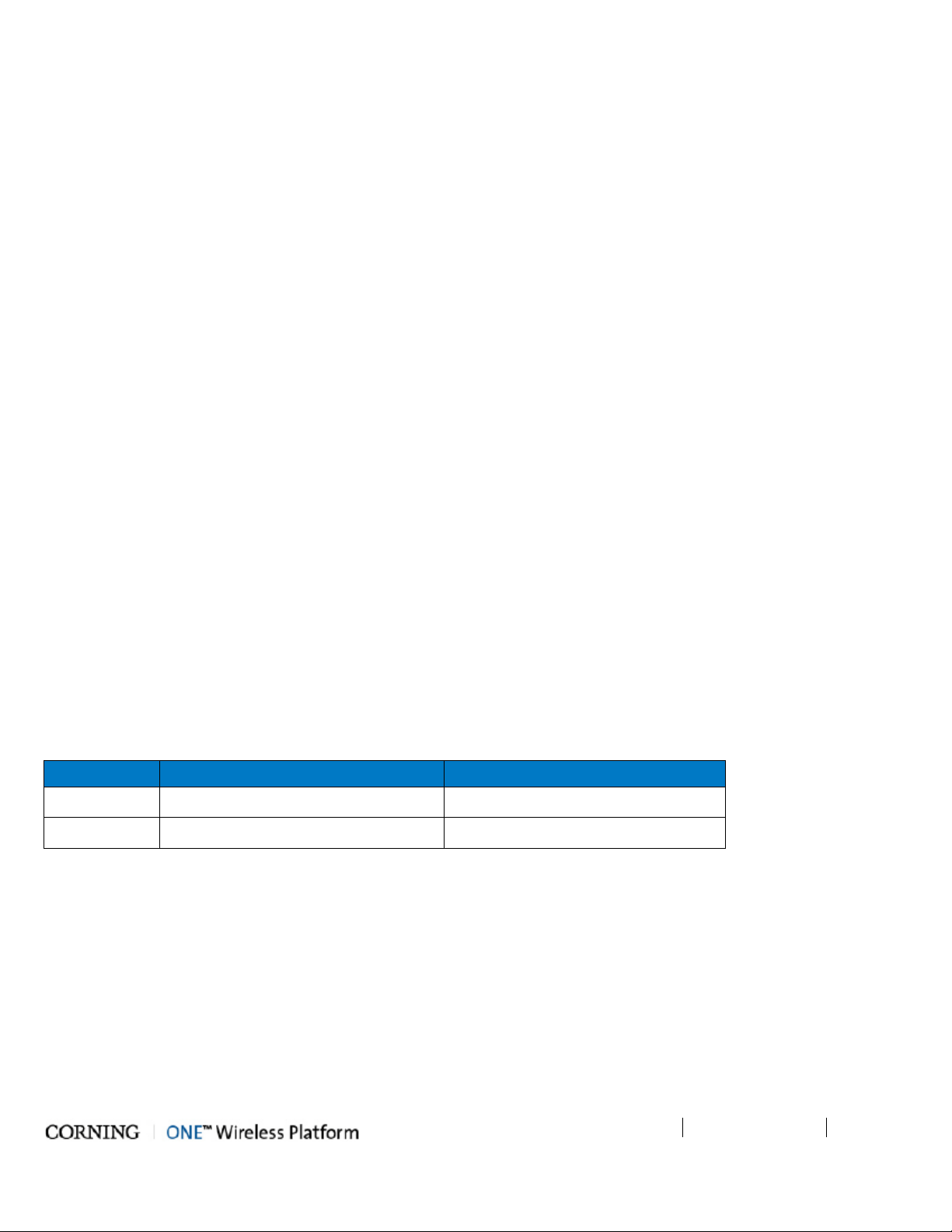
1.3.2 Environmental and Regulatory Specifications
1.3.2.1 Temperature and Humidity
The environmental specifications listed below are relevant to all ONE™ solution devices.
Operating Storage
Temperature 0°C to +50°C (32°F to 122°F) -20 C to 85 C (-4°C to 185°C)
Humidity 95% (non-condensing) 95% (non-condensing)
Table 1-1. Temperature and Humidity Specifications
Page 15
Introduction
P/N 709C011801
Page 15
1.3.2.2 Safety and Regulatory Approvals
The safety and regulatory specifications listed below are relevant to all ONE™ devices.
Regulation/Standard
Approval
Category
Laser Safety
EMC
FDA/CE 21 CFR 1040.10 and 1040.11 except for deviations pursuant to laser notice no.
50 (July 26, 2001) and IEC 60825-1, Amendment 2 (January 2001)
CE EN 301 489, EN55022, EN 61000
FCC 47 CFR Part 15, 22, 24, 27
UL 60950
Safety
CAN/CSA-C22.2 No.60950-1-03
Fire Safety UL 2043 (Applicable for Antenna Unit Only)
Table 1-2. Safety and Regulatory Approvals
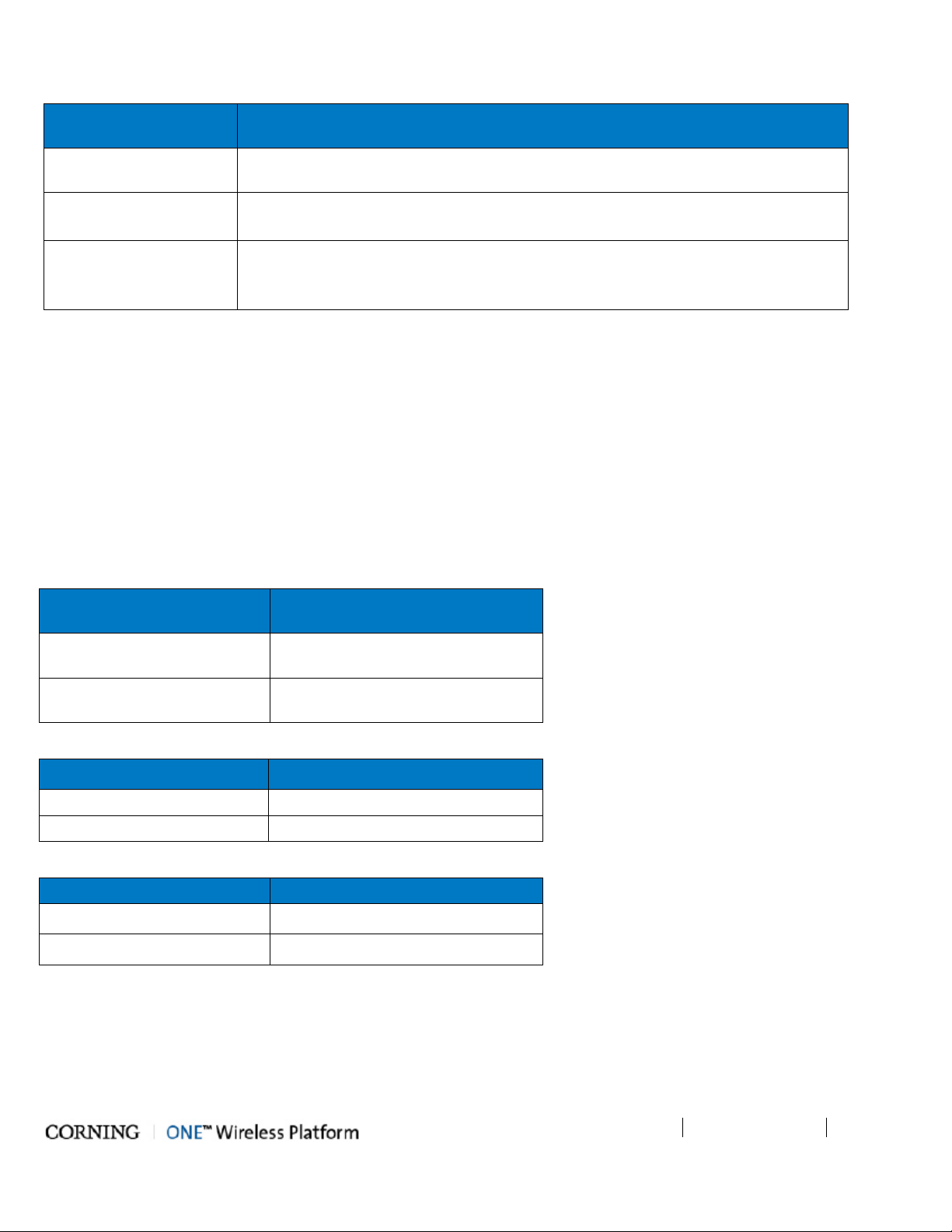
1.3.3 Power Consumption of Units
This section summarizes to power requirements of all ONE™ RF and digital coverage devices.
1.3.3.1 General Power Safety Instructions
• Use only UL approved power supplies.
• Use only the power cables (AC and DC) and any other relevant accessories provided with the unit to connect the power
supply to the ONE™ units.
• All devices connect to 110 to 240VAC power source.
RF Head End Units
HEU
Power Consumption for Full
Chassis
Chassis with 12 RIMs and 2 RIX:
200W
OIU
Chassis with 12 OIMs and 2 OIX:
300W
Table 1-3. RF Headend Units Power Consumption
RF Remote End Units Max. Power Consumption
RAU (alone) 31W
RxU 21.5W
Table 1-4. RF Remote End Units Power Consumption
Digital Remote End Units Power Consumption
GEM installed in RAU 4.5W
GEM installed in Docking station 4.5W
Table 1-5. Digital Path Remote End Power Specifications
Page 16

Introduction
P/N 709C011801
Page 16
1.3.4 Dimensions and Weight of Units
1.28 x 3.79 x 5.95 in [32.7 x 96.3 x 151.3 mm]
The tables below describe the physical specifications of the ONE™ units.
Table 1-6. RF Path Headend Units
Unit
Dimensions (H x W x D) US
Weight: lbs [kg]
[International]
HEU
7 x 17.3 x 18.95 in [177.8 x 440 x 481.7 mm]
Chassis: 37 lbs [16.8 kg]
Per RIM: 1.9 lbs [0.9 kg]
Per RIX: 1.54 lbs [0.7 kg]
HCM: 2.2 lbs [1.0 kg]
PSM: 1.98 lbs [0.9 kg]
OIU
7 x 17.3 x 18.95 in [177.8 x 440 x 481.7 mm]
Chassis: : 37 lbs [16.8 kg]
Per OIM: 0.7Kg [1.5lbs]
Per OIX: 1.54 lbs [0.7 kg]
ACM: 2.2 lbs [1.0 kg]
PSM: 1.98 lbs [0.9 kg]
Table 1-7. RF Path Remote Units
Unit
Dimensions (H x W x D) US
Weight: lbs [kg]
[International]
ICU 17 x 15 x 19.2 in [430.5 x 379.8 x 488 mm] 5.5 lbs [2.5 kg] – without PSM
RAU (including
mounting bracket)
13.1 x 13.1 x 4 in [332.7 x 332.7 x 101.6 mm]
RAU only = 7.05 lbs [3.2Kg];
RAU+RxU+GEM = 14 lbs [5.5 Kg]
Table 1-8. Digital Path Units
Unit
Dimensions (H x W x D) US
Weight: lbs [kg]
[International]
GEM
GEU-S
5.01 x 10.51 x 3.26 in (including mounting
1.1 lbs [0.5 kg]
2.64 lbs [1.2 kg]
bracket) [127.5 x 267 x 83 mm]
1.3.5 Optical Specifications
Parameter Specification
Optical Output Power <9 dBm
Max. Optical Budget 5 dB
Optical Connector
Fiber Type Corning SMF-28 or Compatible
Wavelength
Maximum Distance (headend to remote end) 2Km (SMF)
Table 1-9. Optical Specifications
OIM: MTP connector
RAU: LC/APC SM
1310±10nm (Standard)
Page 17
Introduction
P/N 709C011801
Page 17
1.3.6 Default Network and User Settings
1.3.6.1 Default Network Parameters
The following table identifies the default settings for each of the Network Ethernet ports located on the front panel of the HCM.
Port Name Configuration
DHCP: off
LOCAL
LAN
Internal
Table 1-10. Default Network Port Parameters
1.3.6.2 System Administrator or "Super User"
One System Administrator or "Super User" is available. This user has the highest access level, does not belong to any group and
is the only user that can create groups.
IP: 193.168.1.1
Subnet Mask: 255.255.0.0
DHCP: Client, or Static IP (default)
IP: 192.168.1.1
Subnet Mask: 255.255.0.0
DHCP: server on (this local port is set by default set to act as a DHCP Server and provide an
IP address to the connected computer so no configuration of the computer is required)
IP: 11.0.0.1
Subnet Mask: 255.0.0.0
NOTE: Upon initial login, the System Administrator should create user groups. Each new group created along with a default
Group Administrator.
User Name admin (cannot be modified)
Password default provided by Corning (and should be changed immediately)
Group none (leave blank)
Table 1-11. User Default Info
1.3.6.3 Default Group Admin
Groups can only be created by the Admin user. As a group is created, a default Group Administrator is automatically generated
for that group. The Group Administrator User Name and Password are based on the group name. For example, if the group is
named 'accounting', the default Group Administrator name will be accounting_Admin (note capital ‘A’ in Admin).
The Group Administrator is authorized to create and manage the users for his/her group. See section group passwords for
detailed description of default group_ Admin user.
Page 18
Introduction
P/N 709C011801
Page 18
1.4 Installation Guidelines
The following installation assumes that site survey and installation planning (including power requirements) have been
completed. This includes planning the distribution of antennas to provide the required coverage, as well as planning the layout
of the devices and cables in the telecom closet or shaft.
1.4.1 Rack Mount Procedure
These guidelines are relevant to the system components which are installed in 19-in communication racks:
• RF Path components: HEU, OIU and ICU
• Digital Coverage components: CEU
1.4.1.1 General Instructions
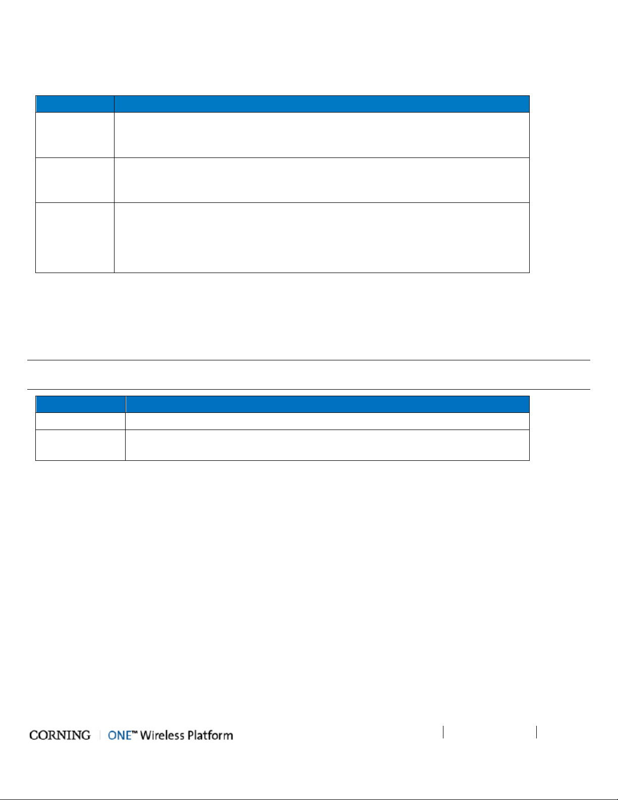
Verify that the rack height can support all the units to be installed, where you may also want to consider future installations. The
figure below illustrates the recommended physical location of the headend elements in the rack, so as to facilitate and simplify
the cabling connections.
NOTE: The configuration is for a single operator. If the site is serviced by more than one operator, each operator often installs
their equipment in a separate rack.
Figure 1-2. Example of Communication rack Installation
Page 19

Introduction
P/N 709C011801
Page 19
1.4.1.2 Rack Installation Safety Instructions
The following guidelines help ensure your safety and protect the equipment from damage during the installation.
• Only trained and qualified personnel should be allowed to install or replace this equipment.
• Verify that ambient temperature of the environment does not exceed 50°C (122°F)
• If installed in a closed or multi-unit rack, the ambient temperature of the rack environment must be taken into consideration
in terms of exceeding the maximum rated ambient temperature (indicated in the previous item).
• To maintain a low center of gravity, ensure that heavier equipment is installed near the bottom of the rack and load the rack
from the bottom to the top.
• Ensure that adequate airflow and ventilation within the rack and around the installed components so that the safety of the
equipment is not compromised. It is recommended to allow for at least about 2 cm of airspace between devices in the rack.
• Verify that the equipment is grounded as required – especially the supply connections.
1.4.2 Power Consumption, Connections and Power Supplies
1.4.2.1 Power Safety Instructions
SAFETY WARNINGS!!!! When installing or selecting the power supplies:
• Be sure to disconnect all power sources before servicing.
• Calculate the required power according to the requirements of the specific installation and then determine the configuration
of the power supplies. The required DC cables will then be determined by the selected PS configuration.
• Use only UL approved power supplies
• Install external over-current protective devices for the system according to the requirements described in Power
Consumption of Units section (on page 15).
1.4.2.2 Types of Power Supplies
CMA supplies various power supplies that can be installed in a rack or mounted on a wall, depending on your configuration.
1.4.2.3 Circuit Breakers
Calculate the required fuse protection while referring to Power Consumption of Units section (on page 15). Also, when
Install fuse protections for the system taking into account that there may be other CMA system elements that require external
fuse protection.
Page 20
Introduction
P/N 709C011801
Page 20
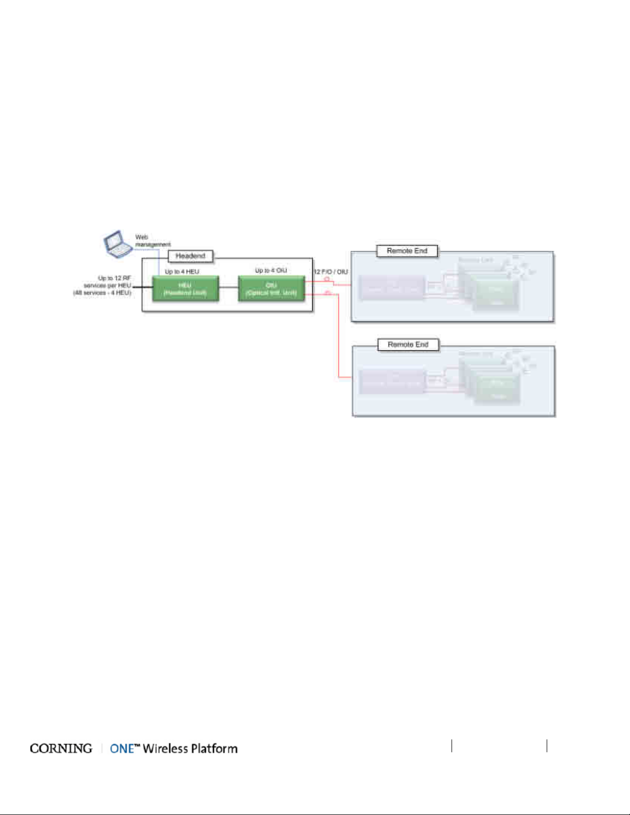
1.5 System Architecture and Topologies
The ONE™ solution fiber-optic infrastructure is used to transmit both RF and digital services:
• RF services – fiber-optics infrastructure transfers converged wireless services from the headend towards Remote Antenna
Units (RAU) deployed at the remote end locations according to user defined configuration.
• Digital services – fiber-optics infrastructure transfers Digital services from the corporate LAN to Gigabyte Ethernet Modules
(GEM) and then 3
Figure 1-3. ONE™ Solution Basic Architecture
rd
party equipment deployed on each floor.
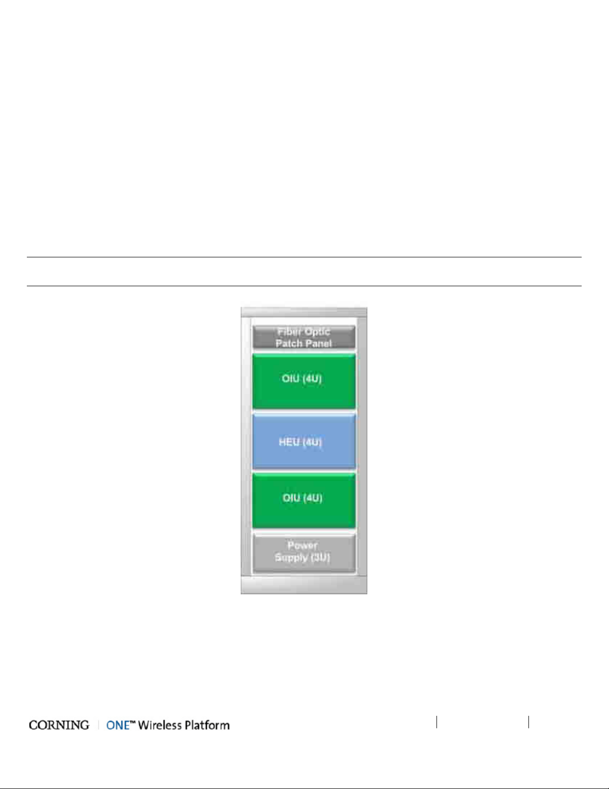
1.5.1 RF Path
At the headend, RF signals from the RF signal sources (e.g. BTS/BDA) are conditioned by service specific (conditioner) modules
in the HEU (Headend Unit) and organized into (up to three) user configurable sectors. The conditioned RF signals are converted
to optic signals by the (wideband) OIU (Optic Interface Unit) and specific sectors are routed towards selected remote locations
according to user defined configurations.
The optic fibers at the OIU are routed to the ICU (Integrated Centralized Unit) at the remote end. From the ICU the optic fibers
are distributed along with DC to the Remote Antenna Units (RAU).
Figure 1-4. RF coverage Architecture
Page 21
Introduction
P/N 709C011801
Page 21
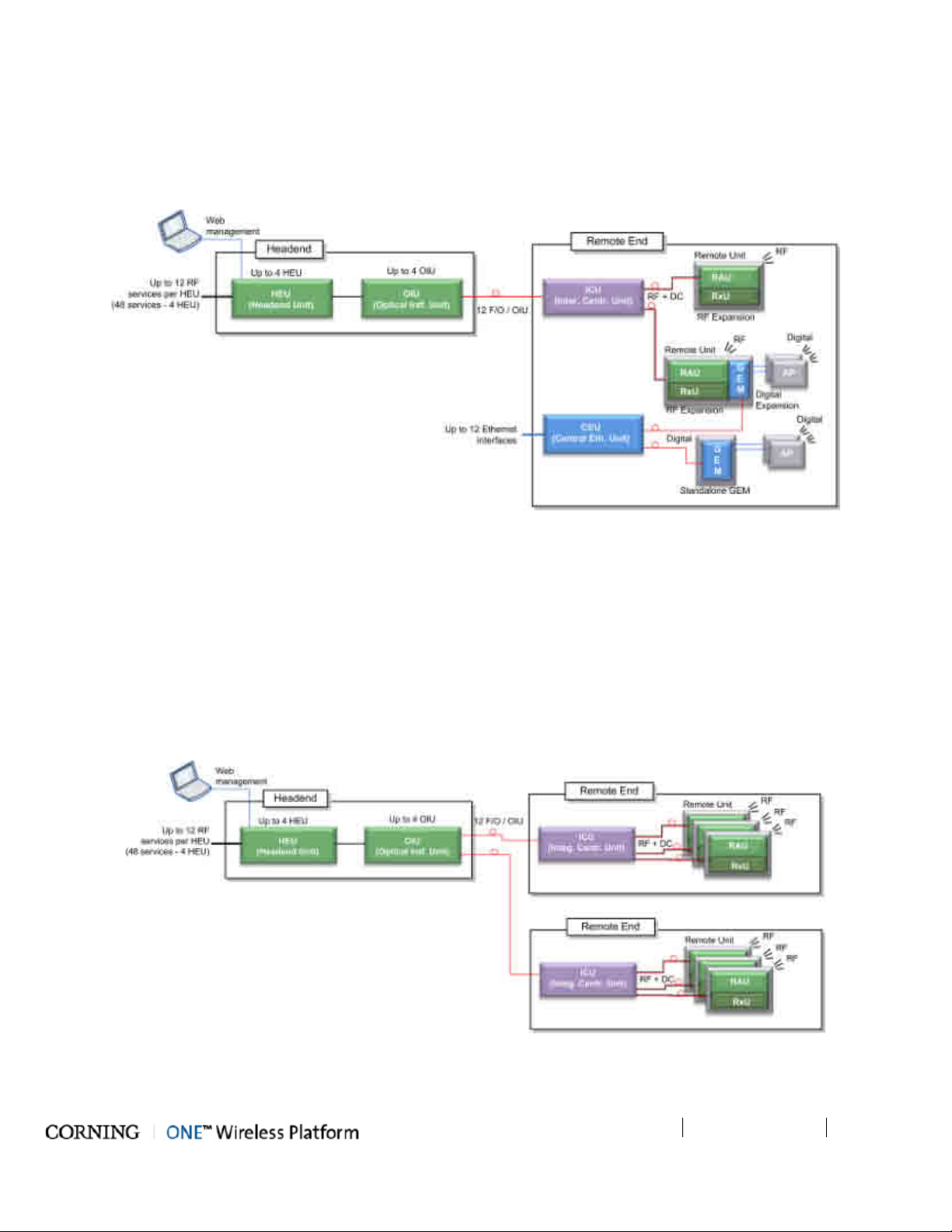
1.5.2 Digital Path
The Digital services from the corporate LAN (received via Ethernet Switch) are converted to optic signals by the CEU (Centralized
Ethernet Unit) and routed over optic fibers towards the GEM units. The optical traffic is then converted to 1GbE by the GEM
(Gigabit Ethernet Modules) modules and distributed to two third party equipment such as Access Points, Ethernet switch, etc.
NOTE: GEMs can be connected to the CEU either directly, or via an ICU (described under RF Path (on page 20)). In that case,
the ICU can also provide DC to the GEMs.
Figure 1-5. ONE™ Solution Digital Path Architecture
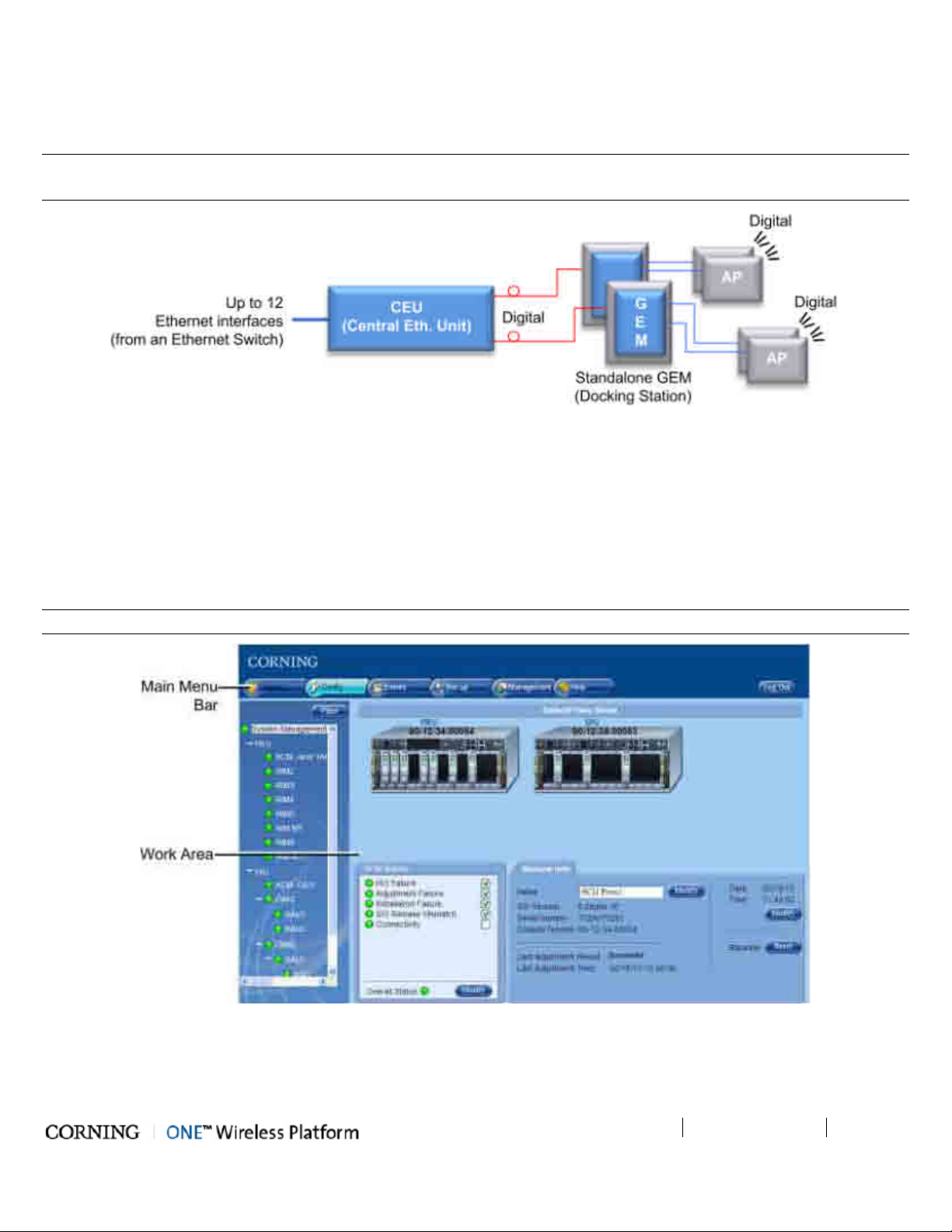
1.6 ONE™ WEB Management Application
The ONE™ solution consisting of the HEU and its hosted elements is managed via a WEB session to the HEU. The GUI based WEB
management application provides all the required configuration, management and monitoring options for the ONE™ system.
The ONE™ Web management application consists of the Main Menu bar, where the displayed side-bar and work area options
vary according to the selected menu option.
NOTE: The available tabs and capabilities vary depending on the access level used to open your session.
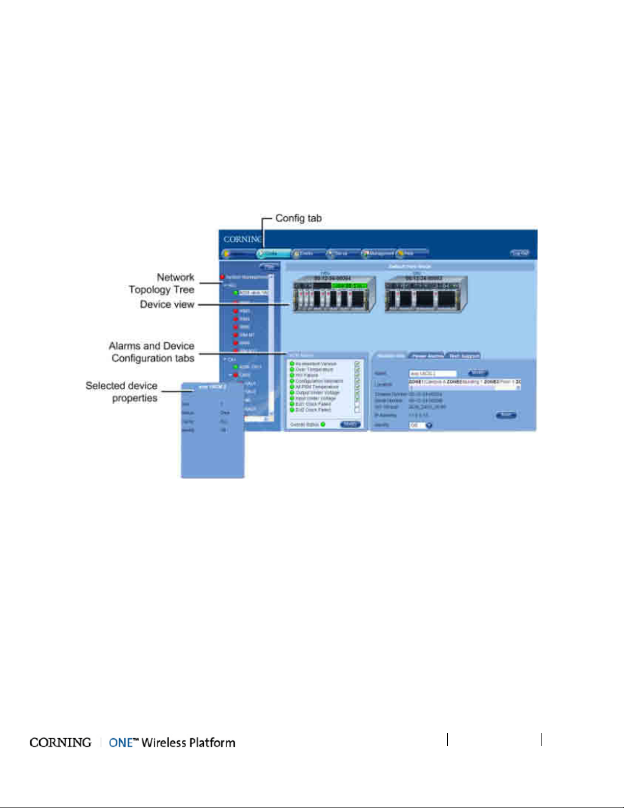
Figure 1-6. Main Window (Config Tab - Default Display)
Page 22

Introduction
P/N 709C011801
Page 22
The Main Menu Bar includes the following tabs:
on
Tab Description
Monitor N/A
Config
Displayed upon login by default. Displays general module information and
device alarms and provides the configuration options for the available
selected site devices. A brief description is given in Overall Device
Display - Config Tab (on page 22). A detailed description is given in
Device Configuration section (on page 91).
Events
Displays the events that occurred on the monitored devices and enables
generating reports. Configuration changes that are initiated by the network
manager are not considered events display. See Events Display section.
Set-up
Set-up tool used for initial system set-up, commissioning of system devices
and adjustment procedure. See About the System Setup Tool section (
page 74) for details.
Management
Provides administration options such as firmware upgrade, user management
options and IP settings required for receiving traps.
Help Provides access to Online Help
Table 1-12. Main Menu tabs
Page 23
Introduction
P/N 709C011801
Page 23
1.6.1 Overall Device Display - Configuration Tab
The Config window is displayed by default upon login and includes the following for each selected element:
• Network Topology Tree - hierarchically displays the connected and available site devices and their status.
• Device Configuration Tabs - device specific which include the configurable parameters (e.g. service control, RF parameters)
and general information (e.g. device name, Firmware version)
• Device View - visualization of device, with LEDs corresponding to the device status. Device view can be used for fault
sourcing at a glance.
• Alarms - displays the device alarms for fault sourcing and provides alarm masking options
Note the following:
• The device selected in the Network Topology Tree appears green in the Device View Mode area
• Point to module in Device View to display property info
Figure 1-7. Config Tab
1.6.2 Session Access
• Number of simultaneous sessions - the HCM supports up to three simultaneous sessions for multiple users (local/remote
access).
• Login Priorities - the login of users is enabled according to priority – when the maximum amount of multiple users are logged
in, the HEU terminates the session running for the lowest level user logged in the longest (user receives alert message and
force logout is performed) in order to enable a higher access level user to login to the system. A message indicating logon
denial appears when the maximum number of users is logged in and a lower level user attempts to log in to the system.
Page 24
Introduction
P/N 709C011801
Page 24
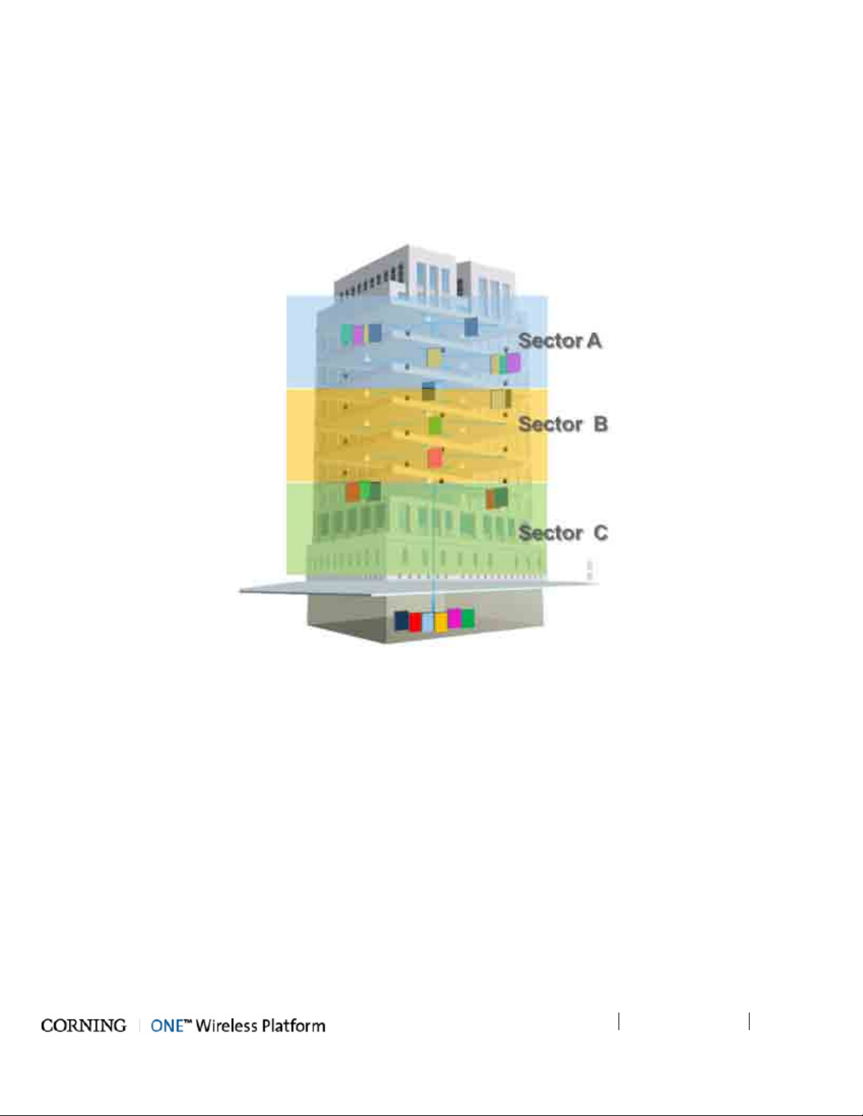
1.7 User Controlled Sectorization
ONE™ fiber-optics infrastructure allows various combinations of SISO and MIMO services to be routed from the headend to
specified remote locations on each floor, according to user defined configurations. This allows optimizing service coverage and
provides equipment savings. While the fiber-optics infrastructure is common, the services can be routed via service provider
shared or dedicated equipment. By default, the system is configured to support a single sector: all services are transferred to all
remote locations. This default configuration can be easily modified according to site requirements.
The following figure illustrates service distribution from the head-end to various locations on ach remote floor. Each color
represents a specific service, where different combinations of services are distributed at various locations on the same floor
according to coverage requirements.
Figure 1-8. Illustration of Sectorization
Page 25
Introduction
P/N 709C011801
Page 25
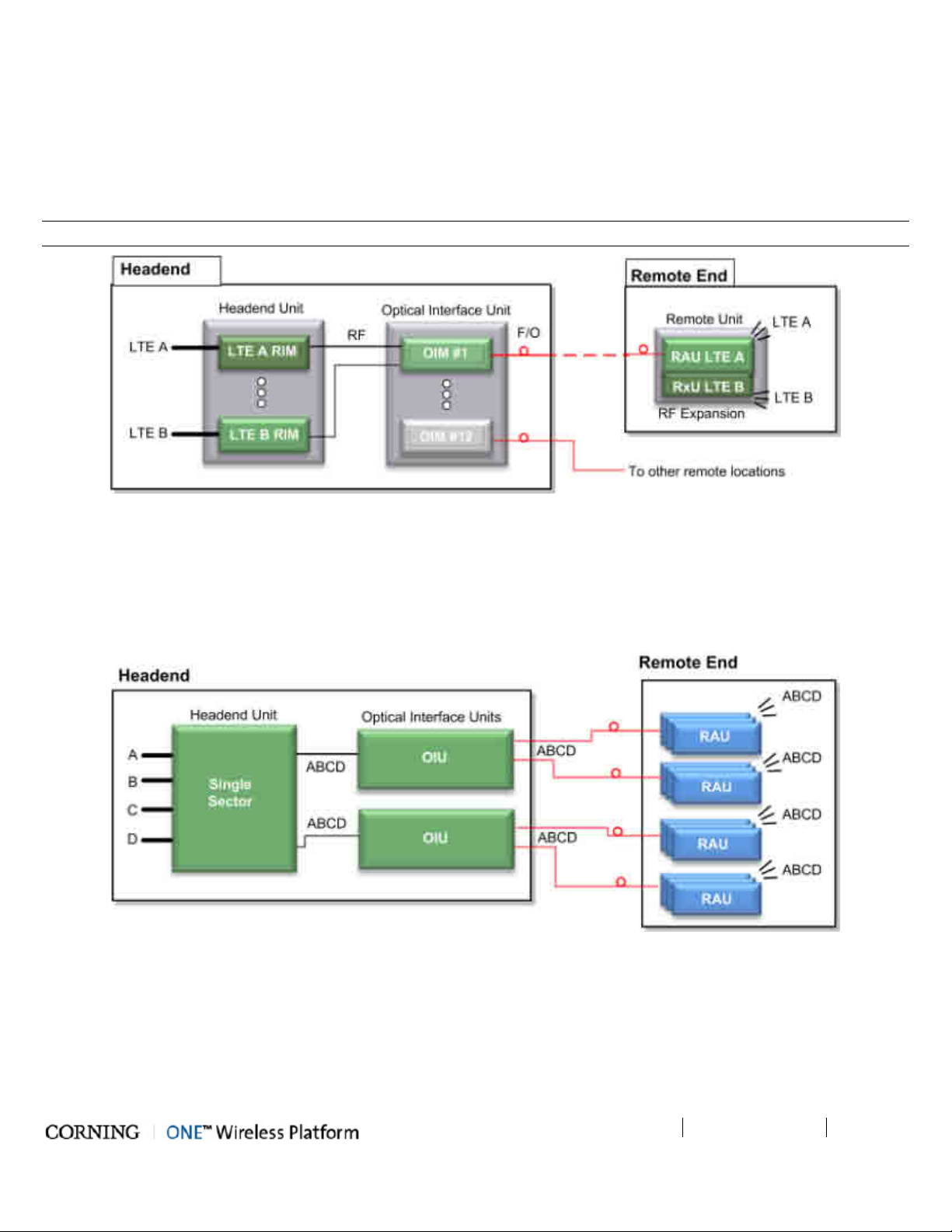
1.7.1 MIMO Configurations
MIMO topologies provide more density by using two independent RF paths for the same service, where the independent paths
are implemented by dedicated modules along the path.
MIMO configuration is implemented by routing the two RF bands over dedicated RF paths at both the entry point (in the Headend
Unit) and at the exit point (at the Remote Unit). Note that the Optical Interface Unit is wideband and the services are combined
in a single OIM for routing to the same Remote End Unit. At the Remote End Unit, the services are distributed by two dedicated
modules.
NOTE: MIMO configuration can also be implemented by two separate Remote End Units.
Figure 1-9. Example of MIMO Configuration
1.7.2 Single Sector Example
In this example, all four services (A,B,C,D) are routed to all (up to 72) remote locations. In the illustrated topology, a single HEU
conditions the services and feeds them to two OIU systems for conversion to optic signals. Each OIU supports up to 36 RAU
(Remote Antenna Units).
Figure 1-10. Single Sector Configuration
Page 26
Introduction
P/N 709C011801
Page 26
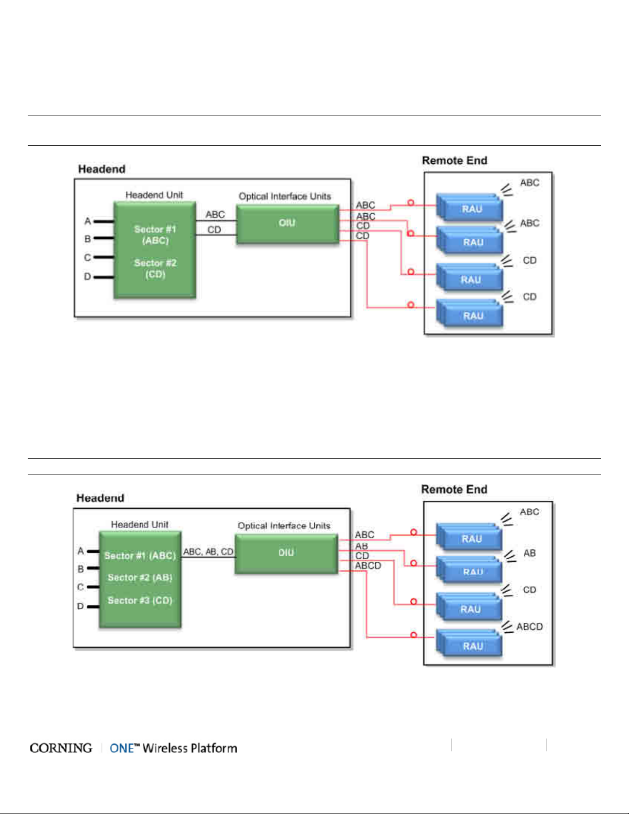
1.7.3 Dual Sector Example
In this example, two sectors (groups/layers) of services are defined: A,B,C and C,D. Note that a service can be allocated to any
of the sectors at the same time. For example, service C is allocated to both Sectors. Both sectors are routed to the OIU for optic
conversion. Each OIU module (OIM) can be configured to support either one or (if they do not have a common band) to both
sectors and the corresponding services are routed from the OIM to its hosted RAU units.
NOTE: In the example below, band C is common to both Sector #1 and #2; therefore, an OIM cannot be assigned both sectors
(i.e. ABC + CD).
Figure 1-11. Example of Dual Sector Configuration
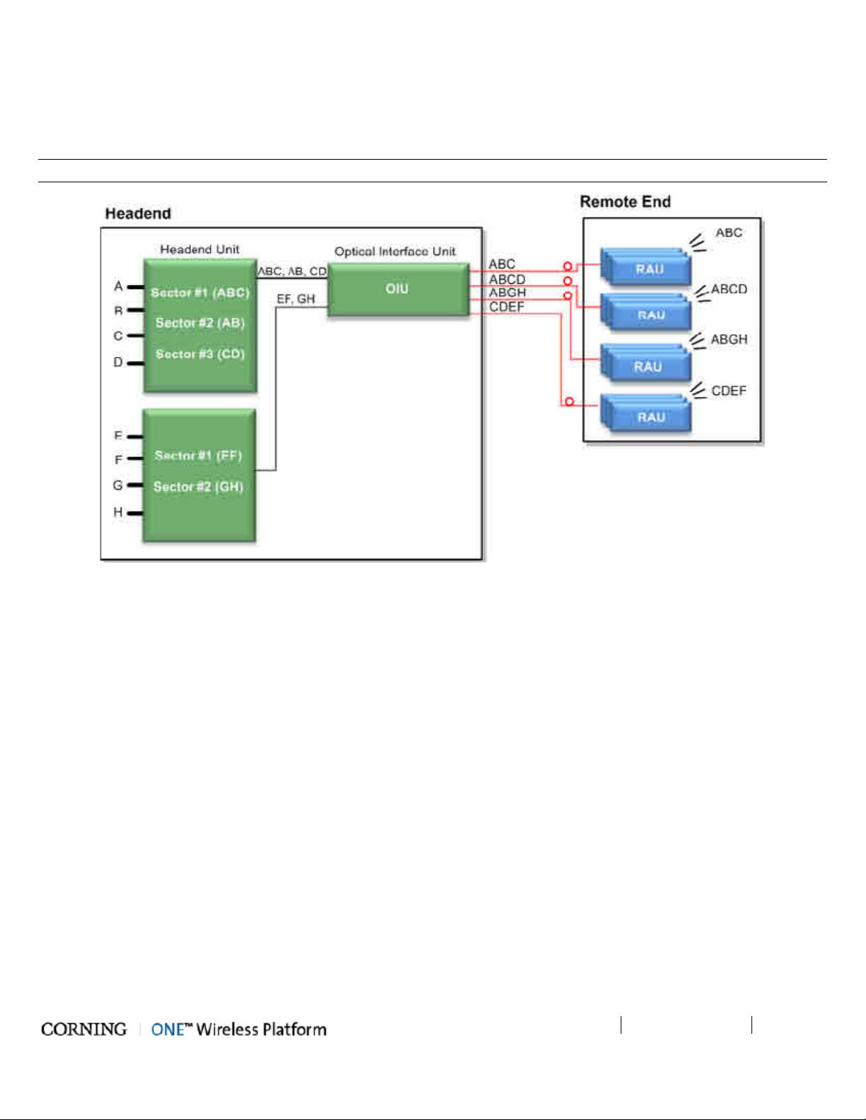
1.7.4 Tri-sector Example
In this example, three sectors (groups/layers) of services are defined: ABC, AB,CD. Note that a service can be allocated to any
of the sectors at the same time. For example, services C and B are allocated to two of the sectors. The sectors are routed to
the OIU for optic conversion. Each OIU module (OIM) can be configured to support either one, two or three sectors in any
combination and the corresponding services are routed from the OIM to its hosted RAU units.
NOTE: An OIM cannot support two sectors that have a common band (e.g. ABC and BC, or ABC and CD).
Figure 1-12. Example of Tri-sector Configuration
Page 27
Introduction
P/N 709C011801
Page 27
1.7.5 Tri-sector Example with Two HEUs
This tri-sector example supports two HEUs. In this topology, one HEU supports three sectors (groups/layers) and the other two
sectors for a total of five sectors. These groups of services are all routed towards a common OIU. Each OIU module (OIM) can
be configured to support any (legal) combination of sectors and the corresponding services are routed from the OIM to its hosted
RAU units.
NOTE: Multiple sectors allocated to the same OIM cannot share any identical frequency bands.
Figure 1-13. Example of Tri-sector Configuration with Two HEUs
Page 28

Page 29
Unit Descriptions - RF Path
P/N 709C011801
Page 29
2 Unit Des criptions - R F P ath
This chapter provides detailed descriptions of the ONE™ solution components. The descriptions are organized according to RF
and Digital path headend and remote end components. This includes port and LED interface descriptions.
2.1 RF Path - Headend Components
ONE™ RF Path coverage solution includes the following headend elements:
• HEU – Headend Unit
• OIU – Optical Interface Unit
Figure 2-1. RF Path Headend Components
2.1.1 HEU (Headend Unit)
The HEU performs the following main functions:
• Conditions (up to 12) RF sources to a level required for feeding to the Optical Interface Unit (OIM).
• Enables the configuration of up to three sectors consisting of groups of RF services.
• Provides single source control and management of the ONE™ solution RF path.
Each HEU supports up to 12 services. For additional services or density, two or more HEU units can be cascaded in a
Master/Slave configuration that is managed from the Master HEU. For HEU installation procedure, see section Installation –
RF Path Elements (on page 45).
Page 30
Unit Descriptions - RF Path
P/N 709C011801
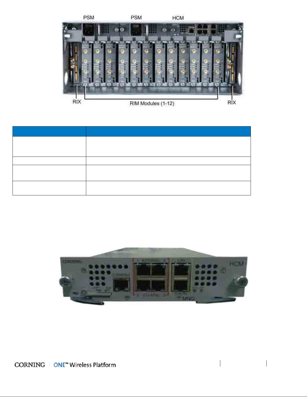
Page 30
Figure 2-2. HEU Front Panel with Installed Modules
Module Description
HCM (Headend Control
Module) (on page 30)
Provides system management and control functions. In Master/Slave
configurations, HCM is installed in the Master and ACM (on page 34) in
the Slave.
PSM (Power Supply Modules) 110-230VAC. If two are installed, both must be powered on.
RIX (RF Expander Module) – Service specific conditioner units.
OIX (Expander Module (on
page 32))
Used to interface with the parallel Expander Unit on the HEU.
Table 2-1. OIU Front Panel Interface Definitions
2.1.1.1 HCM (Headend Control Module)
The HCM provides management and control capabilities for the ONE™ system. Each INTERNAL port is dedicated to a single OIU
(see OIU (on page 33)) management connection. The HCM module includes Local and LAN management ports and LED status
indicators.
Figure 2-3. HCM Module
Page 31

Unit Descriptions - RF Path
P/N 709C011801
Page 31
used for management of connected OIU systems
Port Description
INTERNAL (TO ACM)
[4] RJ45, 100Mb Ethernet ports (and/or HEU Slaves).
LAN RJ45, 1Gb Ethernet port - connects to the corporate LAN for remote management
LOCAL RJ45, 1Gb Ethernet port - local configuration and management
CONSOLE RJ45, serial port - local configuration for service personnel
SD Card Slot Supports uSD cards up to 32GB (used for example for saving configuration files)
Table 2-2. HCM Ports
LED Description
PWR
Steady Green - Power supplied to unit
Off – No power is supplied to the unit
Steady Green – HCM Boot up sequence complete and functioning
RUN
Blinking Green – HCM Boot up sequence in process
Off – No power supplied to the unit
SYS Indicates overall status of the managed system
FAN
Green – Normal operation status
Red – Faulty fan (s)
Table 2-3. LED Description
2.1.1.2 RIM/RIM-M (RF Interface Module)
Up to 12 service specific conditioning modules are installed in the HEU chassis. Each RIM supports both Simplex and Duplex RF
connectors. RIM-M modules support MIMO services (e.g.700 MHz LTE, AWS). LEDs provide status indications on signal level and
module operation.
Figure 2-4. RIM Module
Page 32

Unit Descriptions - RF Path
P/N 709C011801
Page 32
The following tables provide a description of the RIM ports and LED status indicators.
Port Description
DL/UL UL and DL simplex connections to the RF signal source
DUP Duplexed UL and DL connection to the RF signal source
Table 2-4. RIM Ports Description
LED Description
Green – RF signal is at normal level
Protect
Red (Blinking) - Indicates the RF signal is too high and that the protection
mechanism is enabled
DL High
DL Low
Provides indication on DL RF level in conditioner module:
Red – Signal is 2 dB above max. expected power
Provides indication on DL RF level in conditioner module::
Red – No signal or 15 dB below max. expected power
Steady Green - Power on and module SW has initialized and is up and
running
RUN
Blinking Green- Fault detected (e.g. RIM module SW halted) orSW
upgrade in process
Off - No power
PWR On - Input power is within required range
Table 2-5. RIM LED Descriptions
Page 33

Unit Descriptions - RF Path
P/N 709C011801
Page 33
2.1.1.3 RIX (RF Expander Module)
The RIX Expander module provides the RF interface to the OIU unit. Two RIX Expander modules can be installed in each HEU
chassis, to support up to four OIU (per HEU). If only one Expander module is installed, it is required to terminate the empty slot
with the supplied termination.
NOTE: The OIU Expander Modules are similar in appearance to the HEU Expander modules but are NOT INTERCHANGEABLE.
Each Expander module is indicated as RIX or OIX on the bottom of the module.
Figure 2-5. RIX Expander Module Interfaces
2.1.1.4 PSM (Power Supply Module)
NOTE: The Power Supply modules and installation are the same for the HEU and OIU chassis. If two power supplies are
installed, both must be switched ON to begin system operation.
The HEU (and OIU) chassis can support two power supply modules (110-240VAC), where the second power supply provides
redundancy in case one of the supplies fails. If two modules are installed, both must be connected to the AC outlet and turned
on at all times.
Figure 2-6. Power Supply Module
Page 34

Unit Descriptions - RF Path
P/N 709C011801
Page 34
2.1.2 OIU (Optical Interface Unit)
The OIU interfaces to the HEU, performs the RF to optic conversion of the received signal and distributes the wireless RF services
to the RAU units over the fiber optic infrastructure to the remote site. Each OIU supports up to 12 SM optic fibers (one fiber per
OIM), which are routed to up to 36 RAU (three Remote Antenna Units per OIM).
Figure 2-7. OIU Front Panel with Installed Modules
Module Description
ACM (Auxiliary Control
Module) (on page 34).
Auxiliary Control Module – interfaces with the HEU's HCM to provide
remote management capabilities.
PSM (Power Supply Modules) 110-230VAC. If two are installed, both must be powered on.
OIM (Optical Interface
Module) (on page 35)
OIX (Expander Module (on
page 32))
Wideband, optical to RF (and vice versa) conversion units.
Used to interface with the parallel Expander Unit on the HEU.
Table 2-6. OIU Front Panel Interface Definitions
Page 35

Unit Descriptions - RF Path
P/N 709C011801
Page 35
2.1.2.1 ACM (Auxiliary Control Module)
The ACM provides basic control functions (only) for the host chassis via a local connection. The ACM module can be remotely
managed via an HCM (on page 30) connection.
Figure 2-8. ACM Module
Port Description
INTERNAL
(TO HCM)
[4] RJ45, 100Mb Ethernet ports used for OIU and/or HEU slave management connections
Console [1] RJ45, serial port used for basic IP configuration and local connection for service personnel
Table 2-7. ACM Ports Description
LED Description
PWR
Steady Green - Power supplied to unit
Off – No power is supplied to the unit
Steady Green – HCM Boot up sequence complete and functioning
RUN
Blinking Green – HCM Boot up sequence in process
Off – No power supplied to the unit
SYS Indicates overall status of the managed system
FAN
Green – Normal operation status
Red – Faulty fan (s)
Table 2-8. ACM LED Indicators Description
Page 36

Unit Descriptions - RF Path
P/N 709C011801
Page 36
2.1.2.2 OIM (Optical Interface Module)
The OIM is a wideband RF to F/O (and vice-versa) media conversion module. Up to 12 OIM units can be installed in each OIU,
where each OIM can support up to three Remote Antenna Unit (RAU) connections.
Figure 2-9. Optical Interface Module
Port
Description
Optical Link MTP Connector for optical interface connection; SMF
Expansion
[6] Kenpole connector for 1:1 direct signal transportation, 3 UL and 3 for DL
Enables (DL and UL) broad band connection to each optical link
Table 2-9. OIM Ports Description
LED Description
ON - the optical link to/from the connected remote functions within the
Link 1-3
specifications in both directions.
Blinking - optical power from remote is lower than required
RUN Steady Green – SW Boot up sequence complete and functioning
PWR Steady Green – Power input detected for corresponding module
Table 2-10. OIM LED Descriptions
Page 37

Unit Descriptions - RF Path
P/N 709C011801
Page 37
2.1.2.3 OIX (Optical Expander Module)
Each OIX Expander module provides the RF interface to up to two HEU units via two 9-pin connectors. Two OIX Expander
modules can be installed in each OIU chassis. Up to four OIU units can be hosted by an HEU. If only one Expander module is
installed, it is required to terminate the empty slot with the supplied termination.
NOTE: The OIU Expander Modules are similar in appearance to the HEU Expander modules but are NOT INTERCHANGEABLE.
Each Expander module is indicated as RIX or OIX on the bottom of the module.
Figure 2-10. OIX Expander Module Interfaces
Page 38

Unit Descriptions - RF Path
P/N 709C011801
Page 38
2.2 RF Path Remote End Site Components
The RF coverage solution remote end components comprise the following elements:
• ICU (Intermediate Centralized Unit) - forwards optics along with DC to the RAU and its sub-modules.
• RAU (Remote Antenna Unit) - provides RF distribution and includes internal antennas. It can also encase data distribution
module (GEM).
• RxU (Remote Expansion Unit) - installed in the RAU. Provides support for two additonal RF services for a total of 6 services
per RAU.
Figure 2-11. RF Path Remote End Components
A detailed description of the remote end components is provided in the following sections
2.2.1 ICU (Intermediate Centralized Unit)
NOTE: The ICU can also be used on the digital path.
The ICU is installed at the floor level. It provides the LC/APC optical interface along with DC power to the RAU RF (and data)
sub-modules. The optical and DC signals are routed via a composite cable connected between the ICU and hosted RAU modules.
The optics signal is provided via one or two dedicated Edge modules that convert MTP optic interfaces to LC/APC interface; the
DC power is provided by up to four dedicated power supplies. A single power connection feeds all ICU power supply modules.
Figure 2-12. ICU Front Panel Interfaces and Modules
Page 39

Unit Descriptions - RF Path
P/N 709C011801
Page 39
Interface Description
Power Connectors
LC/APC
Up to eight DC power connectors, depending on number of power supply
modules installed.
SM optics connectors implemented by up to two Edge modules inserted
from the rear: six connectors per Edge module.
AC Power Input 110-230VAC power input to unit.
Table 2-11. ICU Front Panel Interface Descriptions
Edge modules and power supplies are extracted and inserted from the rear of the unit.
Figure 2-13. ICU Rear Panel Interfaces and PSM Modules
2.2.2 RAU (Remote Antenna Unit)
The RAU distributes up to four RF services via internal antennas (external antennas are optional). The RF services are received
over optic cables and converted for distribution over internal (or optionally external) antennas.
Figure 2-14. RAU Module
NOTE: The RAU enclosure can host two additional modules: RxU for MIMO support and GEM for digital coverage. See relevant
sections for details on these modules.
Page 40

Unit Descriptions - Digital Path
P/N 709C011801
Page 40
Interface Description
in case of PoE clients. Used when GEM modules are installed
MGMT RJ45 local management connection
DC power inputs
PWR
Main - connect to DC (from composite cable)
Secondary –
(in addition to Main)
F/O LC/APC SM connectors for UL and DL optic connections
Listening Mode N/A
RF Filter (e.g. LTE, CELL)
External Antenna
QMA RF ports for external cavity filter use (In/Out). For CELL and LTE
filters.
Optional connection to broadband external antennas. Requires GUI
configuration (internal antenna is enabled by default).
Table 2-12. RAU Interfaces
2.2.2.1 RxU (Remote Expansion Unit)
The RxU is an Add-on to the RAU which provides support for MIMO services (i.e. 700MHz LTE, AWS).
Figure 2-15. RxU Interfaces
Module Description
Filter Filter connections to the corresponding filter.
RF Connection to external antenna, used for above-ceiling installation.
External Antenna
(Both the RxU and the RAU antennas are used since this implements a MIMO
configuration)
External RF Filters QMA RF ports for external cavity filter use. For CELL and LTE filters.
RUN LED Indicates SW is up and running.
Table 2-13. RxU Front Panel Interface Connections
Page 41

Unit Descriptions - Digital Path
P/N 709C011801
Page 41
3 Unit Des criptions - Digital Path
This chapter provides detailed descriptions of the Digital Path components.
3.1 Digital Path Components
The digital path comprises the following elements - located at the remote end
• CEU – Centralized Ethernet Unit
• GEM – Gigabit Ethernet Module -
NOTE: The GEM module can be installed in two configurations: in the RAU enclosure or (as illustrated below) as a standalone
unit in a Docking Station.
Figure 3-1. ONE™ Digital Path Architecture
3.2 CEU (Centralized Ethernet Unit)
The CEU is a Centralized Ethernet-over-Fiber Media Converter Unit. Located at the remote end, it converts Ethernet media (from
a LAN switch) to fiber media for routing towards GEM modules. The CEU hosts three Centralized Media Converter Modules
[CEMs]. Each module supports four Ethernet ports (LAN switch connections) and four F/O connectors (towards GEM modules).
Figure 3-2. CEU Front Panel with Installed CEM Module
Figure 3-3. CEU Rear Panel
Page 42

Unit Descriptions - Digital Path
P/N 709C011801
Page 42
3.2.1 CEM (Centralized Ethernet Module)
The CEU supports up to three CEM modules, where each CEM supports four Ethernet ports (LAN switch connections) and four
F/O connectors (towards GEM modules). All interfaces (except for power) are located on the front panel (see section CEM).
Figure 3-4. CEM Interfaces (Installed in CEU)
The CEM module interfaces include Ethernet connections to the Ethernet switch, F/O connections and LED status indicators.
The following table provides a description of the CEM ports.
Port Description
ETH Four ETH connections to LAN switch
F/O
USB port
[4] 10/100/1000BASE-T RJ-45 connectors to [4] LC/UPC fiber connectors (using SFP
–small-form pluggable module)
USB serial port - service port
PWR Steady Green – Power input detected for corresponding module
Table 3-1. Ports Description
Page 43

Unit Descriptions - Digital Path
P/N 709C011801
Page 43
3.3 GEM (Gigabit Ethernet Module)
The GEM converts the received optical signal to two Ethernet digital connections, which are then routed along with PoE to two
remote access points. The GEM module can be installed in the following configurations:
• Installed in RAU - as an optional plug-in module (see RAU (on page 39))
• As a standalone module (GEU-S) - (see section GEU-S Installations (on page 52))
Figure 3-5. GEM Interfaces
The following tables provide descriptions of the ports and LED indicators.
Port Description
PORT A/PORT B
FC/APC [1] LC/UPC Fiber optic port
Table 3-2. GEM Port Interfaces
LED Description
PoE (PORT A/PORT B) Indicates power supplied to connected AP
Link
RUN Steady Green – GEM module SW is up and running
Table 3-3. GEM LED Indicator Descriptions
[2] RJ45 ports supporting 10/100/1000Base-T copper interface with
PoE+ 802.3at PSE capability for connections to remote access points
ON - the optical link to/from the connected remote functions within the
specifications in both directions.
Blinking - optical power from remote is lower than required
Page 44

Unit Descriptions - Digital Path
P/N 709C011801
Page 44
3.4 GEU-S (GEM Standalone)
The GEU-S serves as the GEM docking station, enabling it to function as a standalone unit. The GEU provides the mounting
option and DC power supply for the GEM module. See GEU-S Installations (on page 52) section for details on installation.
Figure 3-6. GEU Enclosure: Top (Left) and Open Underside (Right)
Page 45

Installation – RF Path Elements
P/N 709C011801
Page 45
4 Ins tallation – R F Path E lements
This chapter describes the installation of the RF path components. It contains only brief descriptions of the approach of each
installation procedure. For step-by-step installation descriptions, refer to the Quick Start Guides provided with the ordered units
and modules, and for specific guidelines on infrastructure planning, design and installation, please consult with a Corning
Product Line Manager or Corning approved Installer.
4.1 RF Headend Installation
The (RF coverage) headend site installation consists of installing the HEU and OIU units.
Note the following information (for both HEU and OIU units):
• The chassis and modules are supplied separately and must be inserted by the user. Only the fan module is factory installed
in the HEU/OIU chassis rear.
• The HEU and OIU units are installed at the IDF (Intermediate Distribution Frame), adjacent (or as close as possible) to each
other to facilitate the connections.
• Hot-swappable modules: RIM (RF Interface Modules) and Power Supply(ies), Fan Modules and RIX/OIX (HEU/OIU
Expander Modules). HCM, ACM modules are not hot-swappable.
• If a redundant power supply is provided, both supplies must be installed, connected to AC power and switched ON.
4.1.1 HEU Installation
Note the following information:
• The RF service interfaces are implemented by service specific RIM/RIM-M modules that are provided separately according to
your order.
• In a Master/Slave configuration, the HEU unit determined as the Slave is managed via the Master unit using an RJ45
connection. Also, the Slave HEU will include an ACM (Auxiliary Control Module) and not an HCM.
Page 46

Installation – RF Path Elements
P/N 709C011801
Page 46
To install HEU
1. Mount HEU chassis - mount the (empty) HEU chassis in the 19-in rack.
2. Install modules - install modules (RIM, RIX, PSM and HCM (or ACM for Slaves) into their respective slots (see following
figure).
IMPORTANT! Unoccupied RIX (Expander Module) slots must be terminated with an Expander Termination module.
Figure 4-1. Fully Occupied HEU Chassis
3. Power-On - connect the power cable(s) to the AC outlet(s) and switch On. If two PS modules are installed, both must be
connected.
4. RF connections - connect the RIM/RIM-M QMA (simplex or duplex connections) to the corresponding RF source (e.g.
BTS, BDA).
IMPORTANT! Be sure to terminate any unused QMA connectors with 50 ohm terminators.
5. HEU Management connections:
• Master/Stand-alone HEU - connect HCM LAN port to the corporate LAN
• Slave HEU - connect a Slave ACM RJ45 INTERNAL port (any port) to a Master HCM RJ45 INTERNAL port.
6. HEU to OIU connections:
• RF - connect the HEU RIX to the corresponding OIU OIX port using the expander cable (provided with the OIU).
• Management - connect an HEU HCM/ACM INTERNAL port to an OIU ACM INTERNAL port.
7. Verify HEU normal operation:
• Check LEDs on the HCM/ACM. See section HCM (Headend Control Module) (on page 30)
• Check LEDs on each RIM/RIM-M module. See RIM (RF Interface Module) (on page 31).
Page 47

Installation – RF Path Elements
P/N 709C011801
Page 47
4.1.2 Example of HEU Master-Slave Installation
A Master-Slave HEU configuration enables single source management of several HEUs (and hosted elements) from a single HCM.
The following figure provides an example of the connections between a Master and one Slave.
Each OIU is connected to its host HEU through two connections: MGMT (ETH to INTERNAL port) and RF (RIX/OIX ports). For
standalone configurations, up to four OIU can be connected to an HEU; for Master/Slave configurations, up to three OIU can be
connected to an HEU (since one of the MGMT ports is used by the Master/Slave connections.)
Figure 4-2. Example of Connections for Master-Slave Configurations
4.1.3 OIU Installation
Note that each OIU interfaces to one HEU; each OIM interfaces to up to three RAU units (located at the remote end) via an MTP
connection.
To install OIU
1. Mount OIU - mount the (empty) OIU chassis in the 19-in rack.
2. Install modules - install modules (OIM, OIX, PSM and ACM) into their respective slots. See following figure.
IMPORTANT! Unoccupied OIX (Expander Module) slots must be terminated with an Expander Termination module.
Figure 4-3. Fully Occupied OIU Chassis
3. Power-On - connect the Power Supply Module(s) to the AC outlet(s) and switch On. If two modules are installed, both
must be connected.
4. HEU connections:
o Connect the OIU OIX to the corresponding HEU RIX port using the provided Expander cable.
o Connect an ACM INTERNAL port to an HEU HCM INTERNAL port with an Ethernet cable.
5. OIM connections - connect the optic modules to the designated optic ports in the fiber-optic patch panel.
6. Verify OIU normal operation - via the LED indicators on the ACM and OIM modules. See sections ACM (Auxiliary
Control Module) (on page 34) and OIM (Optical Interface Module) (on page 35) respectively for description of
LEDs.
Page 48

Installation – RF Path Elements
P/N 709C011801
Page 48
4.2 RF Remote-End Installation
The remote end site (RF coverage) installation consists of installing the ICU (on page 48) unit and RAU (on page 48) module(s).
4.2.1 ICU Installation
4.2.1.1 General Information
• The ICU is a passive unit installed at the floor level and provides the power and fiber interfaces to the RAU units (and to the
GEU for the digital path).
• Connections between the ICU and the RAU units are performed via Corning composite cables (ordered separately) consisting
of:
• 2 DC wires
• 3 LC/APC pairs
• The chassis and modules are supplied separately and must be inserted by the user.
• All ICU modules (i.e. PS and Edge) are hot-swappable
• Each ICU chassis hosts up to four Power Supply modules and up to two Edge modules
To install the ICU
1. Install modules - install Power Supply (from rear) and Edge modules (from rear/front).
Figure 4-4. Location of Modules in ICU
2. Mount ICU - mount the ICU in a 19-in rack or on wall.
3. OIU connections - connect the optic fibers from the patch panel on the floor level leading from the OIU to Edge module
MTP connector (accessed from ICU rear).
4. RAU connections – using the Corning composite cable, connect the DC wiring and LC/APC fibers to the corresponding
ICU Edge module and DC power connectors and to the relevant RAU(s).
5. Power up – connect the ICU to the AC power outlet using the provided 110-240V AC power cable.
Page 49

Installation – RF Path Elements
P/N 709C011801
Page 49
4.2.2 RAU Installation
4.2.2.1 General Information
• The RAU modules are deployed on the floor level and interface to the RF antennas.
• The RAU can be provided in a number of configurations:
• RAU (without RxU and GEM)
• RAU + RxU
• RAU + GEM
• RAU + RxU + GEM
NOTE: Existing RAU units can be upgraded with RxU and/or GEM modules – relevant Quick Start Guide with installation
instructions are provided with ordered units.
• The RAU supports various mounting installation options: wall/ceiling/acoustic ceiling
If the RAU is installed below or mid-mount an acoustic ceiling, a support bar (T-Bar) is required (not included).
Acoustical Ceiling grid work is not designed to support the weight of the enclosure.
• RAU optic fiber connections and DC power are provided via a Corning Composite cable (ordered separately).
To install the RAU
1. Locate fiber and DC connections cables - Corning Composite cable wiring leading from ICU.
NOTE: RAU units that include GEM modules, require additional DC wire for Secondary Power connection and Ethernet.
2. Mount the installation bracket according to one of the following installation options:
• Wall-mount: mount bracket on wall
• Concrete/Above Acoustic Ceiling: route connections cables through bracket and install bracket on ceiling
NOTE: When installing above acoustic ceiling, allow for at least 22 mm (0.86 in) above the acoustic ceiling for ventilation.
Figure 4-5. RAU Installed Above Acoustic Ceiling
3. Below/Mid-Mount Acoustic ceiling: Cut-out opening in acoustic tile (mid-mount only), install T-Bar in ceiling above, route
connections and install bracket on T-Bar.
NOTE: For Below ceiling installations - 22 mm (0.86 in) between ceiling tile and RAU; For Mid-Mount installations - 63.5 mm
(2.5 in) between ceiling and lowest part of RAU.
Figure 4-6. Below Ceiling Installation (left figure) and Mid-Mount Ceiling Installation (right image)
4. Connect cables:
Page 50

Installation – RF Path Elements
P/N 709C011801
Page 50
• DC connection:
o RAU (without GEM) - MAIN POWER connection
o RAU + GEM - MAIN POWER + SECONDARY POWER connections
• Fiber optic connection
• External antenna (for above ceiling installations)
• (Optional) RF filter connections (check with site planner) - for RAU and RxU (if exists)
• GEM module connections (for RAU+GEM) - Ethernet and 3PE connections
5. Verify normal operation - via front cover LEDs:
• RUN - Blinking green
• LINK – Steady green
• POWER – Steady green
4.2.3 RxU Installation
4.2.3.1 General Information
• The RxU expands the RAU band support to additional 2 MIMO bands.
• The RxU can either be pre-installed in the RAU module (according to order) or easily added at a later stage when required.
• The installation of the RxU module in the RAU unit does not require disconnecting cables or power.
To assemble RxU on to RAU
1. Dismount RAU from mounting bracket and remove RAU enclosure cover.
2. Assemble RxU - fit RxU into dedicated location (on the right) and replace cover (except for front panel).
Figure 4-7. RAU and RxU Module Assembly
3. (If required by site planner) - connect the filter to the RF filter connectors on the RxU.
4. Verify normal operation – via front enclosure cover:
• RUN – Blinking Green
• POWER – Steady Green
• LINK – Steady Green
5. Re-mount RAU onto mounting bracket.
Page 51

5 Ins tallation – Digital Coverage E lements
This chapter describes the installation of the Digital Coverage components. It contains only brief descriptions of the approach of
each installation procedure. For step-by-step installation descriptions refer to the Quick Start Guides provided with the ordered
units, and for specific guidelines on infrastructure planning, design and installation, please consult with a Corning Product Line
Manager or Corning approved Installer. All these elements are installed at the remote end.
5.1 CEU Installation
General Information
• The CEU interfaces to the main Ethernet switch and to the remote Gigabit Ethernet Modules (GEM).
• The CEU is rack mounted or wall mounted at the IDF (Intermediate Distribution Frame).
• The CEU can host up to 3 CEM (Centralized Ethernet Modules), which are not included in the CEU package.
• The CEM Tx/Rx Ethernet fiber ports, used for interfacing to the GEM modules, require SFP modules (included) and LC-UPC
to LC-APC adapter.
To install the CEU
1. Install CEM modules in the CEU chassis.
2. Mount CEU chassis - rack mount or wall mount
3. Connect CEM to main LAN (Ethernet switch).
4. Con
5. nect fiber – fiber connections between CEU SFP modules and GEM modules.
Figure 5-1. CEU Ethernet and Fiber Ports
6. Power up – using 110-240VAC power cable.
7. Verify normal operation - via F/O, ETH and PWR status LEDs.
Installation – Digital Coverage
Elements
P/N 709C011801 Page 51
Page 52

Installation – Digital Coverage Elements
P/N 709C011801
Page 52
5.2 GEM
The GEM unit is either pre-installed in the RAU unit or in the Gigabit Ethernet Unit (GEU):
• RAU + GEM configurations - only require GEM module connections to Ethernet and 3rd party Access Points (DC power
provided via RAU Secondary Power connection)
• GEU (includes GEM) configurations - standalone installation which requires mounting the GEU and performing the power and
Ethernet connections.
NOTE: GEM modules can also be installed in existing RAU enclosures for expanded data coverage. Detailed instructions on how
to install the GEM module in an RAU enclosure are provided in the Quick Start Guide provided with the module.
5.2.1 GEM Installations with RAU Module
To mount the GEM on to the RAU module
1. Dismount the RAU (if already installed).
2. Plug in the GEM module into the dedicated location (left side of the RAU module) and replace cover (except for front
panel).
Figure 5-2. Inserting GEM in the RAU Enclosure
3. Remount the RAU.
NOTE: Refer to GEM QSG for a more detailed procedure.
Page 53

Installation – Digital Coverage Elements
P/N 709C011801
Page 53
5.2.2 GEU-S Installations
To install the GEU-S assembly
1. Locate the Ethernet and DC power wiring cables.
2. Hold the GEU near the mounting mechanism (not provided) and route the ETH and F/O cables through the mounting
bracket. See QSG for details.
3. Mount the GEM with GEU enclosure onto a mounting mechanism.
Figure 5-3. Overview of GEU-S Installation
Page 54

Page 55

Commissioning the System
P/N 709C011801
Page 55
6 Commissioning the S ystem
After physically installing all of the headend and remote-end elements, the initial setup procedure can be performed and the
system can be commissioned either via a local or remote connection.
NOTE: When unconfigured elements are detected the following message appears in the Config window of the Web Management
GUI: "New uncommissioned units found, please run setup".
The initial setup procedure consists of the following steps:
• Opening a local Web Management session (on page 55) using the default IP address assigned to the HEU
• Configuring the LAN and LOCAL Port Network Settings (on page 56) for remote or local management
• Performing required pre-setup procedures
• Running the Setup procedure (on page 62)
• Performing the System Adjustment Procedure (on page 73)
6.1 Opening a Local Session
To open a local Web Management session
1. Verify that your computer Local Area Connection (Properties / TCP/IP / Properties) is set to obtain the "DNS Server Address
Automatically".
2. Connect a computer (i.e. laptop) directly to the HEU HCM LOCAL port via the supplied RJ-45 Ethernet cable (P/N
705900003) as shown in the following figure.
WARNING! DO NOT connect the HCM LOCAL port to a network as its DHCP server can disrupt LAN IP addressing.
Figure 6-1. Local Connection Between (HEU) HCM and Computer
3. Assign your computer an IP address to operate in the same subnet as the HCM (default HCM IP address = 193.168.1.1).
4. Open the Web browser and enter the HCM IP Address (default HCM IP address = 193.168.1.1).
Figure 6-2. Entering HCM IP Address into browser
Page 56

Commissioning the System
P/N 709C011801
Page 56
The HCM Controller Log In dialog appears.
Figure 6-3. Log In Dialog
5. First time access authentication:
• User Name = admin
• Password = default provided with your system - to receive from CMA
• Group = leave blank
NOTE: For security, it is highly recommended to immediately change the password (Management tab, Security option) and
login again using the new password.
6. Click the Log In button. The System Management (HCM) Module Info tab appears.
Figure 6-4. System Management Module Info tab
Page 57

Commissioning the System
P/N 709C011801
Page 57
6.2 Configuring HCM Network Settings for Local and Remote
Management
There are two options for configuring the HCM network parameters for remote management across the customer LAN:
• HCM LAN port – assigning the HCM LAN port a static or dynamic IP address
• HCM LOCAL port – assigning a static IP address and connecting to the customer’s LAN for remote management; however,
for troubleshooting and service purposes, a local connection is recommended.
NOTE: The IP address configuration options are provided on the Management, IP Settings pane. The same pane also provides
a Ping tool used for verifying access to other IP hosts (see section Ping Tool - Verifying IP Host Access (on page 59)).
To Configure HCM for Remote/Local Management
1. Open a Web session
2. Select the Management tab and then click IP Settings on the side bar menu.
Figure 6-5. Management-IP Settings Tab
Page 58

Commissioning the System
P/N 709C011801
Page 58
3. To change the LAN Port network settings, click the Modify button in the LAN Port Configuration Area. The following
dialog appears.
Figure 6-6. IP Settings LAN Port Modify Dialog
To Define… Do This…
Set DHCP as None.
Static IP Address
Dynamic IP Address Set DHCP as Client and click OK.
Table 6-1. LAN Port IP Settings
4. To change the LOCAL Port network settings, click the Modify button in the LOCAL Port Configuration Area. The
following dialog appears.
Enter the IP Address, Subnet and Gateway.
Click OK.
Figure 6-7. IP Settings Local Port Modify Dialog
Page 59

Commissioning the System
P/N 709C011801
Page 59
connect a network device, as its DHCP server can disrupt LAN
IP addressing. Only use this setting if using the port for direct
To Define… Do This…
Static IP Address
DHCP Server
Set DHCP as None.
Enter the IP Address and Subnet.
Click OK.
Set DHCP as Server and click OK.
WARNING!!! If LOCAL port is set as DHCP Server, DO NOT
connection to a client device (i.e. PC).
Table 6-2. Local Port IP Settings
6.2.1 Default Network Parameters
The following table describes the default settings for each of the Network Ethernet ports located on the Headend Control Module
(HCM).
Port Name Configuration
DHCP: off
LOCAL
LAN
INTERNAL
Table 6-3. Default network parameters
D
IP: 193.168.1.1
Subnet Mask: 255.255.0.0
DHCP: Client, or Static IP (default)
IP: 192.168.1.1
Subnet Mask: 255.255.0.0
DHCP: server on (this local port is set by default set to act as a
DHCP Server and provide an IP address to the connected
computer so no configuration of the computer is required)
IP: 11.0.0.1
Subnet Mask: 255.0.0.0
Page 60

Commissioning the System
P/N 709C011801
Page 60
6.2.2 Ping Tool - Verifying IP Host Access
A Ping Tool option is provided in the IP Settings pane. Use this tool to verify access to IP hosts (rather than opening another
application).
To use the Ping tool
1. Click the Management tab and then the IP Settings menu option.
2. In the Ping work area, enter the IP address and the click the Ping button.
3. The validity/invalidity result of the IP address will appear in the Result line.
Figure 6-8. Management-IP Settings-Ping Tool Option
Page 61

Commissioning the System
P/N 709C011801
Page 61
6.3 Required Pre-Setup Procedures
Perform the pre-setup procedures as follows:
1. Verify that all of the installed devices have been automatically detected:
• Click the Config tab. In the Topology Tree.
• Verify that the LEDs adjacent to all of the Topology Tree items (ACM, RIMs, OIMs, RAUs, etc.) are colored in any other
color but gray.
• If an item is gray, verify the physical connections.
NOTE: You may use the Baseline reset button to set all of the devices currently displayed in the Network Topology pane as
a reference and continue displaying them (in gray) even if communication is lost with a device.
Figure 6-9. Verifying detected Device in Network Topology
Verify all devices are displayed in the tree
2. In the HCM alarms tab, verify that all system alarms are green:
• In the Topology Tree, click System Management.
• In the HCM Alarms tab, verify all alarms are green.
• If any of the alarms are not green, refer to HCM Alarms (on page 126).
• If the Installation Failure alarm is red, click on the Info hyperlink. The Installation Failure dialog will appear, listing the
detected faulty connections.
Figure 6-10. Install Fault Details Dialog
Page 62

Commissioning the System
P/N 709C011801
Page 62
3. Verify the correct system time and date are set (used for Events time stamp):
• In the Topology Tree, click System Management.
• In the Module Info tab, Date and Time area, click Modify and set the time and date.
4. (Optional) - you may assign a recognizable name to each of the modules (e.g. ACM, RIM, OIM, etc.) as follows:
• Click on the module item in the topology tree. A dedicated Module Info tab is displayed for each module.
• Click on the (Name) Modify button and enter the name. The assigned name will appear in the network topology
adjacent to the module item.
Figure 6-11. Assigning Module Name
5. Define User Groups (on page 107) (indicating carriers) to which the HEU RIM modules will be assigned during the
setup procedure.
Page 63

Commissioning the System
P/N 709C011801
Page 63
6.4 Running the Setup Procedure
To perform the setup procedure
NOTE: Make sure that you have performed the required pre-setup procedures (see section Required Pre-Setup Procedures)
before running the Setup tool.
1. Click on the main menu Set-up tab.
Figure 6-12. Setup Tab in Main Menu
The Module Owner screen appears (first phase) and the HEU is displayed in the device view area. The unconfigured and
un-assigned RIM modules appear gray.
NOTE: The RIM information can be viewed by placing the pointer on the RIM icon device.
Figure 6-13. Module Owner Screen – Before Group Assignment
2. Click on the RIMs to be assigned to a group (appear green upon selection), select the group to which the RIMs are to
be assigned and then click Submit.
• Repeat for all RIMs until are modules are assigned to a group.
Page 64

Commissioning the System
P/N 709C011801
Page 64
• If all of the RIM modules are to be accessible to all groups, enable the Select All checkbox and then select All from the
list of groups.
Figure 6-14. Assigned RIM Modules
• The selected and assigned RIM modules appear in green with a blue checkmark.
• If not all of the RIM modules are assigned to a group, the following message appears:
Figure 6-15. Unassigned RIM Module Alert Message
• Click OK to continue or Cancel to assign the remaining RIM modules.
3. Click Next to continue to the Zone Information phase. The Zone Information screens appears with the list of all of the
detected system modules (displayed according to type - e.g. RIM, OIM, etc. and serial number).
Page 65

Commissioning the System
P/N 709C011801
Page 65
NOTE: The displayed modules can be filtered according to module type by selecting the module type from the drop-down list
and clicking the Filter button.
Figure 6-16. Zone-Information Screen
Page 66

Commissioning the System
P/N 709C011801
Page 66
4. Enter the location description of all of the modules in the ZONE1-ZONE4 fields. Refer to following figure for example.
Figure 6-17. Entering Zone Information
There are two options for entering the zone info:
• Entering the zone information description directly in the ZONE1-ZONE4 fields (as shown in figure above)
• Clicking the Export button to access the Zone Info file (.csv) format. The Zone Info file appears with the list of all
detected modules:
Figure 6-18. Example of Zone Information .CSV File
o Enter the module location information in the ZONE1 - ZONE4 fields of the .csv file and save the file on a location in
your computer.
o In the Import field, click on the "Click Here To Select Zone Info File To import..." text to import the .csv file previously
saved. The download procedure can take up to 5 min.
o A Download Is Completed message will appear upon completing the import process.
Page 67

Commissioning the System
P/N 709C011801
Page 67
Figure 6-19. Download Complete Message
The Zone Info is displayed in the Zone Information screen in the corresponding fields and in the (Config) Module Info
tabs of each module.
5. Click Next to continue to the MIMO SETUP screen.
6. To configure modules for MIMO path:
o Select a RIM-M and the available RIM module(s) is indicated.
Figure 6-20. MIMO Setup Phase
o Click on the RIM module to be connected to the RIM-M, so that both appear in green.
o Click on the Join button to connect the selected pair.
Page 68

Commissioning the System
P/N 709C011801
Page 68
Figure 6-21. Connecting RIM and RIM-M Modules
NOTE: Each RIM-M can only be connected to one RIM. Use the Break button to disconnect a pair of RIM-M and RIM modules.
o Click OK if Progress Result is successful and repeat for additional MIMO pairs.
7. Click Next to continue to the RF Path phase. The RF Path screen appears.
Figure 6-22. RF Path Screen - Default Display upon Initial Setup
8. Configure the RF paths between the headend and the remote-end units.
Page 69

Commissioning the System
P/N 709C011801
Page 69
• For up to 3 groups (Layers 1-3) of services, where each group of services is transmitted only to RAUs connected to OIM
modules assigned to the layer:
o Set the Layer to be configured to On (green)
o Select a RIM module (will appear green)
NOTE: When a RIM-M module is selected the connected RIM module is automatically selected as well. The user must
verify that an RxU is installed before configuring the RF path with a MIMO pair.
o Select one OIM module or more to which the supported RIM service will be transmitted
o Click the Submit button. The configured modules will appear with a blue checkmark.
o Repeat for all RIM modules and additional layers
Figure 6-23. Configuring RF Paths for Layer
• To assign all modules to a single layer, where all RIM module services are transmitted through all of the OIM modules
and to their connected RAU units at the remote sites:
o Select a layer (Layer 1/2/3) in the Set All Modules to field.
o Click the Submit button. An "Are you sure you want to set all modules to layer…". message appears.
o Click OK.
Note the following:
• Only one layer can be configured/displayed at a time.
• Each RIM can be associated to all layers.
• Each RIM can be assigned to more than one OIM
• RIM and OIM modules which have been assigned to each other in a specific layer cannot be assigned to each other in
another layer. For example, if OIM #5, 8 and 9 are assigned to RIM #4 in Layer 1, they cannot be assigned to each
other in Layer 2. Upon selecting either RIM or OIMs the associated modules will be displayed transparently, indicating
unavailability for that layer.
9. Click Next to continue to the Max Input phase.
Page 70

Commissioning the System
P/N 709C011801
Page 70
NOTE: If not all of the modules all configured before continuing to the next phase of the setup procedure the following alert
will appear: "Not all devices are configured, are you sure you want to continue?" Click OK to continue to Max Input or Cancel
to configure remaining devices.
Figure 6-24. Unconfigured Devices Alert Message
10. Set the BTS DL Max Expected Power for each RIM.
• Select the RIM(s) to be configured. All the RIMs can be selected simultaneously (Select All checkbox), individually or
according to Group (owner), Chassis or Band (service).
• Select the BTS DL Max Expected Power.
Note the following:
o Default Max. Expected Power = 30 dBm for unit protection
o Range: -15 dBm to 37 dBm in 1 dB steps
o PCS: 0 to 37 dBm
o A number of RIMs can be configured at a time, however if one of the selected RIMs has a limited range (e.g. PCS)
the Max. Expected Power allowed will be set according to limited range.
• Click Submit to apply setting.
Figure 6-25. Setting Max-Input Power
11. Click Next to continue to the ALC (Automatic Level Control) phase:
• Select the RIM(s) to be set. All the RIMs can be selected simultaneously (Select All checkbox), individually or according
to Group (owner), Chassis or Band (service).
• Enable (ON=default) or disable (OFF) the ALC operation for the selected RIM.
Page 71

Commissioning the System
P/N 709C011801
Page 71
• Click Submit to apply setting.
Figure 6-26. Setting ALC
12. Click Next to continue to the UL-Gain phase. Set the Gain Mode for each RIM:
• Select the RIM(s) to be configured, either individually or according to Group, Chassis, or Band (selected Rims appear in
green).
• Set the Gain Mode for the selected RIM(s) to one of the following options:
o AutoSymmetrical (default): UL_gain_delta = band target power - max_exp_pwr
o Manual: select the value in the range of -19dB and +15dB (in 1dB steps).
Page 72

Commissioning the System
P/N 709C011801
Page 72
• Click the Submit button.
Figure 6-27. Setting UL-Gain (Manual)
13. Click Next to continue to AGC phase:
• Set System AGC (Automatic Gain Control): On (default)/Off.
• Click Submit to apply setting.
Figure 6-28. Setting AGC
14. Click Next to continue to Adjustment procedure phase. See System Adjustment Procedure (on page 73) section.
Page 73

Commissioning the System
P/N 709C011801
Page 73
6.5 System Adjustment Procedure
The system Adjustment procedure phase is the last stage of the setup procedure.
The Adjustment procedure consists of the following processes:
• RIM DL Balancing – adjustment of unbalanced power loss at the RIM ports on the DL path to achieve the same required gain
from all RIM module outputs
• OIM DL Balancing – adjustment of unbalanced loss between different sectors on the DL path to achieve the same required
gain from all OIM modules outputs
• Output Power – adjustment of each service in the RAU/RXU so that they transmit the target output power
• RIM UL Balancing – adjustment of unbalanced power loss between all OIM modules towards the each RIM
• OIM UL Balancing - adjustment of unbalanced loss between different sectors on the UL path to achieve the same required
gain from all OIM modules output
NOTE: The user does not have to re-perform the complete setup procedure in order to re-perform the adjustment procedure (if
required at a later stage) – simply click Next in each setup stage until the Adjustment phase is reached. The Setup tool
remembers the last configuration for which it performed the adjustment procedure.
To Initiate the Adjustment Procedure
1. Click the Start button in the Adjustment phase screen.
Figure 6-29. Adjustment Phase Screen
Page 74

Commissioning the System
P/N 709C011801
Page 74
2. The Adjustment procedure runs through the five process phases where the status is displayed for each process.
Figure 6-30. Running the Adjustment Procedure
3. For failed processes – click the info link in the adjacent column to view the fail status details.
4. Upon successfully completing the Adjustment procedure the user can exit the Setup tool and monitor the system and the
individual ONE™ solution devices through the Config GUI.
5. The balancing procedure will begin and balance each module in the system.
6. Components that have failed the commissioning procedure will be shown in red as FAILED. Click the info button to
determine the reason the component failed (see section 7.1).
6.6 About the Setup Tool
The Setup Tool automates the commissioning procedure for the ONE™ system. The user is prompted to use the Setup Tool upon
one of the following:
• Non-configured module/device discovered
• Non-adjusted module/device discovered
• Erroneous adjustment termination of a module detected
• Adjustment time stamp mismatch between HCM and module information
• User request
The Setup tool consists of 3 main stages:
1. Commissioning – the user assigns RIM modules to pre-defined groups (e.g. indicating carriers), defines zone information
for modules, configures the RF paths for up to three layers (sectors) and RF parameters configuration.
2. Adjustment Procedure – automatic adjustment procedure performed according to the user configuration performed in
previous steps
3. Reports stage – presents the commission process results.
Page 75

Commissioning the System
P/N 709C011801
Page 75
How does it work?
• When a Web access session is opened, the system automatically detects the existence of uncommissioned devices and
provides a notification message to the user.
• The user can then launch the Setup Tool by clicking the Setup tab.
• The user is prompted through various GUI screens which display the required parameters and information for configuration.
• Upon completion, the user can view a report for each Failed adjustment phase
6.6.1 Overview of Setup Procedure
Figure 6-31. Setup Procedure Overview
Page 76

Commissioning the System
P/N 709C011801
Page 76
6.6.2 Default Values Assigned in Setup Tool
Each phase of the Setup Tool consists of configuring various parameters or settings, where default values are provided, enabling
the user to continue to the next phase can if no other user input is given. Refer to the following table for the default values.
Parameter Default Value
RF Path All modules allocated to Layer 1
Max-Input to RIM 37 dBm (RIM level)
ALC ON (RIM level)
UL-Gain Autosymetrical
AGC 0 (system level)
Antenna Internal (system level)
Table 6-4. Default System Values
6.6.3 Navigating the Setup Tool
The following figure shows one of the Setup screens with the main features and options common for all setup screens.
Figure 6-32. Example of Setup Screen (RF-Path Phase)
Navigating the Setup Tool
• The process comprises several phases that are displayed in a menu to the left of the screen. The current phase is indicated
by a red circle, where each completed phase shows a green status indicator.
• Default values are assigned to all the screen parameters, allowing the user to proceed to the next phase without having to
configure or modify the parameters (if are appropriate for site requirements).
• After the Setup procedure has been run at least once, the user can skip phases using the "Next" button until the required
phase is reached.
• The user can quit the Setup procedure any time (using the Quit button) and access the tool at any time (using the Setup tab).
Page 77

Commissioning the System
P/N 709C011801
Page 77
• The user cannot toggle between Setup operation and other screens while the Setup tool is running. To access configuration
screens of specific devices, it is required to quit the Setup procedure. The Web GUI management application will appear.
• The module information (e.g. Serial No., Slot, Band, etc.) can be viewed by pointing on the module (module property window
will appear on bottom left of screen).
Color legend
The colors in which the RIM/OIM modules and LEDs appear in the setup device view provide the status indications:
Item Color Status
RIM/OIM module Green Selected
Grey Not selected
Transparent Disconnected
LED Blue Checkmark Assigned/Configured
Table 6-5. Module and LED Color Legend
Page 78

Commissioning the System
P/N 709C011801
Page 78
6.6.3.1 Module Owner
The Module Owner phase enables the user to assign the (HEU) service specific RIM modules to groups (usually corresponding
to operators).
NOTE: The groups must be created before running the Setup Tool - see Defining User Groups (on page 107) section.
After a RIM module has been assigned to a specific group, only a user from that group will have access to the RIM. In addition,
the Setup Tool enables assigning all of the RIM module to all of the groups ("All" option in group list) so that they are all
accessible to everyone.
The default setting for this phase is that all RIMs are shared (group=All).
Figure 6-33. Module Owner Screen
Page 79

Commissioning the System
P/N 709C011801
Page 79
6.6.3.2 Zone Information
The Zone Information phase enables the user to label each unit in the system to help classify and locate the different units with
ease. An example of zone information defined for an RAU can be: Building 1; Floor 1; Room 1. The zone information defined in
this phase will appear in the Module Info tab (Read-Only) of the device in the Web GUI Management (Config).
Figure 6-34. Zone Information Screen
• All of the detected devices for configuration appear in the Zone Information screen. The devices are displayed according to
module type along with their serial number.
• The displayed devices can be filtered according to module type, chassis, etc.
• The zone information consists of a 4 field structure and should be defined so that it provides an indication of the exact
location of the device. This will facilitate easily locating the device if troubleshooting or maintenance is required.
Page 80

Commissioning the System
P/N 709C011801
Page 80
The user is provided with two options for configuring the zone information:
• Entering the zone info in the ZONE1 to ZONE4 fields of each module in the Setup Tool Zone Information screen
• Importing a Zone Information .csv file with all the zone information for each module
NOTE: Upon initial setup, requires first exporting a .csv file and entering all of the information. The CSV file is stored on the
HCM of the master HEU. It can be exported to a local PC and be saved for later reference, or imported into the HCM.
Figure 6-35. Example of Zone Information CSV File
Page 81

Commissioning the System
P/N 709C011801
Page 81
6.6.3.3 MIMO-SETUP
The MIMO-SETUP phase enables the user to configure the RIM modules for the MIMO paths. The user is required to connect
pairs of RIM-M and RIM modules supporting the same band (e.g. AWS) which will then be extended to the corresponding RAU
(via the OIM).
Figure 6-36. MIMO Setup Procedure
• Only one RIM-M can be connected to a specific RIM.
• When a RIM-M is selected, the available and compatible RIM modules will appear in grey. Incompatible/unavailable RIM
modules will appear transparent.
• Before configuring an RF path (connecting with OIM) with a RIM-M and RIM pair, the installation of an RxU must be verified.
Page 82

Commissioning the System
P/N 709C011801
Page 82
6.6.3.4 RF Path
In the RF Path phase, up to three groups of services (Sectors) can be configured, where each sector consists of a number of
services (RIM). A RIM can belong to any or all of the sectors at the same time and each OIM module can then be assigned one
or more of the sectors in any combination. (The same RIM service cannot be allocated to the same OIM in multiple sectors). The
RAU modules hosted by each OIM distributed the services routed by the host OIM.
NOTE: In the GUI, Sectors are referred to as Layers (Layer-1, Layer-2 and Layer-3).
The following block diagram illustrates an example of three configured RF Paths (Layers):
• Sector 1 - consists of Service A and is routed only to OIM #4 to the hosted RAU modules. See example of configuration via
GUI in RAU Configuration – section 7.4.
• Sector 2 – consists of Service A and B and is routed to OIM#5 and to OIM #6, to the hosted RAU modules
• Sector 3 – consists of Service A, B, C and D and is routed to OIM #6, to the hosted RAU modules
NOTE: RIMs and OIMs can be assigned to Layers in any combination.
Figure 6-37. Example of RF Path Allocation
Page 83

Commissioning the System
P/N 709C011801
Page 83
The following figure shows the RF-Path phase screen.
Figure 6-38. RF-Path Phase Screen
Note the following:
• RF-Path phase default settings:
• Layers 1-3 - Off
• (HEU) RIM and (OIU) OIM modules - appear transparent ("ghost")
• A number of RIMs can be associated with an OIM on each Layer
• One RIM can be associated with a number of OIMs on a Layer
• When selecting a RIM-M, the connected RIM is automatically selected as well and configured for the same Layer.
• A RIM associated with an OIM in Layer 1 cannot be associated with the same OIM in Layer 2 or 3 (and vice versa)
Page 84

Commissioning the System
P/N 709C011801
Page 84
6.6.3.5 Max Input
The Max Input phase is used to set the BTS DL Max Expected Power for each RIM. The following figure shows the Max-Input
phase screen.
Figure 6-39. Max-Input Phase Screen
6.6.3.6 ALC
The ALC phase of the Setup procedure enables the user to enable or disable the ALC (Automatic Level Control) function for each
RIM module (Default=On). The following figure shows the ALC phase screen.
Figure 6-40. ALC Phase Screen
Page 85

Commissioning the System
P/N 709C011801
Page 85
6.6.3.7 UL Gain
The UL-Gain phase of the Setup Tool is used to set the system UL gain control. There are two modes:
• Autosymmetrical gain setting (default): UL Gain Delta=Band Target Power - Max Exp. Power
• Manual gain setting: UL Gain delta=User definition (gain range value between -19 to +15 dB)
The following figure shows the UL Gain screen.
Figure 6-41. UL Gain Phase Screen
Page 86

Commissioning the System
P/N 709C011801
Page 86
Figure 6-42. UL Gain Phase Screen - Manual Gain Mode
Page 87

Commissioning the System
P/N 709C011801
Page 87
6.6.3.8 AGC
The AGC phase of the Setup Tool enables the user to enable/disable the AGC (Automatic Gain Control) function (system level)
for the uplink and downlink. The following figure shows the AGC phase screen.
Figure 6-43. AGC Phase Screen
Page 88

Page 89

6.6.3.9 Adjustment
The Adjustment phase performs the adjustment procedure for the uplink and downlink gain of the RIMs and OIMs, as well as
adjusting the target output power of the services transmitted from the RAU/RxU.
The Adjustment procedure is initiated upon clicking the "Start" button in the screen. The following figure shows the Adjustment
phase screen.
Figure 6-44. Adjustment Phase Screen
There are six processes, where the status for each one is displayed i the adjacent field. A detailed description of a failed status
can be viewed by clicking on the "Info" link of the process. This can be sued as reference for troubleshooting the failed process.
Commissioning the System P/N 709C011801 Page 89
Page 90

Figure 6-45. Adjustment Phase Screen - Running Procedure
Commissioning the System P/N 709C011801 Page 90
Page 91

Device Configuration
P/N 709C011801
Page 91
7 Device Configuration
After successfully commissioning the system and performing the setup procedure (using the Setup Tool), you may now proceed
with (manually) fine tuning and modifying device parameters to suit the site needs via the Web GUI Management application.
The manual configuration and monitoring options are accessed via the Config tab, which provides dedicated configuration tabs
for each device/module.
NOTE: The monitoring and device alarms are described in detail in the Monitoring and Troubleshooting (on page 122)
section.
To configure, view and modify device parameters, click on any of the device elements appearing in the topology tree, or on the
icons in the device view. The corresponding Module Info and configuration option tabs will appear.
Figure 7-1. Web Management GUI - Example of Config Screen
Page 92

Page 93

Device Configuration
P/N 709C011801
Page 93
7.1 System Management (HCM)
The System Management element is the root element of the Network Topology Tree and is representative of the (HEU) HCM
module. Upon selecting the System Management element, all of the HEU and connected OIU chassis (including RIM and OIM
modules) are displayed in the device view area.
The System Management Config screen also displays the HCM Alarms tab (see section System Management (HCM) Alarms for
details) and the Module info tab.
Figure 7-2. System Management Config Screen
The Module Info tab displays the HCM general information (e.g. SW version, S/N, Adjustment result, etc.) and provides the
following options:
• Assigning the HCM an indicative name (or modifying) - click (Name) Modify button, enter name and click OK. Name will
appear in Network Topology.
• Setting the Time and Date stamp - click (Date/Time) Modify button, set date and time and click OK.
• Resetting (Refresh) baseline (see Removing a Hosted Device from Baseline (on page 103) for details) - click (Baseline)
Reset button.
Page 94

Device Configuration
P/N 709C011801
Page 94
7.2 HEU Configuration
The HEU configuration consists of defining parameters for the ACM (Auxiliary Controller Module) and for each installed RIM (RIM
Interface Module), where each module is configured through dedicated configuration options tabs.
7.2.1 HEU ACM
To access the (HEU) ACM, click on the ACM hosted by the HEU in the Network Topology or in the device view area. The ACM
Config pane appears and includes the ACM Alarms (detailed description in HEU (ACM) Alarms section), Power Alarms (detailed
description in ACM Power Alarms section) and Module Info tabs.
Figure 7-3. (HEU) ACM Config Screen
The (HEU) ACM Module Info tab provides the following:
• Module Name (R/W) - click Modify button, enter name and click OK. Name will appear in corresponding field and adjacent
to the device element in the Network Topology Tree.
• General Info (Read-Only) - module information such as Location (defined via Setup Tool - see Zone Information section
for details (on page 78), and S/N, IP address, etc.
• Identify option - when this option is turned On, the corresponding LED on the physical HW (identified as HCM) flickers
rapidly, enabling the physical location to be detected.
• Reset button - enables resetting the module SW by remote
Page 95

Device Configuration
P/N 709C011801
Page 95
7.2.2 RIM
Each RIM must be configured individually through its' dedicated Config tabs.
To configure RIM
1. Click on the RIM in the Network Topology or in the device view area. The Module Info tab is displayed by default. The
selected RIM (and associated OIM) will appear green in the Device View area.
Figure 7-4. RIM Module Info Tab
The Module Info tab includes general information (R/O) such as Location (defined during Setup procedure), S/N, Band,
Carrier, etc.
2. (Optional) Assign RIM name (if not already assigned):
• Click (Name) Modify button
• Enter indicative name in field
• Click OK
• Assigned name will appear in the Name filed and in the topology tree
NOTE: The Module Info tab includes a Reset button (module SW reset) and Identify function which when turned to On causes
corresponding LED on physical module to flicker rapidly enabling to detect the physical location.
3. Click on the RF Parameters tab. The following tab appears.
Page 96

Device Configuration
P/N 709C011801
Page 96
Figure 7-5. RIM RF Parameters Tab
4. Configure RF parameters according to site settings:
• Max Expected Power - set the BTS DL Max Expected Power:
o Default Max. Expected Power = 30 dBm for unit protection
o Range: -15 dBm to 37 dBm in 1 dB steps
o PCS: 0 to 37 dBm
• Automatic Limit Control (ALC) - enable (On=default)/ disable (Off) ALC function for RIM
• Uplink Gain Mode - set the Gain Mode for the selected RIM:
o AutoSymmetrical (default): UL _gain_delta = band target power - max_exp_pwr
o Manual: select the value in the range of -19dB and +15dB (in 1dB steps)
• Uplink Gain - set UL gain value between -19 to 15 dB (in 0.5 dB steps)
Page 97

Device Configuration
P/N 709C011801
Page 97
7.3 OIU Configuration
The OIU configuration consists of defining parameters for the ACM (Auxiliary Controller Module) through which the unit is
controlled and managed and for each installed OIM (Optical Interface Module). Each module is configured through dedicated
configuration options tabs.
7.3.1 OIU ACM
NOTE: The ACM Module Info and Power Alarms are the same for modules installed in either HEU or OIU chassis.
To access the (HEU) ACM, click on the ACM hosted by the HEU in the Network Topology or in the device view area. The ACM
Config pane appears and includes the ACM Alarms (detailed description in HEU (ACM) Alarms section), Power Alarms (detailed
description in ACM Power Alarms section) and Module Info tabs.
Figure 7-6. (OIU) ACM Config Screen
The (OIU) ACM Module Info tab provides the following:
• Module Name (R/W) - click Modify button, enter name and click OK. Name will appear in corresponding field and adjacent
to the device element in the Network Topology Tree.
• General Info (Read-Only) - module information such as Location (defined via Setup Tool - see Zone Information section
for details (on page 78), and S/N, IP address, etc.
• Identify option - when this option is turned On, the corresponding LED on the physical HW (identified as HCM) flickers
rapidly, enabling the physical location to be detected.
• Reset button - enables resetting the module SW by remote
Page 98

Device Configuration
P/N 709C011801
Page 98
7.3.2 OIM
The OIM configuration only consists of assigning the OIM an indicative name (optional).
To configure OIM
1. Click on the OIM in the Network Topology or in the device view area. The Module Info tab is displayed by default. The
selected OIM (and associated RIMs) will appear green in the Device View area.
Figure 7-7. OIM Module Info Tab
The Module Info tab includes general information (R/O) such as Location (defined during Setup procedure), S/N, Band,
Carrier, etc.
2. (Optional) Assign OIM name (if not already assigned):
• Click (Name) Modify button
• Enter indicative name in field
• Click OK
• Assigned name will appear in the Name filed and in the topology tree
NOTE: The Module Info tab includes a Reset button (module SW reset) and Identify function which when turned to On causes
corresponding LED on physical module to flicker rapidly enabling to detect the physical location.
Page 99

Device Configuration
P/N 709C011801
Page 99
7.4 RAU Configuration
To configure the RAU
1. Click on the RAU in the Network Topology (under the hosted OIM) or in the device view area. The Module Info tab is
displayed by default. The selected RAU (and associated OIM) will appear green in the Device View area.
Figure 7-8. RAU Module Info Tab
The Module Info tab includes general information (R/O) such as Location (defined during Setup procedure), S/N, Carrier,
etc.
2. (Optional) Assign RAU name (if not already assigned):
• Click (Name) Modify button
• Enter indicative name in field
• Click OK
• Assigned name will appear in the Name filed and in the topology tree
NOTE: The Module Info tab includes a Reset button (module SW reset) and Identify function which when turned to On
causes corresponding LED on physical module to flicker rapidly enabling to detect the physical location.
Page 100

Device Configuration
P/N 709C011801
Page 100
3. Click on the RF Parameters tab. The following tab appears.
Figure 7-9. RAU RF Parameters Tab
The RAU RF Parameters tab includes the input power (dBm) measured by the DL power detector for each service and
the RAU Antenna Source option.
4. The Antenna Source type is set to Internal by default. To change to External - click the Modify button, select External
option and click OK.
NOTE: make sure that an external antenna is connected to the RAU.
 Loading...