

Page 1

Corning Optical Network Evolut ion (ONE™)
User M anual
Page 2

About This M anual
This user guide provides all the information necessary to understand the architecture and general installation procedures and
requirements of Corning optical network evolution (ONE™) solutions system elements.
Note: The commissioning procedure, monitoring and management capabilities and configuration options of the Corning optical
network evolution (ONE) solutions elements are described in the HCM and web management user manual (MRU is included in
v1.6 and higher).
Warranties
Hardware
Corning Optical Communications Wireless, Inc. (“Corning”) warrants to the original purchaser (“Customer”) that for the duration
of the warranty period, one (1) year, commencing on the date of shipment of the Hardware, unless otherwise agreed in writing
by Corning (the “Hardware Warranty Period”), the Hardware furnished by Corning shall be free in all material respects from
defects in material and workmanship, and shall conform to the applicable portions of the Specifications, as defined below (the
“Hardware Warranty”).
If notified by Customer of any such defects in material or workmanship or nonconformity with applicable portions of the
Specifications within the Hardware Warranty Period, Corning shall promptly, at its own election and expense, repair or replace
any such Hardware proven to be defective under the terms of this Hardware Warranty.
Such repair or replacement shall be Customer’s sole remedy and Corning sole obligation in the event this Hardware Warranty is
invoked. If any components comprising a part of the Hardware are replaced or repaired during the Hardware Warranty Period,
the Hardware Warranty Period for such repaired or replaced components shall extend to the longer of (i) the balance of the
Hardware Warranty Period or (ii) three (3) months from the date of repair or replacement. For purposes of this Warranty,
“Specifications” shall mean the specifications and performance standards of the Products as set forth in documents published
by Corning and delivered to Customer which contain technical specifications or performance standards for the Products.
If Customer invokes this Hardware Warranty, it shall notify Corning promptly of the claimed defect.
Customer will allow Corning to inspect the Hardware at Customer’s location, or to return the Hardware to Corning closest repair
facility. For Hardware returned to Corning repair facility, Customer shall be responsible for payment of all transportation and
freight costs (including insurance) to Corning’ repair facility, and Corning shall be responsible for all transportation and freight
costs (including insurance) incurred in connection with the shipment of such Hardware to other repair facilities of Corning and/or
its return to Customer.
Notwithstanding the foregoing, in no event will Corning be liable for damage to Products resulting from improper handling during
or after shipment, misuse, neglect, improper installation, operation or repair (other than by authorized Corning personnel),
alteration, accident, or for any other cause not attributable to defects in materials or workmanship on the part of Corning.
Corning shall not reimburse or make any allowance to Customer for any labor charges incurred by Customer for replacement or
repair of any goods unless such charges are authorized in advance in writing by Corning.
Software W arranty
Corning warrants to the original purchaser (“Customer”) that for the duration of the warranty period, one (1) year, commencing
on the date of shipment of the Software, unless otherwise agreed in writing by Corning (the “Software Warranty Period”), the
Software shall conform with, and perform the functions set forth in the Specifications, and shall be free from defects in material
or workmanship (the “Software Warranty”). In the event the Software is proven to be defective under the terms of this Software
Warranty, Corning shall correct such defects or failure and ensure that the Software conforms with, and performs the functions
set forth in, the Specifications. Customer will allow Corning to inspect the Software at Customer’s location or to return it to
Corning’s’ closest repair facility.
Notwithstanding the foregoing, Corning shall have no obligation under the Software Warranty if the Software is modified or used
with hardware or software not supplied or approved by Corning or if the software is subject to abuse, improper installation or
application, accident, electrical or environmental over-stress, negligence in use, storage, transportation or handling.
Third-party software distributed with the Software may carry certain warranties which, to the maximum extent allowed by law,
Corning hereby assigns, transfers and otherwise conveys to Customer, provided, however, that Corning itself provides no
warranty of any kind, express, implied, statutory or otherwise, for any third-party software provided hereunder.
Corning does not warrant any hardware, software or services not provided by Corning.
THIS WARRANTY IS THE ONLY WARRANTY MADE BY CORNING AND IS IN LIEU OF ALL OTHER WARRANTIES,
EXPRESS OR IMPLIED INCLUDING, BUT NOT LIMITED TO, THE IMPLIED WARRANTIES OF MERCHANTABILITY AND
Corning Opt ical Communicat ions DRAFT User M anual I CMA-XXX- AEN I Page 2
Page 3

FITNESS FOR A PARTICULAR PURPOSE. CORNING SHALL NOT BE LIABLE FOR ANY OTHER DAMAGE INCLUDING,
BUT NOT LIMITED TO, INDIRECT, SPECIAL OR CONSEQUENTIAL DAMAGES ARISING OUT OF OR
IN CONNECTION WITH FURNISHING OF GOODS, PARTS AND SERVICE HEREUNDER, OR THE PERFORMANCE, USE
OF, OR INABILITY TO USE THE GOODS, PARTS AND SERVICE.
CORNING SALES AGENTS OR REPRESENTATIVES ARE NOT AUTHORIZED TO MAKE COMMITMENTS ON
WARRANTY RETURNS.
Returns
In the event that it is necessary to return any product against above warranty, the following procedure shall be followed:
1. Return authorization is to be received from Corning prior to returning any unit. Advise Corning of the model, Serial number,
and discrepancy. The unit may then be forwarded to Corning, transportation prepaid. Devices returned collect or without
authorization may not be accepted.
2. Prior to repair, Corning will advise the customer of our test results and any charges for repairing customer-caused problems
or out-of-warranty conditions etc.
3. Repaired products are warranted for the balance of the original warranty period, or at least 90 days from date of shipment.
Limitations of Liabilities
Corning’s liability on any claim, of any kind, including negligence for any loss or damage arising from, connected with, or
resulting from the purchase order, contract, quotation, or from the performance or breach thereof, or from the design,
manufacture, sale, delivery, installation, inspection, operation or use of any equipment covered by or furnished under this
contact, shall in no case exceed the purchase price of the device which gives rise to the claim.
Except as expressly provided herein, Corning makes no warranty, expressed or implied, with respect to any goods, parts and
services provided in connection with this agreement including, but not limited to, the implied warranties of merchantability and
fitness for a particular purpose. Corning shall not be liable for any other damage including, but not limited to, indirect, special or
consequential damages arising out of or in connection with furnishing of goods, parts and service hereunder, or the
performance, use of, or inability to use the goods, parts and service.
Reporting Defects
The units were inspected before shipment and found to be free of mechanical and electrical defects. Examine the units for any
damage that may have been caused in transit. If damage is discovered, file a claim with the freight carrier immediately. Notify
Corning as soon as possible in writing.
Note: Keep all packing material until you have completed the inspection.
Warnings and Admonishments
There may be situations, particularly for workplace environments near high-powered RF sources, where recommended limits
for safe exposure of human beings to RF energy could be exceeded. In such cases, restrictive measures or actions may be
necessary to ensure the safe use of RF energy.
The equipment has been designed and constructed to prevent, as far as reasonably, practicable danger. Any work activity on or
near equipment involving installation, operation or maintenance must be, as far as reasonably, free from danger.
Where there is a risk of damage to electrical systems involving adverse weather, extreme temperatures, wet, corrosive or dirty
conditions, flammable or explosive atmospheres, the system must be suitably installed to prevent danger.
Equipment provided for the purpose of protecting individuals from electrical risk must be suitable for the purpose and properly
maintained and used. This covers a range of activities including lifting, lowering, pushing, pulling, carrying, moving, holding or
restraining an object, animal or person from the equipment. It also covers activities that require the use of force or effort, such as
pulling a lever, or operating power tools.
Where some of the above mentioned activities are required, the equipment must be handled with care to avoid being damaged.
Observe standard precautions for handling ESD-sensitive devices. Assume that all solid-state electronic devices are
ESD-sensitive. Ensure the use of a grounded wrist strap or equivalent while working with ESD-sensitive devices. Transport,
store, and handle ESD-sensitive devices in static-safe environments.
Corning Opt ical Communicat ions DRAFT User M anual I CMA-XXX- AEN I Page 3
Page 4

Regulatory Compliance Information
WARNING!
• This is NOT a CONSUMER device. It is designed for installation by FCC LICENCEES and QUALIFIED INSTALLERS. You
MUST have an FCC LICENSE or express consent of an FCC Licensee to operate this device. Unauthorized use may result
in significant forfeiture penalties, including penalties in excess of $100,000 for each continuing violation.
ANTENNAS: Use only authorized and approved antennas, cables and/or coupling devices! The use of unapproved
•
antennas, cables or coupling devices could cause damage and may be of violation of FCC regulations. The use of
unapproved antennas, cables and/or coupling devices is illegal under FCC regulations and may subject the user to fines.
RF Safety
To comply with FCC RF exposure compliance requirement, adhere to the following warnings:
ATTENTION!
Compliance with RF safety requirements:
• Corning products have no inherent significant RF radiation
• The RF level on the downlink is very low at the downlink ports. Therefore, there is no dangerous RF radiation when the
antenna is not connected.
CAUTION!
Use of controls, adjustments or performance of procedures other than those specified herein may result in hazardous radiation
exposure.
NOTICE: The 2.5 GHz input connector port is currently not operational and is not to be used. It is intended for future
applications.
Laser Safety
• Fiber optic ports of the Corning optical network evolution (ONE™) solutions emit invisible laser radiation at the 1310/1550
nm wavelength window.
• External optical power is less than 10 mW, Internal optical power is less than 500 mW.
• To avoid eye injury never look directly into the optical ports, patchcords or optical cables. Do not stare into beam or view
directly with optical instruments. Always assume that optical outputs are on.
• Only technicians familiar with fiber optic safety practices and procedures should perform optical fiber connections and
disconnections of the devices and the associated cables.
• Corning
IEC/EN 60825-1 (2007). It also meets the requirements for a Hazard Level 1 laser product to IEC/EN 60825-2: 2004 to the
same degree.
• Corning
pursuant to Laser Notice NO. 50 (2007).
optical network evolution (ONE) solution components have been tested and certified as a Class 1 Laser product to
optical network evolution (ONE) solutions complies with 21 CFR 1040.10 and 1040.11 except for deviations
Care of Fiber Optic Connectors
• Do not remove the protective covers on the fiber optic connectors until a connection is ready to be made. Do not leave
connectors uncovered when not connected.
• The tip of the fiber optic connector should not come into contact with any object or dust.
Corning Opt ical Communicat ions DRAFT User M anual I CMA-XXX- AEN I Page 4
Page 5

Licensee Contact Information
Document Name
CMA Lit Code
Headend control module (HCM) and web management GUI
user manual
-
Industrial Boosters may only be used by FCC licensees or those given express (individualized) consent of license. Corning
optical communications wireless certifies all of the VARs listed as licensed installers for Corning. For the list of licensed VARs,
please contact the Tech Support Hotline: (US) 410-553-2086 or 800-787-1266.
About This M anual
This user guide provides all the information necessary to understand the architecture and general installation procedures and
requirements of Corning
optical network evolution (ONE™) solutions headend and intermediate elements.
Note: The commissioning procedure, monitoring and management capabilities and configuration options of the Corning optical
network evolution (ONE) solution elements are described in the HCM and web management user manual.
Additional Relevant Documents
The following documents are required if the corresponding units are included in your system (these can be downloaded from the
Corning partner portal).
Campus connectivity fiber connectivity modules (FCM)
Datasheet
Mid-Power Remote Unit (MRU) datasheet CMA-422-AEN
Mid-Power Remote Unit (MRU) user manual CMA-438-AEN
Five band remote access unit (RAU5) datasheet CMA-377-AEN
Five band remote access unit with AWS3 (RAU5x) datasheet CMA-487-AEN
Five band remote access unit (RAU5/RAU5x) user manual CMA-482-AEN
CMA-421-AEN
Corning Opt ical Communicat ions DRAFT User M anual I CMA-XXX- AEN I Page 5
Page 6

Page 7

Table of Contents
1 Introduction ................................................................................................................................................. 11
1.1 About Corning Optical Network Evolution (ONE™) Solutions ..................................................................... 11
1.2 Key Features and Capabilities .................................................................................................................... 11
1.3 Basic System Architecture .......................................................................................................................... 12
1.4 User Controlled Service Group Distribution ................................................................................................. 13
1.4.1 Service Distribution via One Service Group ..................................................................................... 14
1.4.2 Service Distribution via Two Service Groups ................................................................................... 15
1.4.3 Service Distribution via Three Service Groups ................................................................................. 16
1.4.4 Service Distribution via Three Service Groups with Two IHUs ......................................................... 16
1.5 Web Management Application .................................................................................................................... 17
2 Unit Descriptions ......................................................................................................................................... 18
2.1 Integrated Headend Unit (IHU) Description ................................................................................................. 18
2.1.1 Control Module ................................................................................................................................ 19
2.1.1.1 Headend Control Module (HCM) ............................................................................................... 19
2.1.1.2 Auxiliary Control Module (ACM) ................................................................................................ 20
2.1.2 Radio Interface Module (RIM) .......................................................................................................... 21
2.1.3 Radio Expander (RIX) Module ......................................................................................................... 22
2.1.4 Optical Interface Module (OIM) ........................................................................................................ 23
2.1.5 Optical Expander Module (OIX) ....................................................................................................... 23
2.1.6 Power Supply Module (PSM) ........................................................................................................... 24
2.2 24
2.3 Six Module DC Power Supply Unit (PSU6) Description ............................................................................... 24
2.4 Mid-Power Remote Unit (MRU) ................................................................................................................... 26
3 Installation Guidelines ................................................................................................................................. 29
3.1 General System Specifications and Requirements ...................................................................................... 29
3.1.1 Environmental and Regulatory Specifications .................................................................................. 29
3.1.1.1 Temperature and Humidity ....................................................................................................... 29
3.1.1.2 Safety and Regulatory Approvals .............................................................................................. 29
3.1.2 Power and Heat Specifications Summary ........................................................................................ 30
3.1.3 Dimensions, Weight and Rack Specifications of Units ..................................................................... 30
Corning Opt ical Communicat ions User M anual I CMA-XXX- AEN I Page 7
Page 8

3.2 Infrastructure Preparation ........................................................................................................................... 30
3.2.1 Site Considerations ......................................................................................................................... 30
3.2.2 Installation Location Requirements .................................................................................................. 31
3.2.3 Safety Guidelines ............................................................................................................................ 31
3.2.4 Rack Safety and Installation Guidelines ........................................................................................... 31
3.2.4.1 Rack Safety Instructions ........................................................................................................... 31
3.2.4.2 Rack Installation Guidelines ...................................................................................................... 31
3.2.5 Power Safety and Power Requirements .......................................................................................... 31
3.2.5.1 Power Safety Instructions ......................................................................................................... 31
3.2.5.2 Types of Power Supplies .......................................................................................................... 32
3.2.5.3 Circuit Breakers ........................................................................................................................ 32
3.2.6 RF Coaxial Cable Guidelines ........................................................................................................... 33
3.2.6.1 Considerations for Cable Type and Installation Procedure Guidelines ...................................... 33
3.2.6.2 RF Rules .................................................................................................................................. 33
3.2.7 Fiber Optic Requirements ................................................................................................................ 33
3.2.7.1 Authorized Optic Cables ........................................................................................................... 33
3.2.7.2 Fiber Optic Rules ...................................................................................................................... 33
3.3 Antenna Specifications and Guidelines ....................................................................................................... 34
3.3.1 Authorized Antennas and Required Specifications .......................................................................... 34
4 IHU Installation ........................................................................................................................................... 35
4.1 General Installation Information .................................................................................................................. 35
4.2 IHU Installation ........................................................................................................................................... 36
4.2.1 Unpacking and Inspection ............................................................................................................... 36
4.2.2 (IHU Only) Assembling Cable Management Tray and RF Expander Connection ............................. 38
4.2.3 Assembling the Cable Management Tray to the Chassis ................................................................. 38
4.2.4 Assembling the Door Sleeve ........................................................................................................... 40
4.2.5 Mounting Chassis in 19-IN Rack ...................................................................................................... 41
4.2.6 Installing Modules ............................................................................................................................ 43
4.2.6.1 Module Locations in Chassis .................................................................................................... 43
4.2.6.2 Installing the Chassis Modules .................................................................................................. 44
Corning Opt ical Comm un icat ion s DRAFT User M anual I CMA- XXX-AEN I Page 8
Page 9

4.3 Grounding Chassis ..................................................................................................................................... 44
4.4 RF Connections .......................................................................................................................................... 44
4.4.1 RIM Connections to RF Source ....................................................................................................... 44
4.4.2 RF Expander Connections ............................................................................................................... 46
4.4.3 Pilot Clock Connections ................................................................................................................... 47
4.5 IHU Fiber Connections ................................................................................................................................ 47
4.6 Management Connections .......................................................................................................................... 48
4.7 Power Connections and Power Up ............................................................................................................. 48
4.7.1 AC Power Connection (PSM-AC) .................................................................................................... 48
4.7.2 DC Power Connection (PSM-DC) .................................................................................................... 49
4.8 Verifying Normal Operation ......................................................................................................................... 50
5 PSU6 Installation ........................................................................................................................................ 52
5.1 PSU6 Installation ........................................................................................................................................ 52
5.1.1 Items Required for PSU6 Installation ............................................................................................... 52
5.1.2 Installing the Power Supply Module ................................................................................................. 53
5.1.3 Mounting PSU6 ............................................................................................................................... 54
5.1.3.1 Rackmount ............................................................................................................................... 54
5.1.3.2 Wall Mount................................................................................................................................ 54
5.1.4 Grounding........................................................................................................................................ 55
5.1.5 DC Wiring Connections ................................................................................................................... 56
5.1.6 Power-up ......................................................................................................................................... 56
6 MRU Installation ......................................................................................................................................... 58
6.1 MRU Indoor Installation............................................................................................................................... 58
6.1.1 Unpacking and Inspection ............................................................................................................... 58
6.1.2 Mounting the MRU ........................................................................................................................... 59
6.1.2.1 Rack Installation ....................................................................................................................... 59
6.1.2.2 Wall Mount Installation .............................................................................................................. 60
6.1.3 Grounding MRU Chassis ................................................................................................................. 64
6.1.4 Fiber Connections ........................................................................................................................... 65
6.1.5 RF Antenna Connections ................................................................................................................. 65
6.1.6 Power Connections ......................................................................................................................... 66
Corning Opt ical Comm un icat ion s DRAFT User M anual I CMA- XXX-AEN I Page 9
Page 10

6.1.6.1 AC Models ................................................................................................................................ 66
6.1.6.2 DC Models ................................................................................................................................ 67
6.1.7 Verifying Normal Operation ............................................................................................................. 71
6.2 MRU Installation with Outdoor Enclosure .................................................................................................... 71
6.2.1 Items Required for Outdoor Installation ........................................................................................... 71
6.2.2 Pre-Installation Procedures ............................................................................................................. 72
6.2.3 MRU Installation in Cabinet ............................................................................................................. 74
6.2.4 MRU Connections ........................................................................................................................... 76
6.2.5 External Alarm Connections ............................................................................................................ 78
7 Appendix A: Specifications .......................................................................................................................... 81
7.1 Supported Services ..................................................................................................................................... 81
7.2 MRU Coupling Specifications ...................................................................................................................... 81
7.3 Optical ........................................................................................................................................................ 81
7.4 Power Specifications ................................................................................................................................... 82
7.4.1 IHU .................................................................................................................................................. 82
7.4.1.1 PSM-AC ................................................................................................................................... 82
7.4.1.2 PSM-DC ................................................................................................................................... 82
7.4.2 MRU Power ..................................................................................................................................... 82
7.5 Physical Specifications................................................................................................................................ 83
7.6 Environmental ............................................................................................................................................. 83
7.7 Standards and Approvals ............................................................................................................................ 83
7.8 PSU6 Specifications ................................................................................................................................... 84
7.9 Optical: Cabling, Unit/Modules Specifications ............................................................................................. 86
Cabling ....................................................................................................................................................... 86
Fiber Management ...................................................................................................................................... 86
8 Appendix B: Ordering Information ............................................................................................................... 87
8.1 IHU Assemblies, Modules, and Accessories ............................................................................................... 87
8.2 PSU6 .......................................................................................................................................................... 88
8.3 Cable Ordering Information ......................................................................................................................... 89
Cable Configurations .................................................................................................................................. 89
Corning Opt ical Comm un icat ion s DRAFT User M an ual I CMA- XXX-AEN I Page 10
Page 11

1 INTRODUCTION
1.1 About Corning Optical Network Evolution (ONE™) Solutions
Corning optical network evolution (ONE™) provides an all optical converged solution which provides a flexible in-building cellular
and network data coverage solution based on a fiber optic transport backbone. Fiber-to-the edge technology allows for virtually
unlimited bandwidth to support today and tomorrow’s growing demands of wireless users.
The fiber optic infrastructure is easily deployable via a wide range of preterminated composite cables and advanced end-to-end
equipment. Easy to design, Plug & Play
Dynamic service distribution group management allows precise service distribution control to meet changing density needs,
and provides further savings by enabling sharing of equipment at various levels for service providers (detailed in Section 1.4).
The solution utilizes single-mode (SM) fiber to extend up to three user configured service groups from the main headend to the
remote sites.
™
connectors significantly reduce installation cost and deployment time.
1.2 Key Features and Capabilities
• Comprehensive service support - SISO/MIMO services
• Supported services –LTE 2600 MHz, GSM, 800L, DCS and UMTS
• Flexible, configurable service distribution - advanced capacity and coverage management for better macro offload and
enhanced user experience.
• Broadband enabled:
− A range of ready-made fiber-optic (and power) composite cables simplify installation at all levels
− Fiber backbone unleashes unlimited RF Spectrum
− Easily scales to higher speeds requirements
• Scalable and customizable - infrastructure can be quickly expanded to support more services or increase coverage without
downtime
• Carrier-grade network management:
− Single-source, remote end-to-end field upgradable platform
− Ready for SON, HetNet and future network requirements.
• Management and control
software-controlled output power and optical link auto gain control.
• Mid-power remote unit (MRU) provides the following:
− Multioperator-optimized platform
− Cost effective higher power
up to 33 dBm (2 W) composite power per frequency band.
− Operator grade performance
performance.
− Optic fiber savings
− Design and deployment flexibility
schemes are possible due to the higher power output capability.
− Modular and Scalable Design
disruption to workspaces or existing services. Supports external 2.5 GHz RF source.
− Simple installation and maintenance
swappable and field upgradable.
– alarm forward to NOC or standard element management system (EMS) via SNMP,
- services from a number of operators can be distributed by the same remote unit.
– optimizes and reduces the number of antennas required to cover open areas by offering
– advanced signal handling, RF filtering and management ensures operator grade
- all services routed to an MRU unit are routed over a single optic fiber pair
– MRU remote unit available in AC or DC power supply options. Antenna splitting
– modular design enables adding new wireless services easily and cost-effectively without
– all connections and status LEDs located on the front panel. MRU is modular, hot
Corning Opt ical Communicat ions DRAFT User M anual I CM A- XXX-AEN I Page 11
Page 12

Acronyms
1.3 Basic System Architecture
Broadband RF distribution over fiber-optics infrastructure transfers converged wireless services from the IHU at the headend
towards the MRUs deployed at the remote-end locations according to user defined configuration. The IHU is a compact unit
designed to accommodate small/medium size deployments. The IHU interfaces up to eight RF sources, conditions the signals
and performs the RF to optic conversion of the signals which are then routed towards the MRU at the remote site over
single-mode fiber. Configuration and management of the system elements (i.e. IHU, and MRU) are performed via local/remote
connection to the headend control module installed in the IHU.
Figure 1-1. Corning
Optical Network Evolution (ONE™) Solutions Basic Architecture
BTS = base station OIM = optic interface module
HCM = headend control module RIM = radio interface module
IHU = integrated headend unit SM = single mode
MRU = mid-power remote unit
Table 1-1. Acronyms in System Architecture
Corning Opt ical Communicat ions DRAFT User M anual I CM A- XXX-AEN I Page 12
Page 13
1.4 User Controlled Service Group Distribution
Corning optical network evolution (ONE™) solutions fiber-optics infrastructure allows various combinations of wireless services
to be routed from the headend to specified remote locations on each floor, according to user defined configurations. This allows
optimizing service coverage and provides equipment savings. While the fiber-optics infrastructure is common, the services can
be routed via service provider shared or dedicated equipment. By default, the system is configured to support a single service
group: all services are transferred to all remote locations. This default configuration can be easily modified according to site
requirements.
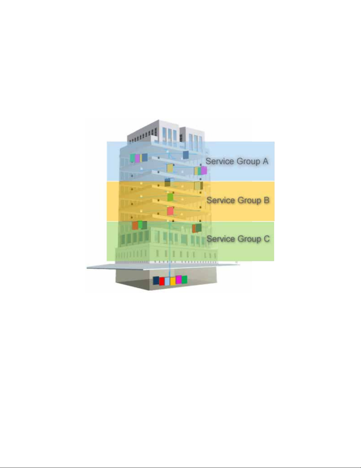
Figure 1-2 illustrates service distribution from the head-end to various locations on each remote floor. Each color represents a
specific service, where different combinations of services are distributed at various locations on the same floor according to
coverage requirements.
Figure 1-2. Illustration of Service Group Distribution
Corning Opt ical Communicat ions DRAFT User M anual I CM A- XXX-AEN I Page 13
Page 14
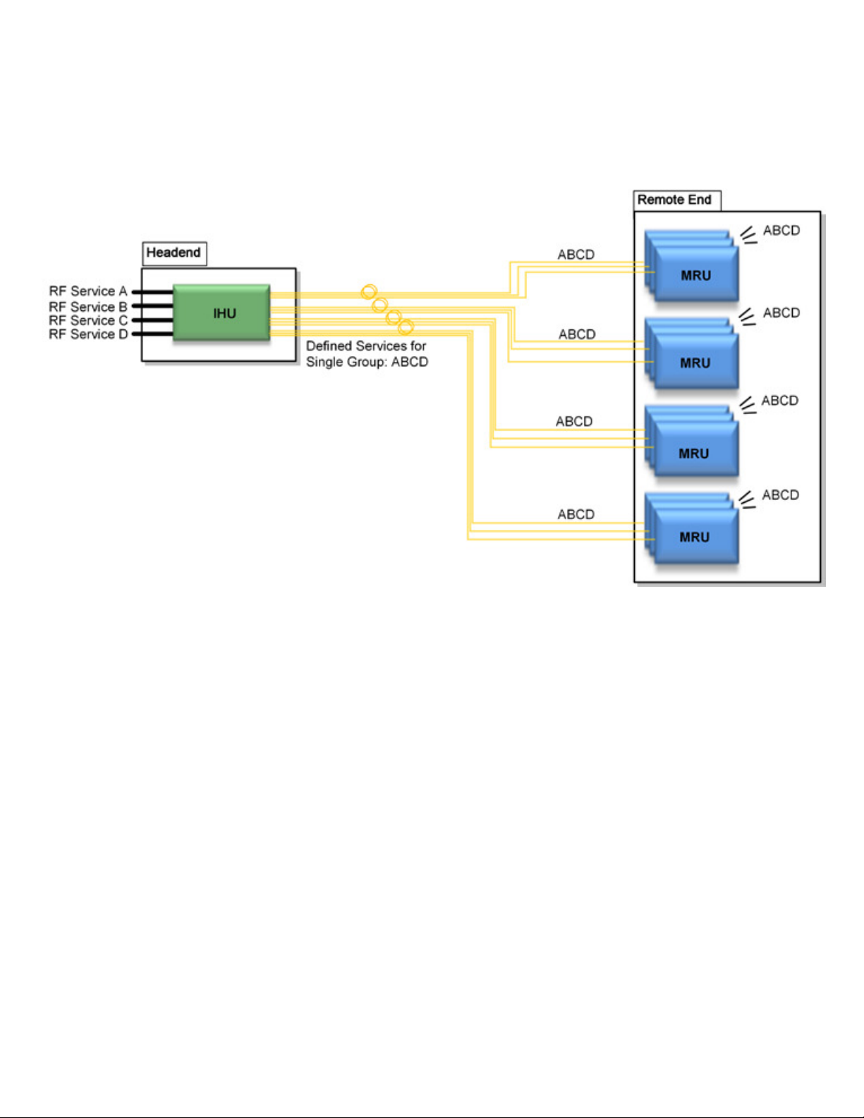
1.4.1 Service Distribution via One Service Group
In this example, all four services (A, B, C, and D) are routed to all remote units. In the illustrated topology, a single IHU
conditions the services and performs the RF-to-optic conversion after which all the configured services are routed to the remote
units for distribution over broadband antennas. Each IHU can support up to 24 remote-end units.
Figure 1-3. Distribution of a Single Service Group
Corning Opt ical Communicat ions DRAFT User M anual I CM A- XXX-AEN I Page 14
Page 15
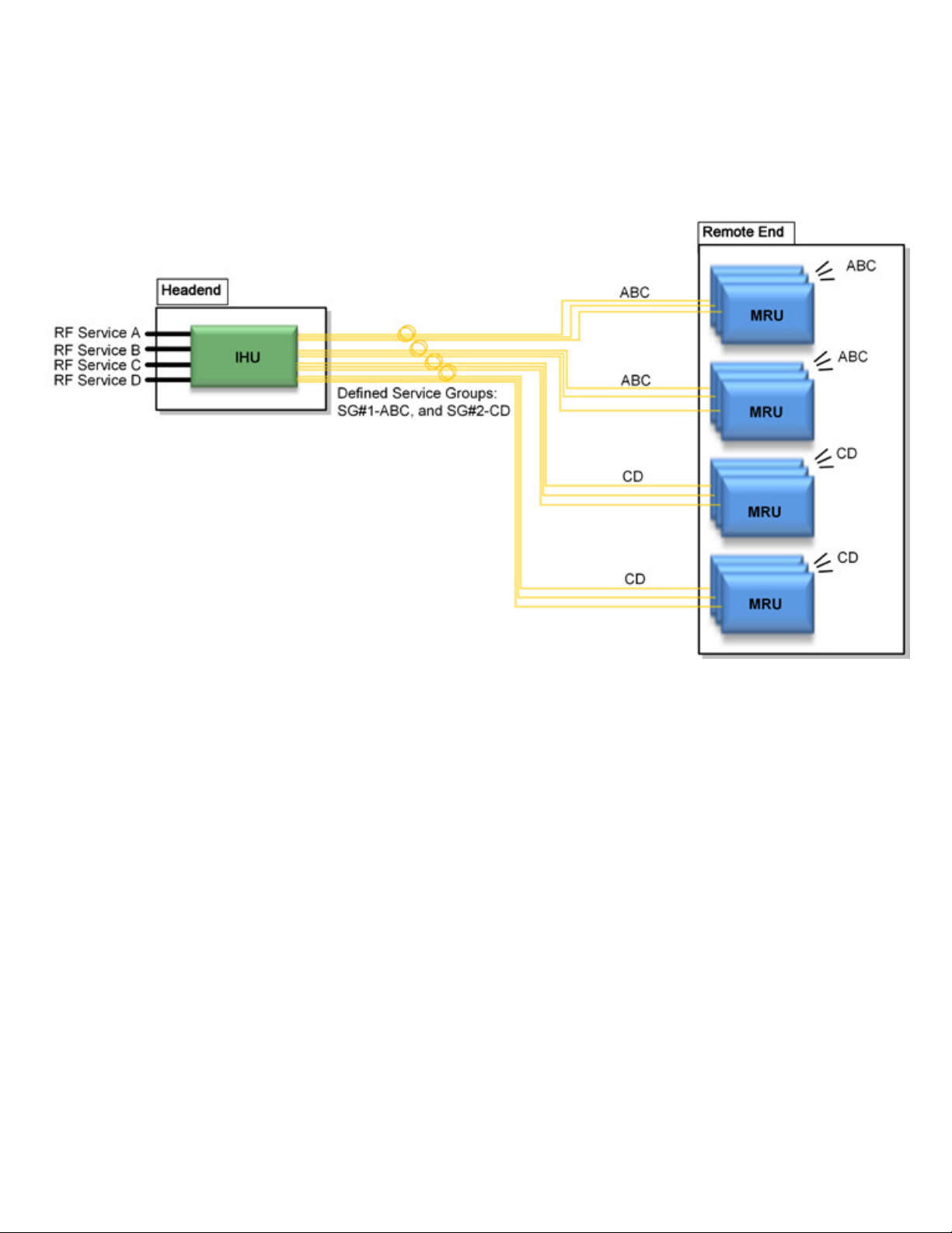
1.4.2 Service Distribution via Two Service Groups
In this example, two service groups are defined: SG#1: A,B,C and SG#2: C,D. When configuring a service group, the user
selects which services (according to RIMs) will be routed to which OIMs and then transferred over their optic links to their hosted
remote units for distribution.
Figure 1-4. Example of Distribution of Two Service Groups
Corning Opt ical Communicat ions DRAFT User M anual I CM A- XXX-AEN I Page 15
Page 16
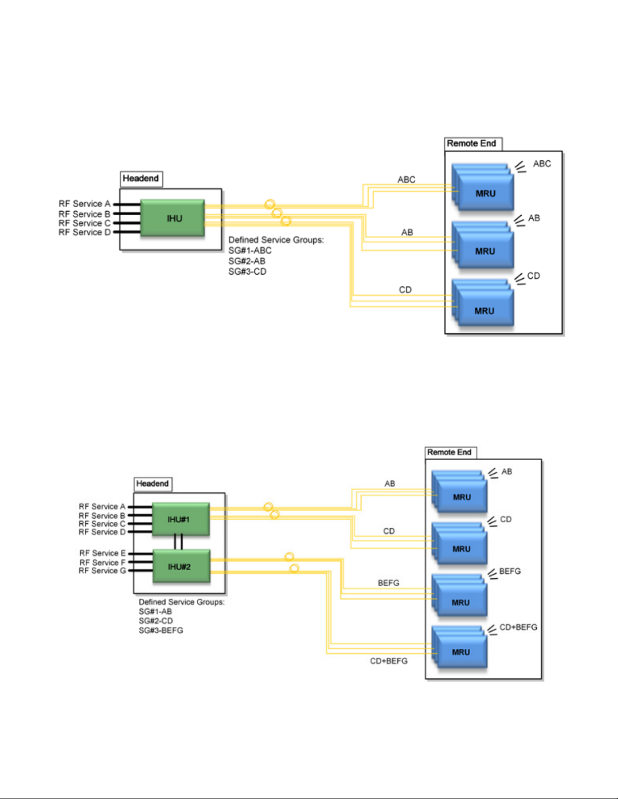
1.4.3 Service Distribution via Three Service Groups
In this example, three service groups are defined: SG#1: ABC, SG#2: AB, and SG#3: CD. Note that a service can be allocated
to any of the service groups at the same time. For example, services C and B are allocated to two of the service groups. The
services are routed to the OIMs for optic conversion. Each OIM can be configured to be included in any of the one, two or three
service groups in any combination and the corresponding services are routed from the OIM to its hosted remote-end units.
Figure 1-5. Example of Distribution of Three Service Groups
1.4.4 Service Distribution via Three Service Groups with Two IHUs
This example shows the distribution of three service groups with two IHUs. In this topology, the services routed via the two
IHUs can be grouped in any combination between the two, providing up to three service groups. Each OIM in the IHUs can be
configured to support any combination of service groups and the corresponding services are routed from to the hosted remote
units.
Figure 1-6. Example of Distribution of Three Service Groups with two IHUs
Corning Opt ical Communicat ions DRAFT User M anual I CM A- XXX-AEN I Page 16
Page 17
Tab
Description
Management
Displayed upon login by default. Displays general module information and
selected site devices.
manager are not considered events display.
Config
Set-up tool used for initial system set-up, commissioning of system devices
and adjustment procedure.
options and IP settings required for receiving traps.
Profiles
Enables creating complete system configuration and setup profile offline and
activating at a later time (software v1.8 and higher).
Location
Enables importing maps and icons to graphically display the geographical
for the system elements (software v1.8 and higher).
Multilink
Displays list of all of the setups configured in the same network and enables
access to authorized users (software v2.0 and higher).
Help
Provides access to online help
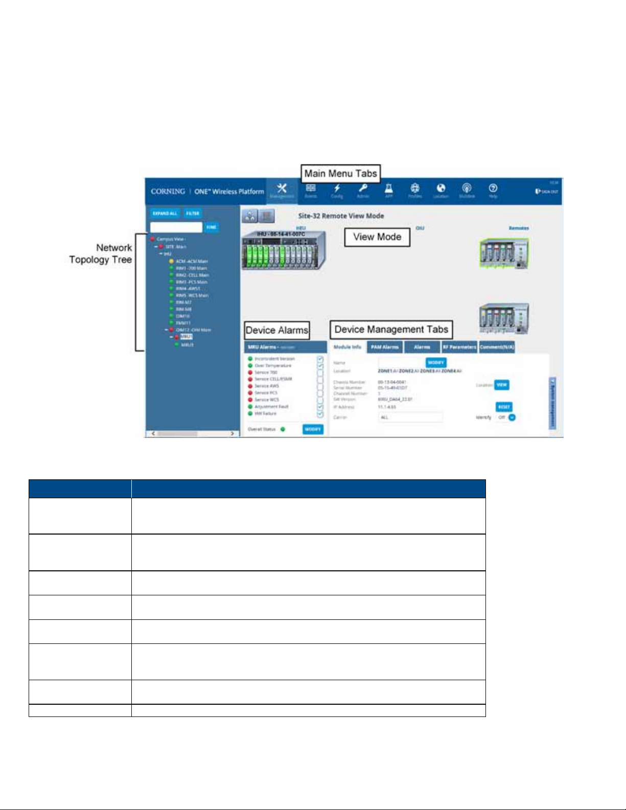
1.5 Web Management Application
The headend control module (HCM) enables centralized, system-level element management and
end-to-end, single source setup and management of the active RF components after their physical installation
provides c
omprehensive
.
Note: Refer to the Corning optical network evolution (ONE™) solutions HCM and Management GUI user manual for a complete
description of the Web management application.
Figure 1-7 shows the Management window, displayed by default upon login.
Figure 1-7. Example of Management Window (Software v2.2)
The main menu bar includes the following tabs:
device alarms and provides the configuration options for the available
Events Displays the events that occurred on the monitored devices and enables
generating reports. Configuration changes that are initiated by the network
Admin Provides administration options such as firmware upgrade, user management
location and types of sites as well as the floor plans and map power settings
Table 1-2. Main Menu Tabs
Corning Opt ical Communicat ions DRAFT User M anual I CM A- XXX-AEN I Page 17
Page 18
2 UNIT DESCRIPTIONS
2.1 Integrated Headend Unit (IHU) Description
The IHU is a compact unit which interfaces the RF sources (via RIMs), conditions the signals, performs the RF- to-optic
conversion of the received signal (via OIMs), and distributes the wireless RF services to the remote units over the fiber optic
infrastructure to the remote site. The IHU supports expansion connections to one additional IHU. Single source management is
provided by the HCM installed in one of the IHUs.
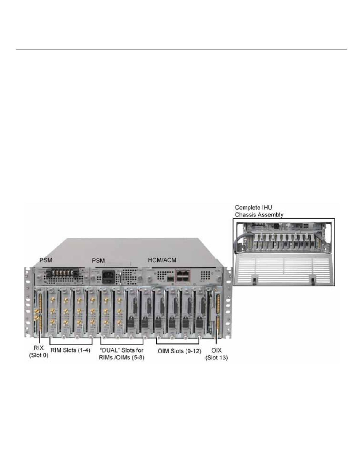
Figure 2-1 provides an example of an IHU with four RIM modules (for RF interface and conditioning), five OIU modules for RF to
optic conversion and routing to the fiber optic infrastructure, and three FMM modules (for topologies with campus connectivity).
The slots are color coded according to the type of modules that can be inserted in those slots:
• Red labeled slots – RIM slots
• Blue labeled slots – OIM slots
• White labeled slots – can host RIMs and OIMs
Note the following:
•
The IHU also includes a preassembled cable management tray with routed ERFC cable (shown in inset) used for connecting
the RIX and OIX.
•
The type and number of modules installed in an HEU chassis can vary according to the specific topology.
Figure 2-1. Example of IHU Front Panel with Installed Modules
The IHU performs the following main functions:
• Conditions (up to 8 including “Dual Slots”) RF sources to a level required for feeding to the OIMs.
• Enables the configuration of up to three RF service groups.
• Performs the RF-to-optic conversion of the RF services and forwards the services over the fiber optic infrastructure to the
remote site. Each OIU supports between 4-8 SM optic fibers.
For additional services or density, two IHU units can be cascaded, where both IHUs are managed from the headend control
module (HCM) installed in one of the units. The IHU installation procedure is detailed in Chapter 4.
Corning Opt ical Communicat ions DRAFT User M anual I CM A- XXX-AEN I Page 18
Page 19
Module
Description
Control
Module
RIM
RIX
PSM
OIM
2.1.4
OIX
Error! Reference source not found.
IHU hosts the following modules:
One of the following control modules is installed in each IHU:
• HCM (Headend Control Module) - one HCM per system. See section 2.1.1.1.
• ACM (Auxiliary Control Module) - installed in second IHU if installed. See section 2.1.1.2.
Radio interface module – up to 12 per HEU. See section 2.1.2.
RF expander module – interface to OIX. See section 2.1.3.
Power supply module – AC and DC models can be ordered. Each IHU supports two PSMs for
redundancy, where the same PSM type does not need to be installed in both slots. (Section
Note: If one module is installed, it must be installed in the left slot. If two modules are installed,
both must be powered on.
2.1.4).
Optical interface module - converts the RF to three optical links (see Section
Optical interface expander - interface to RIX (see Section
Table 2-1. IHU Modules
)
2.1.1 Control Module
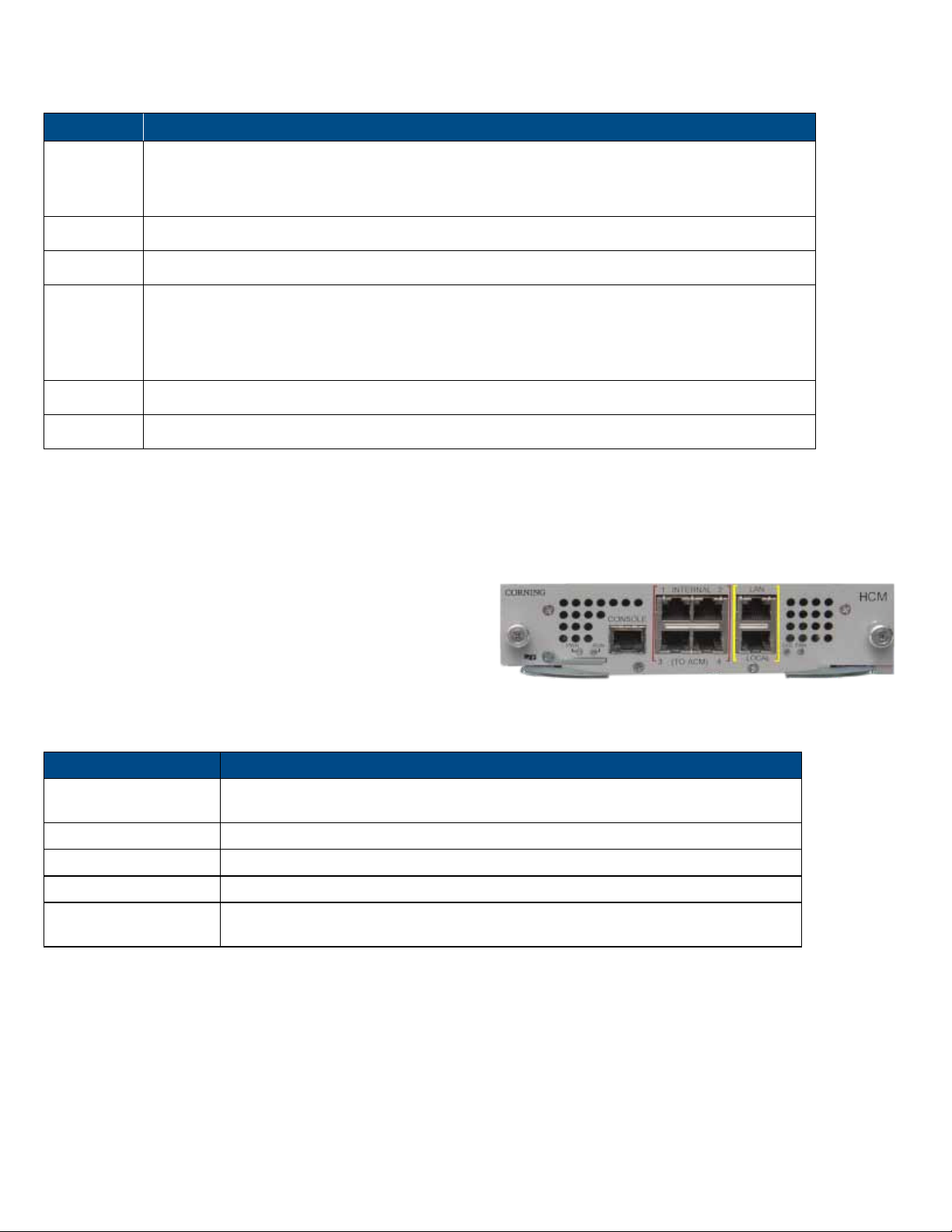
2.1.1.1 Headend Control Module (HCM)
This is a system control module that provides management
and control capabilities for all headend and remote-end
devices in a setup. One HCM is installed per setup in an IHU.
The HCM directly interfaces to the corporate LAN. It can be
connected to (up to) four auxiliary control modules (ACMs)
installed in additional headend units.
Table 2-2 and Table 2-3 provide a description of the HCM ports and LED status indicators.
Port Description
INTERNAL (TO ACM)
LAN RJ-45, 1 Gb Ethernet port - connects to the corporate LAN for remote management
Four RJ45, 100 Mb Ethernet ports - used for management of connected OIU
systems (and/or Auxiliary HEUs).
Figure 2-2. HCM Module
).
LOCAL RJ-45, 1 Gb Ethernet port - local configuration and management
CONSOLE RJ-45, serial port - local configuration for service personnel
SD Card Slot
Table 2-2. HCM Interface Ports
Corning Opt ical Communicat ions DRAFT User M anual I CM A- XXX-AEN I Page 19
Supports micro SD cards up to 32 GB (used for saving and importing configuration
files between different HEU chassis)
Page 20
LED
Description
Off – no power is supplied to the unit
PWR
RUN
SYS Steady green – overall status of the managed system is ok
FAN
Table 2-3. HCM LED Description
Steady green - power input detected by HCM
Blinking green – HCM Boot up sequence complete and module software up and
running
Off – no power supplied to the unit
Steady green – normal operation status for all fans
Red – fault indicated in at least one fan
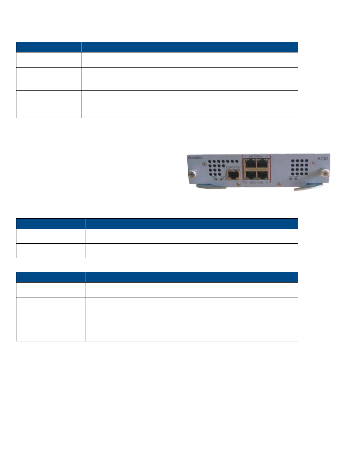
2.1.1.2 Auxiliary Control Module (ACM)
The ACM is installed in any additional IHU chassis (other than
the one in which the HCM is installed).
The ACM provides the interfaces for remote management and
control capabilities of the host chassis and connected remotes
via a local connection to the HCM (see section
Table 2-4 and Table 2-5 provide a description of the ACM ports and LED status indicators.
2.1.1.1).
Figure 2-3. ACM Module
Port Description
INTERNAL (TO HCM) Four RJ-45, 100 Mb Ethernet management ports - interface to HCM and/or other
ACMs
Console One RJ-45, serial port used for basic IP configuration and local connection for
service personnel
Table 2-4. ACM Ports Description
LED Description
PWR
RUN
SYS Steady green – overall status of the managed system is ok
FAN
Table 2-5. ACM LED Indicators Description
Steady green - power input detected by ACM
Off – no power is supplied to the unit
Blinking green – ACM Boot up sequence complete and module SW up and running
Off – no power supplied to the unit
Steady green – normal operation status for all fans
Red – fault indicated in at least one fan
Corning Opt ical Communicat ions DRAFT User M anual I CM A- XXX-AEN I Page 20
Page 21
Port
Description
LED
Description
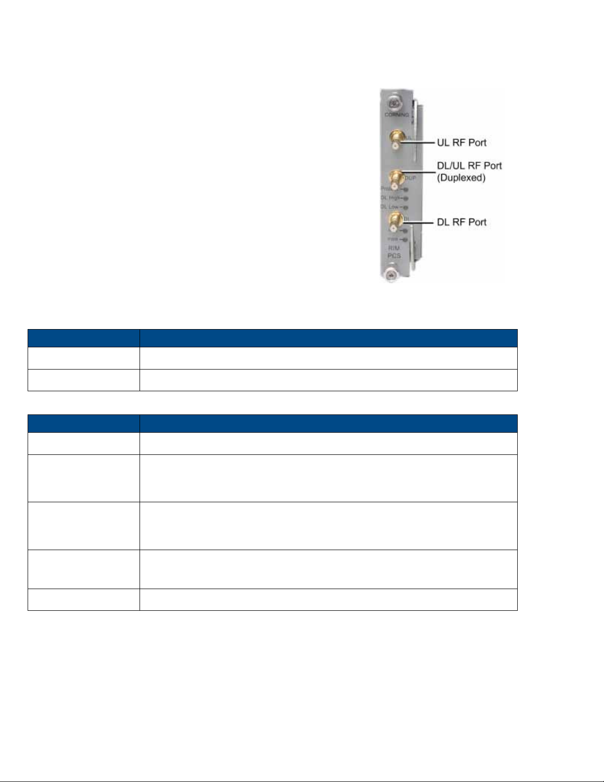
2.1.2 Radio Interface Module (RIM)
The RIM/RIM-M is a service specific RF conditioning module
that interfaces to the RF signal source. An IHU chassis can
support between 4-8 RIMs.
Each RIM supports both Simplex and Duplex RF connectors.
LEDs provide status indications on signal level and module
operation status.
Figure 2-4. RIM
Table 2-6 and Table 2-7 provide a description of the RIM ports and LED status indicators.
DL/UL UL and DL simplex connections to the RF signal source
DUP Duplexed UL and DL connection to the RF signal source
Table 2-6. RIM Ports Description
Protect N/A
DL High Provides indication on DL RF level in conditioner module:
• Off - DL RF input level in threshold range
• Steady red – signal is 3 dB above max. expected power
DL Low Provides indication on DL RF level in conditioner module:
• Off - DL RF input level in threshold range
• Steady red – no signal or 15 dB below max. expected power
RUN
PWR On - input power is within required range
Table 2-7. RIM LED Descriptions
• Blinking green - power on and module software has initialized and is up and
running
• Off - no power
Corning Opt ical Communicat ions DRAFT User M anual I CM A- XXX-AEN I Page 21
Page 22
Port
Description
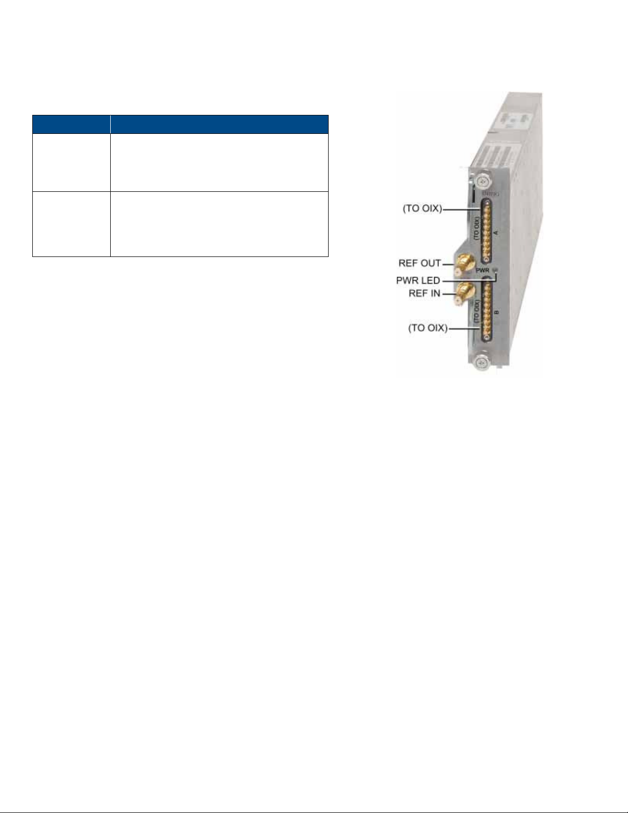
2.1.3 Radio Expander (RIX) Module
The RIX module provides the RF interface to the OIX module. Each
IHU includes one RIX.
Two 9 – pin connectors which serve as the RF
(TO OIX)
REF OUT/REF
IN
Table 2-8. RIX Ports Description
interfaces to the OIX. RIX supports
connections to two OIXs via an Expander cable
(ERFC).
Two QMA connectors used for reference clock
signal connections between RIX modules.
Note: The reference clock passes from the
Main HEU to all auxiliary chassis.
Figure 2-5. RIX Module Interfaces
Corning Opt ical Communicat ions DRAFT User M anual I CM A- XXX-AEN I Page 22
Page 23
Port
Description
LED
Description
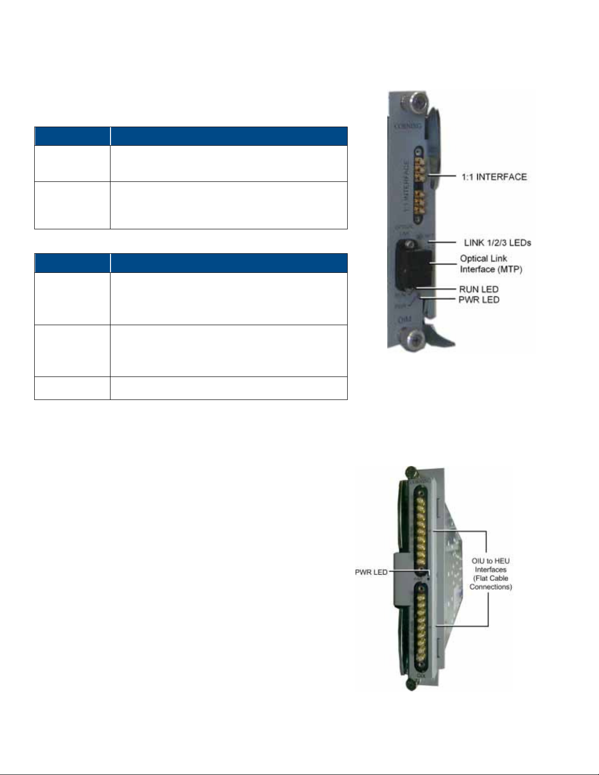
2.1.4 Optical Interface Module (OIM)
The OIM is a wideband RF to F/O (and vice-versa) media conversion
module. Up to 12 OIM units can be installed in each OIU, where each OIM
can support connections up to three remote units connections.
®
OPTICAL LINK
Female MTP
connection; SM fiber
Connector for optical interface
1:1
INTERFACE
Table 2-9. OIM Ports Description
Link 1-3
RUN
PWR Steady Green – Input power detected in OIM
Table 2-10. OIM LED Descriptions
Six pin SMP jack connector for 1:1 direct signal
transportation, three UL and three for DL enables (DL
and UL) broad band connection to each optical link
Steady Green - optical link power to/from the
connected remote is normal
Off - no optical power from remote detected
Blinking Green – OIM module software has initialized
and is up and running
Off – Power off
2.1.5 Optical Expander Module (OIX)
The OIX provides the RF interface to two RIX modules via two
9-pin connectors.
Figure 2-6. Optical Interface Module
.
Figure 2-7. OIX Interfaces
Corning Opt ical Communicat ions DRAFT User M anual I CM A- XXX-AEN I Page 23
Page 24
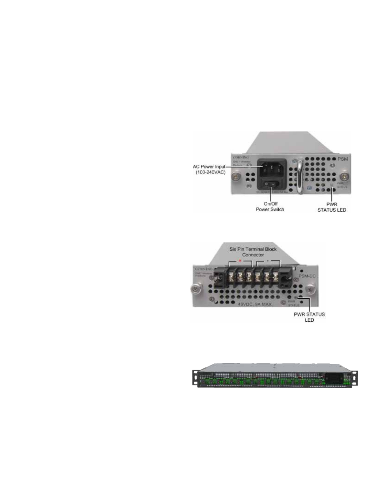
PSM-AC
PSM-DC
2.1.6 Power Supply Module (PSM)
Two types of power supply modules are available:
• PSM-AC: 100 – 240 VAC (power rating 300 W);
• PSM-DC: 48 V DC; 9 A maximum (power rating 300 W).
Note the following:
• Each IHU can support two PSMs, where the second PSM provides redundancy in case one of the supplies fails.
• In cases that a single power supply module is installed, it must be installed in the LEFT slot.
• Both types of PSM modules (AC and DC) can be installed in the same chassis (at the same time).
• If two PSM modules are installed, both must be connected to their respective power source and turned on at all times.
The PSM-AC includes an AC power connector, on/off switch
and power status LED.
Figure 2-8. PSM-AC
PSM-DC power source rating:
48 V DC; 9 A Max.; 300 W
The PSM-DC includes a six pin terminal block connector,
supporting up to three DC wire pairs.
Figure 2-9. DC Power Supply Module
2.2 Six Module DC Power Supply Unit (PSU6) Description
PSU6 is a compact, scalable DC enclosed power supply used
for feeding Corning optical network evolution (ONE™)
solutions elements.
Power outputs:
• Up to 12 outputs of 57 VDC
• 100 W per output
• Total power of 1200 W
Figure 2-10. PSU6 Front Panel
Refer to Section 7.8 for complete specifications.
Corning Opt ical Communicat ions DRAFT User M anual I CM A- XXX-AEN I Page 24
Page 25
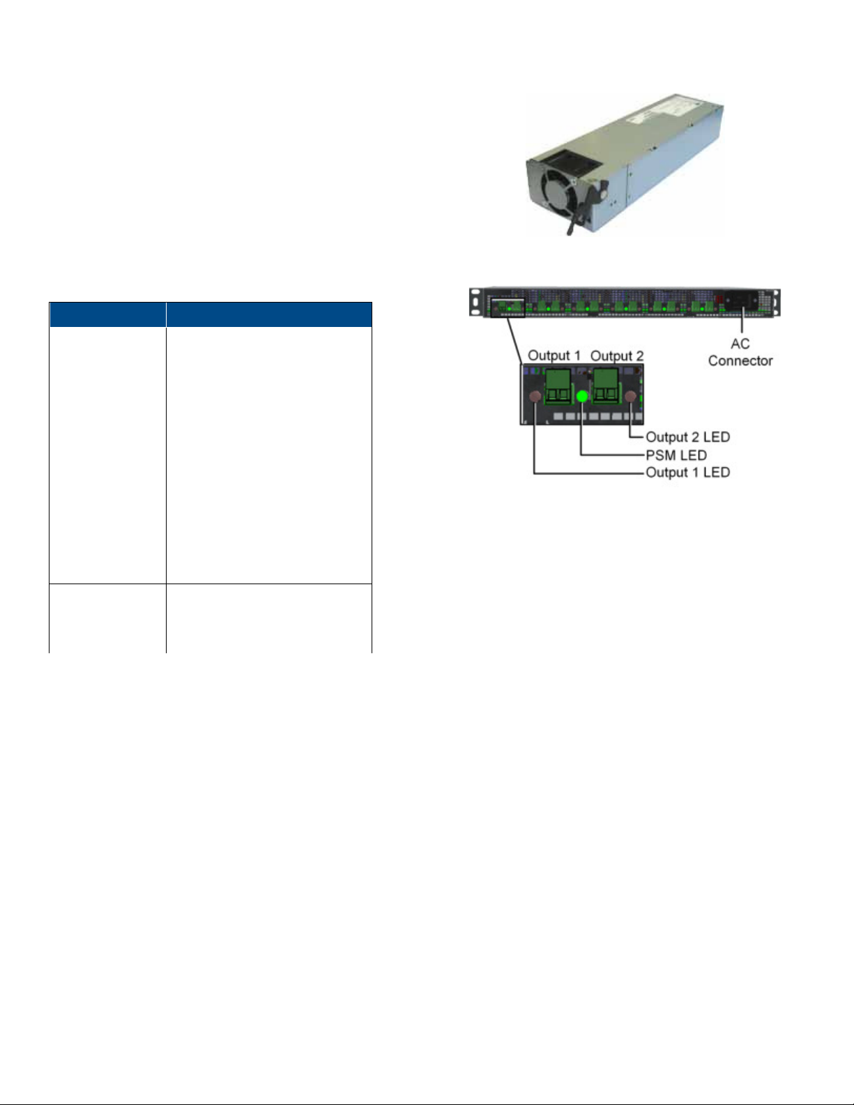
LED
Description
PSU6 supports up to six modules, where each module
provides two DC outputs. All interfaces are located on the front
panel. Modules are inserted and removed via the rear panel.
The status of each module is indicated by a dedicated LED:
PSM LED Green – power OK
Red - indicates one (or more)
of the following:
• Insufficient input power
• Problem with output load at
one or both PSM output
ports
• PSM over temperature
protection set
• Fan failure
Off in one PSM – PSM is off
Off in all PSMs – no power input
detected
Figure 2-11. PSU6 Power Supply Module
Figure 2-12. AC Input Power Connector and PSU6 LEDs
Output LED 1/2 Off – normal operation
Red – short circuit or overload
detected
Table 2-11. PSU6 LED Description
Corning Opt ical Communicat ions DRAFT User M anual I CM A- XXX-AEN I Page 25
Page 26
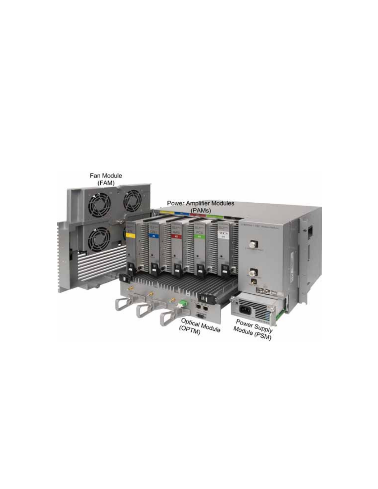
2.3 Mid-Power Remote Unit (MRU)
This section provides detailed descriptions of the MRU chassis and main modules and interfaces. This includes port and LED
interface descriptions. The MRU comprises the following main modules:
•
Power amplifier modules (PAM) – internal service specific power amplifier module that interfaces to an optical interface
module (OIM) at the headend site via a single-mode fiber pair and supports one service. MRU supports up to seven bands.
The PAM provides the additional amplification on the DL signals routed from the OIM towards the multiplexer; PAMs are
pre-installed in designated slots according to supported band.
Multiplexer – combines the UL and DL RF signals of the supported services in addition to external RF signal (future option
•
for connecting to external 2.5 GHz signal source) while providing the proper filtering into a single duplexed antenna port.
• Optical Module – includes the fiber optic, RF expansion and external alarm interfaces
• Power supply module (PSM) - local AC or remote DC power feed (model dependent);
• Fan module (FAM) – integrated fan module comprised of four fans which are also monitored via the web GUI
The MRU includes front panel interfaces (e.g. antenna, fiber optic connection and LED status indicators) as well as status
indicators per each internal module (which are accessed by opening the cabinet door. The following sections provide details on
the front panel and internal module interfaces.
Figure 2-13 MRU Main Modules
Corning Opt ical Communicat ions DRAFT User M anual I CM A- XXX-AEN I Page 26
Page 27

SMA RF ports for UL and DL connections to add-on unit (supporting any band
across the supported spectrum: 300 MHz to 3 GHz)
The MRU front panel includes the RF and fiber optic interfaces in addition to the system level status LEDs and service
maintenance ports. The internal PAM modules each include a PWR/STS LED.
Figure 2-14. MRU External Interfaces
Table 2-2 and Table 2-3 provide a description of the MRU interface ports and LED status indicators.
Port Description
ANTENNA PORT 4.3-10 Type RF duplexed RF antenna port
TEST PORT QMA coupling test port used for UL and DL measurements during system operation
2.5 GHz INPUT PORT N/A (Future option); 4.3-10 Type RF port for 2.5 GHz external RF source
GND Two-hole, standard barrel grounding lug
PSM Power Connector Model dependant:
AC models – AC connector connected to power source using provided AC power
cable only
DC models - two types of terminal block connectors:
• CLASS2 (default) – two “DC In” 8-pin terminal block connectors for remote feed:
one pair for each PAM ( total of five pairs) and one pair for the FAM+OPTM; one
RSV pair
• CLASS1 – one “DC-In” 2-pin terminal block for local plant feed
Exp. UL/DL
Corning Opt ical Communicat ions DRAFT User M anual I CM A- XXX-AEN I Page 27
Page 28

LED
Description
PWR
Steady green:
Required power is supplied to MRU chassis
Off:
No power input detected
green:
Rapid blinking
green:
“Identify” feature has been enabled via the management GUI
Off:
No power inpout detected
Steady green:
Normal operation; overall status OK
Steady red:
Indicates generated alarm in unit
rm
indicator.
FAM
Steady green:
All four fans are operating at normal speed (fan alarms clear)
Steady red:
Fault detected in at least one fan (fan alarm set)
LINK
Steady green:
Optical link level from optical module above normal threshold
Steady red:
Optical link level is lower than normal threshold
(PAM)
Steady green:
Power and status of power amplifier module OK. No alarms active.
Steady red:
One or more alarms are active.
Port Description
List. Mode N/A
OPTIC LC APC port for single-mode fiber optic connection
MGMT RJ45 Ethernet connection for MRU local management connection
External Alarms DB9 female external alarm connector for external dry contact alarm connections
Exp. RJ45 Ethernet connection for Add-On local craft
Table 2-12. MRU Interface Ports
RUN Blinking
STS
Blinking red: “Over temperature” alarm active.; Indicates temperature has exceeded
Note: Temperature alarm is set as first priority and overrides any other ala
Table 2-13. MRU LED Descriptions
Unit is running and operational
threshold (with door open)
Corning Opt ical Communicat ions DRAFT User M anual I CM A- XXX-AEN I Page 28
Page 29

Operating
Storage
Regulation/Standard
Category
Approval
3 INSTALLATION GUIDELINES
Note the following:
• It is assumed that the site survey and installation planning (including power requirements) have been completed.
• Specifications of remote units are described in the corresponding datasheets and installation manuals.
This chapter provides installation guidelines for the Corning optical network evolution (ONE
following installation rules are based on the assumption that the site survey and installation planning (including power
requirements) have been completed. This includes planning the distribution of antennas to provide the required coverage, as
well as planning the layout of the devices and cables in the telecom closet or shaft.
3.1 General System Specifications and Requirements
This section includes the environmental and physical specifications for the following units: HEU, OIU, IHU, CEU, ICU and
PSU6.
3.1.1 Environmental and Regulatory Specifications
3.1.1.1 Temperature and Humidity
The environmental specifications listed below are relevant to all Corning optical network evolution (ONE™) solution devices.
™
) IHU, PSU6, and MRU. The
Temperature 0°C to +50°C (32°F to 122°F) -20° C to 85° C (-4°F to 185°F)
Humidity 95% (non-condensing) 95% (non-condensing)
Table 3-1. Temperature and Humidity Specifications
3.1.1.2 Safety and Regulatory Approvals
The safety and regulatory specifications listed below are relevant to all Corning optical network evolution (ONE™) solution
devices.
Laser Safety
EMC
Safety
Table 3-2. Safety and Regulatory Approvals
FDA/CE 21 CFR 1040.10 and 1040.11 except for deviations pursuant to laser
notice no. 50 and IEC 60825-1
CE EN 301 489, EN55022, EN 61000
FCC 47 CFR Part 15, 22, 24, 27
UL 60950
IEC 60825-1:2007
IEC 60825-2:2010
CAN/CSA-C22.2 No.60950-1-03
Fire Safety UL 2043 (applicable for RAU5 only)
Corning Opt ical Communicat ions DRAFT User M anual I CM A- XXX-AEN I Page 29
Page 30

Unit
Description
Min-Max Voltage (VAC)
Max Power Draw
(Watts)
No. of
Units
Heat (BTU/hr)
Unit
Dimensions (H x W x D)
Rack Space
19-in (RU)
Weight: lbs [kg]
3.1.2 Power and Heat Specifications Summary
Table 3-3 provides the power, heat and rack specifications for the equipment installed in the headend/telco rooms.
IHU Integrated headend unit 100 – 220 300 1 1020
PSU6 Six Unit DC power supply unit
Table 3-3. Power and Heat Specifications
85 to 265
1200
(100 W per port)
1 512
(typical at 100 V in)
3.1.3 Dimensions, Weight and Rack Specifications of Units
Table 3-4 describes the physical specifications of the Corning optical network evolution (ONE™) solution units described in this
manual.
IHU 7 x 17.3 x 15.5 in
[177.8 x 440 x 394 mm]
PSU6 1.73 x 17.51 x 13.74 in
[44 x 445 x 349 mm]
4 Chassis: 30 lbs (14 kg)
Per RIM: 1.9 lbs (0.9 kg)
Per RIX: 1.54 lbs (0.7 kg)
Per OIM: 1.5 lb (0.7 kg)
Per OIX: 1.54 lb (0.7 kg)
ACM: 2.2 lb (1.0 kg)
PSM: 1.98 lb (0.9 kg)
1
Enclosure: 6.22 lb (2.825 kg)
Per PSM-I module: 0.8 lb (0.36 kg)
MRU
Table 3-4. Dimensions, Weight and Rack Specifications of Headend/Intermediate Units
10.5 x 17.5* x 15.75 in (266.7 x 445 x 400 mm)
*without rack brackets
6
Chassis without PAMs: 48 lbs (21.8 kg)
Each PAM: 4.7 lbs (2.15 kg)
3.2 Infrastructure Preparation
The following installation rules are based on the assumption that the site survey and installation planning (including power
requirements) have been completed.
3.2.1 Site Considerations
• The distance between the MRU service antenna and the coverage area should correspond to line of sight (LoS)
requirements for maximum coverage area.
• The maximum fiber path loss is 5 dB.
• The system delay of the optical system must be taken into consideration when there are neighboring BTS sites overlapping
in coverage.
Corning Opt ical Communicat ions DRAFT User M anual I CM A- XXX-AEN I Page 30
Page 31

3.2.2 Installation Location Requirements
• Mounting surface shall be capable of supporting the weight of the equipment.
• In order to avoid electromagnetic interference, a proper mounting location must be selected to minimize interference from
electromagnetic sources such as large electrical equipment.
• Working space available for installation and maintenance for each mounting arrangement.
• Ensure unrestricted airflow.
• Ensure grounding connector is within reach of the ground wire.
• Ensure a power source is within reach of the power cord and the power source has sufficient capacity.
• Where appropriate, ensure unused RF connectors are terminated.
• Do not locate the equipment near large transformers or motors that may cause electromagnetic interference.
• Reduce signal loss in feeder cable by minimizing the length and number of RF connections.
• Ensure the equipment will be operated within the stated environment (refer to Appendix A: Specifications or unit datasheet).
• Where appropriate, confirm available of suitably terminated grade of RF and optical fiber.
• Observe handling of all cables to prevent damage.
3.2.3 Safety Guidelines
Before installing the equipment review the following safety information:
• Follow all local safety regulations when installing the equipment.
• Only qualified personnel are authorized to install and maintain the Repeater.
• Ground specified equipment with the provided grounding bolt
• Do not use the grounding bolt to connect external devices.
• Follow Electro-Static Discharge (ESD) precautions.
• Use low loss cables to connect the antennas
3.2.4 Rack Safety and Installation Guidelines
3.2.4.1 Rack Safety Instructions
The following guidelines are relevant to the rack installed units. Review the following guidelines to help ensure your safety and
protect the equipment from damage during the installation.
• Only trained and qualified personnel should be allowed to install or replace this equipment.
• Verify that ambient temperature of the environment does not exceed 50°C (122° F)
• To maintain a low center of gravity, ensure that heavier equipment is installed near the bottom of the rack and load the rack
from the bottom to the top.
• Ensure that adequate airflow and ventilation within the rack and around the installed components so that the safety of the
equipment is not compromised. It is recommended to allow for at least about 2 cm of airspace between devices in the rack.
• Verify that the equipment is grounded as required – especially the supply connections.
3.2.4.2 Rack Installation Guidelines
• To maintain a low center of gravity, ensure that heavier equipment is installed near the bottom of the rack and load the rack
from the bottom to the top.
• Verify that the rack height can support the unit to be installed, where you may also want to consider future installations.
− IHU rack height = 4U
− PSU6 rack height =1U
− MRU rack height = 6U
3.2.5 Power Safety and Power Requirements
This section summarizes the power requirements of devices described in this manual.
3.2.5.1 Power Safety Instructions
Corning Opt ical Communicat ions DRAFT User M anual I CM A- XXX-AEN I Page 31
Page 32

SAFETY WARNINGS! When installing or selecting the power supplies:
• Use only the power cables (AC and DC) and any other relevant accessories provided with the unit to connect the power
supply to the system components.
• For MRU AC models – only use the provided AC power cable (straight, U.S 10 A ,UL, L = 1.8-2.5 m ,black,110 V ) to connect
the power supply to the MRU.
• Be sure to disconnect all power sources before servicing.
• Calculate the required power according to the requirements of the specific installation and then determine the configuration
of the power supplies. The required DC cables will then be determined by the selected PS configuration.
• Use only UL approved power supplies
• Install external over-current protective devices for the system according to the requirements described in section 3.1.2 -
Power and Heat Specifications Summary..
• Types of Power Supplies - Corning supplies various power supplies that can be installed in a rack or mounted on a wall,
depending on your configuration.
3.2.5.2 Types of Power Supplies
Corning supplies various power supplies that can be installed in a rack or mounted on a wall, depending on your configuration.
3.2.5.3 Circuit Breakers
Calculate the required fuse protection while referring to section 3.1.2 - Power and Heat Specifications Summary. Also, take into
account when installing fuse protections for the system that there may be other Corning system elements that require external
fuse protection.
Corning Opt ical Communicat ions DRAFT User M anual I CM A- XXX-AEN I Page 32
Page 33

Vertical
Horizontal
3.2.6 RF Coaxial Cable Guidelines
3.2.6.1 Considerations for Cable Type and Installation Procedure Guidelines
Note: The installer should be familiar with the ANSI/TIA/EIS-568 Cabling Standard guidelines.
• Observe the general cable installation procedures that meet with the building codes in your area.
• The building code requires that all cabling be installed above ceiling level (where applicable). The length of cable from the
risers to each antenna must be concealed above the ceiling.
• The cable must be properly supported and maintained straight using velcro cable ties, cable trays and clamps or hangers
every 10 feet (where practical above ceiling level).
Where this is not practical, the following should be observed:
− The minimum bending radius of the supplied ½” coax cable should be 7”.
− Cable that is kinked or has a bending radius smaller than 7” must be replaced.
− Cable runs that span less than two floors should be secured to suitably located mechanical structures.
− The cables should be supported only from the building structure.
• All cables shall be weather-resistant type
• The cable length is determined by the system installation plan. When calculating the cable length, take into account excess
cable slack so as not to limit the insertion paths.
3.2.6.2 RF Rules
• Use coax RG-223, 50 ohm, male-to-male N-type to QMA for RF connections from the RIMs to the BTS/RBS and to the
RAUs.
• When using the Corning system in an environment in which other indoor coverage systems are installed, it is recommended
(where possible) that the antennas are placed at least two meters apart
• When bending coax cables, verify that the bending radius does not exceed the coax specifications.
• Use a VSWR meter (i.e. Site Master or equivalent) for checking coax cables, including the antennas. (<2). The VSWR must
be measured prior to terminating the RAUs at the remote locations.
.
3.2.7 Fiber Optic Requirements
3.2.7.1 Authorized Optic Cables
The following specified optic cables are authorized for use with Corning optical network evolution (ONE™) products:
Plug & Play™ Plenum Optical cables
MTP Fiber Connectors
12 – 144 fibers
2-sided or 1-sided
Armored, non-armored
Composite Plenum Tether Assemblies
Fiber: LC APC, 2 – 24 fibers
Cu: 16 AWG, 14 AWG, 12 AWG; 2 – 12 Conductors
Armored, non-armored
3.2.7.2 Fiber Optic Rules
• Use only MTP® or LC APC connectors
• UniCam connectors can be used for field termination
• Use only fusion splice for connecting two fibers
• Use minimum splicing/connectors to achieve minimum losses on the fibers (< 0.5 dB)
• Use precaution while installing, bending, or connecting fiber optic cables:
− Fiber optic cable is sensitive to excessive pulling, bending and crushing forces. Consult the cable specification sheet for
the cable you are installing.
− Do not bend cable more sharply than the minimum recommended bend radius.
− Do not apply more pulling force to the cable than specified.
Corning Opt ical Communicat ions DRAFT User M anual I CM A- XXX-AEN I Page 33
Page 34

− Do not crush the cable or allow it to kink. Doing so may cause damage that can alter the transmission characteristics of
the cable. The cable may have to be replaced.
• Use an optical power meter and light source for checking the fiber optic cables
• Make sure the environment is clean while connecting/splicing fiber optic cables
• All fiber optic connectors should be cleaned prior to connecting to the system
• Fiber connector protective caps should be installed on all non-terminated fibers and removed just before they are
terminated.
• Pay special attention while connecting the LC APC connectors – ensure that you hear a “click”, indicating a secure
connection
• Never look directly into the end of a fiber that may be carrying laser light. Laser light can be invisible and can damage your
eyes.
3.3 Antenna Specifications and Guidelines
Determine the antenna installation configuration, according to the transmission and coverage requirements and the installation
site conditions.
3.3.1 Authorized Antennas and Required Specifications
• External antennas - no limitation on any vendor of available external antennas with respect to the following requirements:
− Omni Directional or directional
− Supported frequency range: wideband antennas supporting a range of 700 MHz to 2600 MHz
− Gain: up to 12.5 dBi
− Impedance: 50 Ohm
• Couplers – Use N-Male to N-Female broadband coupler separately ordered from Corning (P/N AK-1COUPLER-NM-NF)
or the equivalent:
− Broadband frequency: 300 – 3000 MHz
− -20 dB coupling (SMA coupling port)
− Maximum VSWR/return loss:12 dB
− Maximum insertion loss (dB): 0.2
• Number of antennas that can be connected (with cables/splitters) – it is not recommended to connect more than one
antenna per connector since 1:1 connectivity is reduced with each split.
• Types of couplers/splitters – depends on number of splits (not recommended)
Corning Opt ical Communicat ions DRAFT User M anual I CM A- XXX-AEN I Page 34
Page 35

4 IHU INSTALLATION
This chapter describes the installation for the IHU, PSU-6, and MRU equipment. A section is dedicated to general information
relevant for the installation of the HEU, OIU and IHU, followed by dedicated installation sections for each type of equipment.
Note: For specific guidelines on infrastructure planning, design and installation, please consult with a Corning product line
manager or Corning approved installer.
4.1 General Installation Information
Note the following information:
• The IHU chassis and modules are supplied separately and must be inserted by the user. Only the fan module is factory
installed in the chassis rear.
• The IHU is installed at the intermediate distribution frame (IDF), adjacent (or as close as possible) to each other to facilitate
the connections.
• The expander cable (ERFC) interconnecting the OIX and RIX modules are provided in lengths ranging from 16 to 59 in so as
to accommodate a range of HEU-OIU rack installation configurations.
• HCMs and ACMs are not hot-swappable.
• Hot-swappable modules: RIMs, OIMs, PSMs, FAMs, RIXs and OIXs.
• If a redundant power supply is provided, both supplies must be installed, connected to respective AC or DC power and
switched on.
• All components of a system installation are controlled and managed via a single HCM which is installed in the IHU chassis.
Note: The management connections for the Corning optical network evolution (ONE™) solution elements are detailed in the
HCM and Web management GUI user manual.
Corning Opt ical Communicat ions DRAFT User M anual I CM A- XXX-AEN I Page 35
Page 36

IHU Kit
Quantity
Item
RIM Kit (up to 8 according to order)
Quantity
Item
OIM Kit (up to 8 according to order)
Quantity
Item
RIX Module Kit
Quantity
Item
4.2 IHU Installation
4.2.1 Unpacking and Inspection
Unpack and inspect the cartons as follows:
1. Open the shipping cartons and carefully unpack each unit from the protective packing material.
2. Verify that all the items required for installing the chassis according to the items listed in the corresponding sections. If any of
the listed items are missing, contact your Corning representative.
3. Check for signs of external damage. If there is any damage, call your Corning representative.
Integrated headend unit chassis
Fan Module (S-FAM) – single unit hosting 4 fans
(installed in the chassis rear)
RJ45/RJ45 communication cable L=2m-2.15m (P/N 705900003) –
HCM management cable
Cable Management Tray - includes management tray with routed
ERFC cable and door sleeve
ERFC (Expander Cable) - RF interface cable between RIX and OIX
modules; 9 pin SMP to SMP connector; L=34 in
radio interface module (service specific) 1
1
1
1
1
Optical Interface Module (OIM) 1
MTP-LC APC Harness Cable (P/N 37HP900162-006F) - connector
for splitting fibers ( 6) leading from OIM to (FMU) Edge module
Radio Expander Module – expands the RF sources to the OIM
modules via the OIX
Pilot Transport Cable (P/N: PCKC47*) – Single QMA to QMA cable;
L = 47 in; used for passing reference clock signal connections
between RIX modules.
*Additional various lengths are available:
• PCKC20: L=20 in
• PCKC63: L=63 in
Corning Opt ical Communicat ions DRAFT User M anual I CM A- XXX-AEN I Page 36
1
1
1
Page 37

OIX Kit
Quantity
Item
PSM Kit (AC or DC modules - 1 or 2 kits according to order)
Quantity
Item
Controller Module Kit (HCM or ACM - according to order)
Quantity
Item
• PCKC79: L=79 in
OIU Expander Module - connects to the RIX Expander module;
1
provides RF interface between RIM and OIMs
PSM-AC: 100-240 VAC Power Supply Module including standard
1
IEC 60320-1 C13 cable
PSM-DC: 48 V DC Power Supply Module; 9 A Max.; Includes six pin
1
terminal block connector
HCM Kit (headend control module) – installed in IHU unit; enables
1
remote/local management of all hosted units
ACM Kit (auxiliary control module) – for system setups with two
1
IHUs; installed in second IHU unit; provides management
connections for the second IHU.
Table 4-1. Items Required for IHU Installation
Corning Opt ical Communicat ions DRAFT User M anual I CM A- XXX-AEN I Page 37
Page 38

4.2.2 (IHU Only) Assembling Cable Management Tray and RF Expander Connection
Note the following:
• The IHU cable management tray should be assembled before the unit is mounted onto the rack.
• The IHU modules can be inserted anytime before or after the management tray is assembled.
• The cable management tray consists of two items:
− Cable management tray with routed ERFC (RIX- to-OIX) cable
− Door sleeve
• A Phillips screwdriver is required.
4.2.3 Assembling the Cable Management Tray to the Chassis
Assemble the provided cable management tray to the chassis and connect ERFC Cable (routed through tray) as follows:
1. Assemble cable management tray to IHU chassis:
Figure 4-1. Assembling the Cable Management Tray
2. Connect ERFC Cable to RIX (Slot 1) 9-Pin connector and OIX (Slot 14) connector
ATTENTION! Manipulate the ERFC cable as shown on left in Figure 4-2 in order to properly connect the 9-pin connectors to the
RIX and OIX modules and so that the cable does not obstruct the module slots. Do not remove the cable ties holding the cable
in place!
Corning Opt ical Communicat ions DRAFT User M anual I CM A- XXX-AEN I Page 38
Page 39

Example of Routed Cables and Locked Tray
Figure 4-2. Overview of ERFC Cable Connection to RIX and OIX Modules
3. Route connected cables and lock tray.
Note: The tray pin must first be pulled towards the left and then
released into the hole.
Figure 4-4. Example of Routed Connection Cables and
Figure 4-3. Routing Connection Cables
Locked Tray
Corning Opt ical Communicat ions DRAFT User M anual I CM A- XXX-AEN I Page 39
Page 40

4.2.4 Assembling the Door Sleeve
Assemble the Door Sleeve as follows:
1. Pull down door cover.
Figure 4-5. Pulling Down Door Cover
Figure 4-7 and Figure 4-8 show open and closed views of the tray with assembled door sleeve.
2. Attach door to IHU chassis
Figure 4-6.Attaching Door to Chassis
Figure 4-7. Open View of IHU with Assembled Door
Corning Opt ical Communicat ions DRAFT User M anual I CM A- XXX-AEN I Page 40
Figure 4-8. Closed View of IHU with Assembled Door
Page 41

4.2.5 Mounting Chassis in 19-IN Rack
Note the following:
• The mounting procedure is the same for all chassis types (i.e. HEU, OIU and IHU).
• For IHUs – the IHU cable management tray, consisting of tray with routed ERFC cable and door sleeve, should be
assembled before the unit is mounted onto the rack. See Section 4.2.2.
• For HEU/OIU – the cable management tray can be assembled before after the chassis installation. See Section
Reference source not found. for details on how to assemble.
• Each chassis requires 4U rack height availability.
• Rack nuts and screws not provided (since that depends on the rack type).
To mount the chassis
1. Determine the location of the chassis in the rack while considering additional headend units and the lengths of the available
ERFC cables to be connected between the HEUs, OIUs and IHUs (provided with each HEU).
Note: In the IHU chassis, the ERFC cable is pre-routed through its’ cable tray
Figure 4-9 and Figure 4-10 illustrate the optimal rack installations for a maximum 4x4 HEU-OIU configuration in shared
and dedicated equipment scenarios.
Error!
Figure 4-9. HEU/OIU 4x4 Installation Diagram –
Dedicated
Corning Opt ical Communicat ions DRAFT User M anual I CM A- XXX-AEN I Page 41
Figure 4-10. HEU/OIU 4x4 Installation Diagram – Shared
Page 42

2. Referring to Figure 4-11 secure the units’ rack ears to the
rack frame as follows:
− Insert two screws half-way into the rack frame.
− Position the chassis on to the screws using the handles
and the bottom half slots of the rack ears.
− Secure the unit in the rack via all applicable bracket
holes using the appropriate rack nuts and screws.
Figure 4-11. Installing Chassis in Rack (shows HEU as
example)
Corning Opt ical Communicat ions DRAFT User M anual I CM A- XXX-AEN I Page 42
Page 43

IMPORTANT!
slot.
Error! Reference source not
found.
Error! Reference
source not found.
13, so that expander modules are
Version 2.0 and higher of
4.2.6 Installing Modules
Note: The HEU, OIU and IHU chassis are similar, whereas the managed modules vary depending on chassis type. The slot
locations for the control module, PSMs and expanders are the same for all chassis. Chassis slots are 100% mistake proof.
4.2.6.1 Module Locations in Chassis
Module Quantity Comment Examples of Occupied Chassis
Control
Module
PSM 1 - 2
Expander 1 - 2
1
• Headend control module (HCM) – one per
system; installed in an HEU or IHU.
• Auxiliary control module (ACM) – installed in
OIUs and in any additional HEU or IHU.
• For installations with one PSM module – install
module in left most slot.
• For installations with two PSM modules
(redundancy) – remove blank panel from
middle slot and insert additional PSM module.
• For HEU – RF expander modules (RIX) are
installed in Slot 1* and Slot 14*
• For OIU – optical expander modules (OIX) are
installed in Slot 1* and Slot 14*
Figure 4-12. Example of Occupied HEU
• For IHU – RIX module installed in Slot 1* and
OIX module installed in Slot 14*
• In installations with only one expander, the
unoccupied expander slot must be terminated
with an ETM.
ETM 1
RIM For HEU:
1 – 12
For IHU:
8
OIM
For OIU:
1 – 12
For IHU:
8
The RIX and OIX) are similar in
appearance but are NOT
INTERCHANGEABLE. Each expander
module is indicated as RIX or OIX on the
bottom of the module.
• Relevant if only one RIX module is installed in
the chassis.
• It is required to install the ETM in the empty RIX
• In HEU - installed in Slots 2 – 12*
• In IHU – installed in RIM Slots 2-5 and can be
installed in Dual Slots 6-9.
• No need to terminate unoccupied RIM slot
(leave blank panel).
• A RIM slot can be occupied by an FRM module
(see Section
for details on FCM solution).
• In OIU - installed in OIU Slots 2 – 12*.
• In IHU – installed in OIU Slots 10-13 and can be
installed in Dual Slots 6-9
• It is not necessary to terminate unoccupied
OIM slot (leave blank panel).
• An RIM slot can also be occupied by an FMM
module (see Section
for details on FCM
solution).
Figure 4-13. Example of Occupied OIU
Figure 4-14. Example of Occupied IHU
*Future chassis may be numbered from 0in Slots “0” and “13” and RIMs/OIMs in Slots 1-12.
management GUI display chassis numbering as “0-13”.
Table 4-2. Module Locations in Chassis and Installation Comments
Corning Opt ical Communicat ions DRAFT User M anual I CM A- XXX-AEN I Page 43
Page 44

4.2.6.2 Installing the Chassis Modules
To install modules
1. Remove blank panels of relevant slots
2. For modules with ejectors (i.e. RIM, OIM, expander modules, FMM/FRM and control module) - ejectors should be
completely open when inserting in dedicated slot. Figure 4-15 and Figure 4-16 show examples of module type captive
screws and ejectors.
3. Slide modules in the relevant slots (refer to module locations described in Table 4-2 and then push in until it clicks into the
backplane.
4. (Where relevant) close ejectors and on all modules, tighten captive screws. Figure 4-15 and Figure 4-16 show examples of
module type captive screws and ejectors.
Figure 4-15. Control Module Ejectors and Captive Screws Figure 4-16. RIM Ejectors and Captive Screws
4.3 Grounding Chassis
Grounding connections are the same foe all chassis types.
Connect the ground via the two-hole, standard barrel grounding lug
located on the chassis rear panel (see Figure 4-17):
• Use stranded copper wire conductors
• 10-14 AWG
• Holes - 1/4 inch
Figure 4-17. Grounding Lug (Chassis Rear)
4.4 RF Connections
4.4.1 RIM Connections to RF Source
Corning Opt ical Communicat ions DRAFT User M anual I CM A- XXX-AEN I Page 44
Page 45

For each service specific RIM - connect (simplex or duplex) RF QMA
connectors to the service providers’ external RF source. See
Figure 4-18.
Figure 4-18. RIM RF Source Interfaces
Corning Opt ical Communicat ions DRAFT User M anual I CM A- XXX-AEN I Page 45
Page 46

4.4.2 RF Expander Connections
Note the following:
A single IHU supports expansion connections as follows:
• To one additional IHU unit
• To one HEU and one OIU
To connect to an additional IHU
Note: Only the bottom OIX and RIX connectors of each IHU are free; the top OIX and RIX connectors should have already been
connected to the ERFC connector from the cable management tray (Section
Referring to Figure 4-19 and using the appropriate length ERFC cable length, interconnect the OIX and RIX (bottom)
connectors of both IHUs:
• From RIX of IHU #1 to OIX of IHU #2 ;
Main IHU OIX to Auxiliary IHU RIX;
4.2.2).
Figure 4-19. RIX to OIX Connections - Two IHUs
Corning Opt ical Communicat ions DRAFT User M anual I CM A- XXX-AEN I Page 46
Page 47

REF
OUT
REF IN
4.4.3 Pilot Clock Connections
Pilot clock connections are required in installations with two IHUs. It is required to interconnect the REF IN and REF OUT of the
RIX modules installed in both IHUs.
• Referring to Figure 4-20
(PCKC47 provided with each RIX) to connect the
and
chassis.
, use the QMA/QMA jumper cables
ports of the RIX modules in the IHU
Note: The REF IN and REF OUT pilot clock ports must be
connected in a closed loop.
Figure 4-20. Example of Pilot Clock Connections between
Two IHU Units
4.5 IHU Fiber Connections
The fiber connections are performed for the OIMs using the provided
Corning MTP-LC APC Harness Cable:
• Connect the cable MTP® connector to the OIM MTP connector
• Remove the protective plastic covers and (noting the numbering
1/2/3), connect the three LC APC connection fibers to the FMU
Edge module LC APC connections. See Figure 4-21.
Figure 4-21. OIM Fiber Connections
Corning Opt ical Communicat ions DRAFT User M anual I CM A- XXX-AEN I Page 47
Page 48

To connect the management connections
To connect the AC Power to the PSM-AC
4.6 Management Connections
Note: RJ-45/RJ-45 management cable is provided with each IHU.
1. Connect the HCM module LAN port to the corporate LAN using
the provided RJ45/RJ45 communication cable. See Figure 4-22.
2. For system setups with two IHUs:
From HCM INTERNAL port to the ACM INTERNAL port (any of
the four ports can be interconnected). Refer to Figure 4-22.
4.7 Power Connections and Power Up
Note the following:
Figure 4-22. HCM LOCAL Port to ACM Port LOCAL
Management Connection
• PSM-DC can be installed and activated simultaneously in the same chassis along with a PSM-AC module.
• For installations with two PSMs, both modules must be:
− Connected to their respective power source (AC or DC)
− Switched on to begin system operation
− Turned on at all times after installation
4.7.1 AC Power Connection (PSM-AC)
1. Connect power cable (100-240 VAC) supplied with
module to the PSM-AC input connector and to the AC
outlet and switch on. See Figure 4-23
2. Verify that the Power Status LED on each PSM is GREEN.
Figure 4-23. PSM-AC LEDs
Corning Opt ical Communicat ions DRAFT User M anual I CM A- XXX-AEN I Page 48
Page 49

To wire and connect the DC power
4.7.2 DC Power Connection (PSM-DC)
IMPORTANT! Verify that the DC power source is off before connecting the wire pairs!
Note the following:
• PSM-DC power source rating: 48 V DC; 9A max.
• The PSM-DC (see Figure 4-24) is provided with six
terminal rings (PN: 708A043001), type PMNF2-3R-C or
PMV2-3RB-3K (depending on availability)
• Type of terminal ring crimped onto DC wires – PANDUIT
ring terminal:
− Compatible wire size: 1.5 – 2.5mm² wire
− Range 14 AWG to 16 AWG
− M3 stud size
• No. of required wire pairs:
− Remote feed - three pairs; maximum 100 W per pair
− Local Plant feed - two pairs; maximum 100 W per pair
• Max. current consumption per pair:
− Remote feed = 1.55 A
− Plant feed = 4.65 A
Figure 4-24. DC Power Supply Module
1. Referring to Figure 4-25, crimp the provided terminal rings
onto the DC wire pairs.
IMPORTANT! Make sure to use an appropriate crimper.
Do NOT use a pair of pliers!
2. Referring to Figure 4-26, connect crimped terminal rings
to DC connectors.
IMPORTANT! Verify that the DC power source is off
before connecting the wire pairs!
3. For optimal cable management, route all wire pairs to the
left side of the rack
4. Turn on DC source and verify that power status LED is
green.
Figure 4-25. Crimping the Terminal Rings onto the DC Wire
Figure 4-26. Connecting PSM-DC Wire Pairs
Figure 4-27. Connected DC Wire Pairs and Green Power LED
Corning Opt ical Communicat ions DRAFT User M anual I CM A- XXX-AEN I Page 49
Page 50

4.8 Verifying Normal Operation
After powering up, verify that the HCM/ACM LEDs (see Figure 4-28) indicate normal operation. If the RF source is operational,
also verify that the RIM LEDs (see Figure 4-30
Note: The LEDs are the same for HCM and ACM modules.
HCM LED Description
PWR Steady green - power input detected by module.
RUN Blinking green – module software up and running
SYS Steady green - overall status of the managed system
is OK
FAN Steady green – normal operation status for all fans
Table 4-3. HCM/ACM LED Descriptions
LED Description
PWR Steady green - power input detected by module.
) indicate normal operation.
Figure 4-28. HCM/ACM LEDs
RUN Blinking green – module software up and running
SYS Steady green - overall status of the managed system
is OK
FAN Steady green – normal operation status for all fans
Table 4-4. ACM LED Descriptions
RIM LED Description
Protect N/A
DL High Off - DL RF input level in threshold range
Steady red – DL RF input level is 3 dB above
maximum expected power
DL Low Off - DL RF input level in threshold range
Steady Red - DL RF input level is 15 dB below
maximum expected power
RUN Blinking green - RIM module software has initialized
and is up and running
Off – power off
PWR Steady green - input power is within required range
Figure 4-29. HCM/ACM LEDs
Table 4-5. RIM LED Descriptions
Corning Opt ical Communicat ions DRAFT User M anual I CM A- XXX-AEN I Page 50
Figure 4-30. RIM LEDs
Page 51

OIM LED
Description
LINK 1/2/3 Steady green - optical link power to/from the
connected remote is normal
Blinking green - optical power from remote is lower
than required
RUN Blinking green - module software has initialized and
is up and running
Off – power off
PWR Steady green - power input detected in OIM
Table 4-6. OIM LED Descriptions
Figure 4-31. OIM LEDs
Corning Opt ical Communicat ions DRAFT User M anual I CM A- XXX-AEN I Page 51
Page 52

PSU6 Kit
Quantity
Item
Power Supply Module Kit (1 to 6 according to
order)
Quantity
Item
5 PSU6 INSTALLATION
This chapter describes the installation procedures for the PSU6.
5.1 PSU6 Installation
The PSU6 enclosure includes the DC connectors and power LEDs, and supports up to six power supply m odules (PSMs). The
PSU6 supports Corning optical network evolution (ONE™) solutions remotes and can also power the following specified
network int erface devices (NIDs):
®
• Tellabs™ - P/N Tellabs
• Zhone® - P/N ZNID-GPON-2624P-00
• Antaira® - P/N LMP-0601G-SFP-T
5.1.1 Items Required for PSU6 Installation
The follow ing kits and included it ems are required for installing the PSU6. I f any of the listed items are missing, cont act your
Corning repr esentative.
PSU6 1
AC power cable US plug, 90 degree, length 1.8
m-2.5 m
709GP ONT
1
Wall mount bracket 2
DC terminal block; two pole with screw for wire
(Manufacturing PN: Dinkle MP/N
2ESDV-02P)
Note: The DC terminal blocks are pre-inserted
into the units’ DC connectors.
Power supply module 1
Table 5-1. Required Kits for PSU6 Installation
12
Corning Opt ical Communicat ions User M anual I CMA- 490-AEN I Page 52
Page 53

5.1.2 Installing the Power Supply Module
Note the following:
• Modules can be inserted either before or after enclosure is mounted.
• The power supply modules are hot-swappable and can be installed/extracted either before or after power-up.
To install the power modules
1. With the lever up, slide the power supply module into one of the six slots on the PSU6 enclosure rear (Figure 5-1).
Figure 5-1. Inserting Power Supply Module
2. Push in the module until it is flush with the chassis.
3. Secure by pulling the lever downward until it “clicks" and the module is flush with chassis rear. See Figure 5-2
Figure 5-2. Securing PSM in Slot
Corning Opt ical Communicat ions User M anual I CMA- 490-AEN I Page 53
Page 54

5.1.3 Mounting PSU6
The PSU6 can be mounted in 19-in communication rack or on a wall – appropriate brackets provided for both mounting options.
5.1.3.1 Rackmount
Mount the PSU6 in the 19-in communication rack and secure the rack brackets to the rack uprights using appropriate rack
screws.
5.1.3.2 Wall Mount
To mount the PSU6 on a wall
1. Remove the rack mounting brackets and set the screws aside.
Figure 5-3. PSU6 Rack Bracket(s) for Removal
2. Using the four screws (previously set aside), assemble the wall mount brackets onto the sides of the PSU6 so that the unit
can be mounted belly-to-wall. See Figure 5-4.
Figure 5-4. DC Assembling Wall Mount Brackets
Note the following
• The unit should be mounted on the wall with the DC connectors facing sideways. See Figure 5-5.
Corning Opt ical Communicat ions User M anual I CMA- 490-AEN I Page 54
Page 55

Figure 5-5. Mounting Direction on Wall
• Make sure that there is enough space at the rear to insert/extract the PSMs.
3. Using the wall mount bracket keyholes as a guide, mark the holes to be drilled on the wall.
4. Insert appropriate bolts and mount unit.
5.1.4 Grounding
Note: For wall-mount installations – use grounding lug from previously removed right rack bracket.
The grounding connection is performed via a two-hole, standard barrel grounding lug located on the PSU6 front-left panel.
Required tools and components
The following additional (not supplied) tools and components are required for connecting the system ground:
• Grounding wire - grounding wire should be sized according to local and national installation requirements. The provided
grounding lug supports 14 AWG to 10 AWG stranded copper (or 12 AWG to 10 AWG solid) wire conductors.
Note: The length of the grounding wire depends on the proximity of the switch to proper grounding facilities.
• Phillips-head screwdriver
• Crimping tool to crimp the grounding wire to the grounding lug
• Wire-stripping tool to remove the insulation from the grounding wire
Corning Opt ical Communicat ions User M anual I CMA- 490-AEN I Page 55
Page 56

To wire the DC
To ground PSU6
1. Use a wire-stripping tool to remove approximately 0.4 inch (10.9 mm) of the covering from the end of the grounding wire.
2. Insert the stripped end of the grounding wire into the open end of the grounding lug.
Figure 5-6. PSU6 Grounding Connection
3. Crimp the grounding wire in the barrel of the grounding lug. Verify that the ground wire is securely attached to the ground lug
by holding the ground lug and gently pulling on the ground wire.
4. Prepare the other end of the grounding wire and connect it to an appropriate grounding point at the site to ensure adequate
earth ground.
5.1.5 DC Wiring Connections
Each installed PSM supports two DC outputs (terminal block pre-inserted) with the following specifications:
• Voltage: 57 v constant
• Maximum current: 1.7 A
• Power: 100 W
1. Identify the positive and negative terminals on the feed positions
as indicated on the PSU6. The wiring sequence is positive to
positive and negative to negative as shown in Figure 5-7.
2. Open the terminal block screw above the negative feed position
and then insert the exposed black wire (negative feed) into the
terminal block.
3. Torque the terminal block captive screw (above the installed wire
lead), using a ratcheting torque screwdriver. Recommended
torque is 0.51N•m.
4. Repeat for remaining positive feed (exposed red wire).
CAUTION! Secure the wires coming in from the terminal block so
that they cannot be disturbed by casual contact. For example,
use tie wraps to secure the wires to the rack.
5. Connect the DC wiring to the remote-end units (DC connections
on the remote-end side are described in the quick installation
sheet provided with each unit).
Figure 5-7. DC Wiring Connections
5.1.6 Power-up
Corning Opt ical Communicat ions User M anual I CMA- 490-AEN I Page 56
Page 57

LED
Description
Recommended Action
1. Connect the PSU6 AC power connector (front panel) to the AC
power outlet using the provided power cable.
The AC Input power specifications are as follows:
• Voltage
range:
85 to 265 VAC; 47 – 63 Hz. via IEC socket;
Rated voltage (for safety approval):
100-240 VAC, 50-60 Hz.
• Current:
Maximum input current at 85 VAC is 16.8
amp for six PSMs
• Power
>0.925 at maximum load
factor:
• Efficiency:
For 100 VAC input voltage: 86% minimum
at 25°C and 85% minimum at 55°C
Figure 5-8. AC Input Power Connector and PSU6
For 220 VAC input voltage: 88% minimum
at 25°C and 86% minimum at 55°C
2. Verify normal operation for each PSM by monitoring the PSM LEDs.
Each PSM has three LEDs – one power LED (per PSM) and two output LEDs.
PSM LED Green – power OK -
LEDs
Red - indicates one (or more) of the
following:
• Insufficient input power
• Problem with output load at one or both
PSM output ports
• PSM over temperature protection set
• Fan failure
Off in one PSM – PSM is off
Off in all PSMs – no power input detected
Output LED 1/2
Off – normal operation -
Red – short circuit or overload detected. Disconnect the load and then re-connect. If
Table 5-2. PSU6 LED Descriptions
-
-
Check power source
the problem continues the load may be
faulty and may need to be replaced.
Corning Opt ical Communicat ions User M anual I CMA- 490-AEN I Page 57
Page 58

Kit
Item Description
Quantity
6 M RU INSTALLATION
6.1 MRU Indoor Installation
6.1.1 Unpacking and Inspection
Unpack and inspect the cartons as follows:
1. Open the shipping cartons and carefully unpack each unit from the protective packing material.
2. Verify that all the items listed in Table 6-1 are included in the MRU package. If any of the listed items are missing, contact
your Corning representative.
3. Check for signs of external damage. If there is any damage, call your Corning representative.
MRU Mid-power remote unit
1
Note: See ‘Appendix B: Ordering Information for MRU part
numbers.
Hosted Modules
(pre-installed)*:
AC power cable (AC
models only)
Rack ears for 19-in rack (factory assembled onto sides of
MRU)
Table 6-1. MRU Kit
Service specific power amplifier
modules (PAMs) – pre-installed
according to ordered configuration
Fan module (FAM) 1
AC or DC (model dependent) power
supply module (PSM)
Cable, power, straight, USA 10A ,UL,
L=1.8-2.5m ,black,110V
1 - 5
1
1
2
* ATTENTION! In the event that a PAM or the OPTM needs to be removed from the chassis, make sure to first press the release button on the module and
then pull out using the handle. Any attempt to pull out the module without first releasing may cause damage. Refer to Section
found.for more details.
Corning will not be liable for damage of products resulting from improper handling during installation or repair.
Error! Reference source not
Corning Opt ical Communicat ions User M anual I CMA- 490-AEN I Page 58
Page 59

6.1.2 Mounting the MRU
The MRU supports two types of mounting installations:
• 19 – in rack installation ( see Section 6.1.2.1)
• Wall mount installation (see Section 6.1.2.2)
• Outdoor installation – the MRU can be installed in a separately ordered outdoor enclosure; Refer to Section 0 for
instructions on how to install the MRU in a Purcell cabinet (Flexsure®12-2420).
6.1.2.1 Rack Installation
Note the following:
• MRU chassis requires 6U rack height availability
• Rack nuts and screws not provided
To install MRU in rack
Determine the location of the MRU in the rack while considering additional units (e.g. power supply).
1. Referring to Figure 6-1, secure the units’ rack ears to the rack frame as follows:
− Insert two screws half-way into the rack frame (one on each side)
− Position the bottom half slots of the chassis rack ears on to the screws
− Secure the unit in the rack via the remaining applicable bracket holes using the appropriate rack nuts and screws
Figure 6-1 Example of MRU Chassis Rack Installation
Corning Opt ical Communicat ions User M anual I CMA- 490-AEN I Page 59
Page 60

Item
Quantity
6.1.2.2 Wall Mount Installation
Note the following:
• MRU wall-mount brackets are not included with the MRU package and are ordered separately (MKT P/N: BR-MRU-W).
• The mounting surface shall be capable of supporting the weight of the equipment. The weight of a fully populated MRU
chassis is 70.55 lbs (32 kg).
• The installer is responsible for accommodating the installation to the surface type.
Unpack and inspect the carton as follows:
Open the shipping carton and carefully unpack each unit from the protective packing material.
1. Verify that all the items listed in Table 6-2 are included in the wall-mount bracket package. If any of the listed items are
missing, contact your Corning representative.
2. Check for signs of external damage. If there is any damage, call your Corning representative.
Wall Mount Bracket 1
Screws, flathead,8-32X3/8 11
Table 6-2. MRU Wall-Mount Bracket Package Items
Corning Opt ical Communicat ions User M anual I CMA- 490-AEN I Page 60
Page 61

Mounting MRU on Wall
1. Assemble wall-mount bracket to MRU underside.
Figure 6-2. Assembling Bracket onto MRU
2. Select location and mark and drill appropriate holes in wall.
IMPORTANT! MRU is installed belly-to-the-wall with door opening rightward. If installed near a right facing wall, make
sure that there is at least 16 inches of clearance to open the door to the right and to successfully remove and replace all
modules.
Corning Opt ical Communicat ions User M anual I CMA- 490-AEN I Page 61
Page 62

Figure 6-3. Wall-Mount Bracket Dimensions
3. Insert anchors in wall, hang unit and tighten to secure.
Corning Opt ical Communicat ions User M anual I CMA- 490-AEN I Page 62
Page 63

Figure 6-4. Mounting MRU on Wall
Corning Opt ical Communicat ions User M anual I CMA- 490-AEN I Page 63
Page 64

6.1.3 Grounding MRU Chassis
The grounding connection is performed via a two-hole, standard barrel grounding lug located on the front of the MRU chassis
(see Figure 6-5).
Required tools and components
The following additional (not supplied) tools and components are required for connecting the system ground:
• Grounding wire - The grounding wire should be sized according to local and national installation requirements. The
provided grounding lug supports 14 AWG to 10AWG stranded copper (or 12 AWG to 10 AWG solid) wire conductors.
Note: The length of the grounding wire depends on the proximity of the switch to proper grounding facilities.
• Phillips-head screwdriver
• Crimping tool to crimp the grounding wire to the grounding lug.
• Wire-stripping tool to remove the insulation from the grounding wire.
Connecting system ground
Use a wire-stripping tool to remove approximately 0.4 inch (10.9 mm) of the covering from the end of the grounding wire.
1. Insert the stripped end of the grounding wire into the open end of the grounding lug.
2. Crimp the grounding wire in the barrel of the grounding lug. Verify that the ground wire is securely attached to the ground lug
by holding the ground lug and gently pulling on the ground wire.
3. Prepare the other end of the grounding wire and connect it to an appropriate grounding point at the site to ensure adequate
earth ground.
Figure 6-5. MRU Grounding Lug Connection
Corning Opt ical Communicat ions User M anual I CMA- 490-AEN I Page 64
Page 65

6.1.4 Fiber Connections
To connect optic fiber
Remove the LC APC connector plugs.
1. Using Corning
Figure 6-6 Fiber Connections toward Fiber Patch Panel
®
SMF-28® fiber (or compatible), connect the MRU LC APC fiber connector fiber patch panel. See Figure 6-6.
6.1.5 RF Antenna Connections
Connect the MRU male DIN type 4.3-10 duplexed RF “ANTENNA” port to the broadband antenna(s) using appropriate coax
cables. See Figure 6-7.
The MRU includes one 4.3-10 Type RF port used for connecting to a 2.5 GHz external RF source (e.g. picocell).
Figure 6-7 Example of MRU Connections to Broadband Antennas (Via Splitter)
Corning Opt ical Communicat ions User M anual I CMA- 490-AEN I Page 65
Page 66

6.1.6 Power Connections
The MRU power connections depend on the type of power module (AC or DC). The power supply module (PSM) is located on
the bottom right of the chassis front.
• Refer to Section 6.1.6.1 for AC model power connections
• Refer to Section 4.6.2 for DC model power connections
6.1.6.1 AC Models
Using the provided AC power cable only, simply connect the MRU AC power connector to the AC power source.
Note the following:
• Power input: 100-240 VAC / 50-60 Hz
• Power consumption: 360 W (max.)
• Maximum AC current consumption: 5A
Figure 6-8. MRU AC Model Power Connector
Corning Opt ical Communicat ions User M anual I CMA- 490-AEN I Page 66
Page 67

6.1.6.2 DC Models
DC models include two types of terminal block connectors:
• CLASS 2 (default) – two eight pin terminal block connectors for remote feed (see Section 0).
• CLASS 1 – one two pin terminal block for local plant feed. To use CLASS1 user must change default connector mode from
CLASS 2 to CLASS 1 (see Section 0).
CLASS2 Connector (Remote Feed)
Note the following:
• The CLASS2 DC connector supports the following wire pairs (refer to Figure 6-9):
− One pair for each installed PAM (up to five pairs)
− One pair for OPTM + FAM
− One reserved pair (RSV) for future use
• DC CLASS2 connector specs:
− Supported wire AWG:
o Conductor cross-section, solid (AWG/mm²): 30~12 / 0.2~2.5
o Conductor cross-section, flexible (AWG/ mm²): 30~12 / 0.2~2.5
− Wire strip length: 9~10 mm
• DC Power input:
− DC class 1: 48 VDC (40-60 VDC) 9 A max
− DC class 2: 24 VDC / 48 VDC (20-60 VDC)1.75 A maximum per pair
− Power amplifier consumption per pair: 50 W
• Maximum power consumption: 330 W
• Maximum current consumption: 1.75 A per pair
To perform CLASS2 DC connector wiring – for each DC pair:
1. Identify the positive and negative terminals for the DC pair to be wired on the CLASS2 connector feed positions. The wiring
sequence is positive to positive and negative to negative as shown in Figure 6-9.
2. Use a wire-stripping tool to remove the covering from the end of the DC wire pairs.
3. Open the terminal block screw above the negative feed position and then insert the exposed black wire (negative feed) into
the terminal block.
Note: Ensure that no exposed portion of the DC wires extends from the terminal block plug.
4. Torque the terminal block captive screw (above the installed wire lead), using a ratcheting torque screwdriver.
Recommended torque is 0.49N•m.
5. Repeat the same process as in Step 3 and Step 4 for remaining positive feed (exposed red wire).
Corning Opt ical Communicat ions User M anual I CMA- 490-AEN I Page 67
Page 68

CAUTION! Secure the wires coming in from the terminal block so that they cannot be disturbed by casual contact. For example, use tie wraps
to secure the wires to the rack.
Figure 6-9. Example of CLASS2 DC Wiring Connections
Corning Opt ical Communicat ions User M anual I CMA- 490-AEN I Page 68
Page 69

CLASS1 Connector (Local Plant Feed)
Note: In order to power the MRU via the CLASS1 connector (2 pole terminal plug), the DC bridge must be moved from the
default CLASS2 mode position to CLASS1.
DC CLASS1 power specs:
• Power input: 48 VDC (40-60VDC)
• Max. current consumption: 9 A
To perform CLASS1 DC connector wiring
1. Loosen PSM captive screws and pull out module from chassis. See Figure 6-10.
Figure 6-10. Extracting PSM from Chassis
2. Move DC bridge from CLASS2 position to CLASS1 to set DC input source type to ‘CLASS1’ connector. Refer to Figure 6-11.
Corning Opt ical Communicat ions User M anual I CMA- 490-AEN I Page 69
Page 70

Figure 6-11. Setting CLASS1 Mode
3. Push PSM back in slot and close captive screws.
4. Identify the positive and negative terminals for the DC pair to be wired on the CLASS1 connector feed positions. The wiring
sequence is positive to positive and negative to negative.
5. Use a wire-stripping tool to remove the covering from the end of the DC wire pairs.
6. Open the terminal block screw above the negative feed position and then insert the exposed black wire (negative feed) into
the terminal block.
Note: Ensure that no exposed portion of the DC wires extends from the terminal block plug.
7. Torque the terminal block captive screw (above the installed wire lead), using a ratcheting torque screwdriver.
Recommended torque is 0.49N•m.
8. Repeat the same process as in Step 6 and Step 7 for remaining positive feed (exposed red wire).
CAUTION! Secure the wires coming in from the terminal block so that they cannot be disturbed by casual contact. For example,
use tie wraps to secure the wires to the rack.
Corning Opt ical Communicat ions User M anual I CMA- 490-AEN I Page 70
Page 71

6.1.7 Verifying Normal Operation
Verify that all the fans are operational and that all the LEDs on the top-left of the chassis door and on each PAM indicate normal
system operation (see Section 2.4 for LED description).
6.2 MRU Installation with Outdoor Enclosure
This section provides instructions on how to install the MRU in a Purcell Systems cabinet (Flexsure® 12-2420) and perform
external alarm connections between the unit and the enclosure.
Note the following:
• The MRU, outdoor enclosure and required dry contact alarms cable are each ordered separately
• Additional relevant documentation - Purcell Flexsure 12-2420 installation manual provided with the cabinet
• Only trained and qualified personnel should be allowed to install, replace, or service this equipment
• The MRU connections are performed after the chassis is installed in cabinet
6.2.1 Items Required for Outdoor Installation
Refer to Table 6-3 for the items required for installing the MRU in the outdoor enclosure.
Kit Item Quantity
FLX12-2420 Enclosure Purcell Systems Flexsure® 12RU Outdoor GR-487 Enclosure
for single MRU installations
SISO cabinets:
PURCELL P/N
•
Hinge Door
•
PURCELLP/N
Left Hinge Door
FLX12-2420 Pole
Mounting Kit (optional)
FLX12-2420 Wall
Mounting Kit (optional)
MRU Mid-Power remote unit 1
External Alarms Cable
(AK-MRU-DCA-CBL)
Table 6-3. Items Required for Outdoor Installation
Additional required items (not provided):
• Standard electrician tools (including ratchet wrench with extension bar and 8 mm socket) for tightening self-drilling screws
securing MRU chassis to cabinet rails)
• Assorted cable ties
◦
• 90
right angle 4.3-10 type male connector coax cables – one for antenna connection and one for external 2.5 GHz RF
source connection (if relevant)
P/N 2000003986 platform pole mount kit for FLX12-2420
SISO and FLX16-2520 MIMO
P/N 2000003985 wall mount kit for FLX12-2420 SISO 1
DB9 male open wire cable for external alarm connections 1
: 2000003905 FLX12-2420, 39W/C HEX, Right
: 2000003974 FLX12-2420, 39W/C HEX,
1
1
Corning Opt ical Communicat ions User M anual I CMA- 490-AEN I Page 71
Page 72

• Recommended - flexible cable conduits for routing connections cables through cabinet knockouts; refer to Figure 6-13 for
relevant knockouts; Following are recommended Heyco part numbers for flexible conduits:
Manufacturer PN Description
8406 HFC 1 BLACKw/8467 Nut, conduit fitting 1 in thread
8453 HF2 1 Tubing 100’ Coil Black
8456 HFC 2 Tubing 50’ Coil Black
8642 HFC 2 Black; conduit fitting 2 in thread
Table 6-4. Recommended Conduits
• Sealing material for knockouts – if not using conduits
6.2.2 Pre-Installation Procedures
1. Remove each rack ear and reassemble according to position shown in Figure 6-12.
Figure 6-12. Required Position of MRU Rack Ears
2. Referring to Figure 6-13 for relevant knockouts, use appropriate knockout tools to punch out knockouts for routing
connection cables.
Corning Opt ical Communicat ions User M anual I CMA- 490-AEN I Page 72
Page 73

Figure 6-13. Required Knockouts Positions
Corning Opt ical Communicat ions User M anual I CMA- 490-AEN I Page 73
Page 74

6.2.3 MRU Installation in Cabinet
1. Carefully lay cabinet on backside (so door faces upwards) and open door.
ATTENTION! Make sure that the door hatch locks into the door rail in order to avoid closing of door while installing the
chassis. See Figure 6-14.
Note: Push hatch inwards towards the door to release and close the cabinet.
Figure 6-14. Opening Cabinet Door and Locking in Place
Corning Opt ical Communicat ions User M anual I CMA- 490-AEN I Page 74
Page 75

2. Insert one 8 mm self-tapping screw (provided with the cabinet) half way into the bottom hole of each rail. Refer to
Figure 6-15.
Note: An extension bar may be required to access the screws due to narrow space between chassis and cabinet rails.
Figure 6-15. Self-Tapping Screw Inserted in each Rail
3. Position the bottom half slots of the MRU rack ears onto the protruding screws and tighten the screws using a ratchet
wrench. Refer to Figure 6-16.
Figure 6-16. Securing MRU to Cabinet Rails
Corning Opt ical Communicat ions User M anual I CMA- 490-AEN I Page 75
Page 76

4. Insert at least two additional screws into each of the cabinet rails to safely secure MRU and tighten.
5. (Optional) Insert the appropriate conduits (refer to Table 6-4 in Section 6.2.1 for recommended part numbers) in each of the
punched out knockouts.
6.2.4 MRU Connections
1. Ground the cabinet and MRU:
• For cabinet grounding instructions - refer to the manufacturers installation guide for instructions on cabinet grounding
• Using one of the grounding cables provided with the cabinet, ground the MRU chassis via the two-hole, standard barrel
grounding lug located on the front panel to one of the cabinet grounding bolts. Refer to Figure 6-17.
Figure 6-17. Grounding MRU to Cabinet
2. Connect RF antenna coax - (for both 4.3-10 Type “ANTENNA PORT” and “2.5GHz INPUT PORT”) route coax cable with 90
right angle connector through its’ designated knockout (see Figure 6-13) behind and above the MRU chassis and connect to
the corresponding RF port. Refer to Figure 6-18.
3. Terminate unused RF ports with 50 ohm loads.
4. Route optical fiber from ICU and power cable through designated knockouts (see Figure 6-13) and connect according to
instructions in Section 4.4. Refer to Figure 6-18.
◦
Corning Opt ical Communicat ions User M anual I CMA- 490-AEN I Page 76
Page 77

Figure 6-18. Example of Routed Connection Cables
Note: For DC power connections – route DC power cable with open wires (without connector) and then wire according to
instructions in Section 4.6.2.
Corning Opt ical Communicat ions User M anual I CMA- 490-AEN I Page 77
Page 78

6.2.5 External Alarm Connections
Note: Also refer to relevant section of the Purcell Systems cabinet installation manual (i.e. “Connecting Optional Custom
Alarms”).
A DB-9 female pin “External Alarms” connector (located on optical module below RJ45 ports) provides support for up to three
external dry contact alarm connections from external sources (incoming outputs). See Figure 6-19. The connector provides
indications for door opening, heat exchanger (HEX) and one additional input for future use.
Figure 6-19. MRU External Alarms Connector and Cable
To perform external alarm connections
1. Connect the external alarms cable (ordered separately) to the chassis’s DB9 “External Alarms” connector. Refer to
Table 6-5 and to Figure 6-20 for pin out information.
Pin Description
1 Common
2 Not connected
3 Not connected
4 Not connected
5 Not connected
6 Door alarm
7 HEX (heat exchange) alarm
8 Future alarm
9 Exist indication (indicates existing
connection of alarm cable)
Table 6-5. MRU External Alarm Connector Pin Out
Figure 6-20. MRU External Alarms Connector Pin Out
Description
2. Route the cable alarm wires to the alarm block, located on the upper right corner of the cabinet. See Figure 6-21.
Corning Opt ical Communicat ions User M anual I CMA- 490-AEN I Page 78
Page 79

Figure 6-21. Location of External Alarms Connector and Cabinet Alarms Block
3. Connect the external alarm connections to the cabinet.
Table 6-6 provides the dry contact alarms cable wiring description.
Color Description
Red +48 V_COMMON
Green N48 V_EXIST INDICATION
Brown N48 V_DOOR ALARM
Black N48 V_HEX ALARM
White N48 V_FUTURE ALARM
Table 6-6. Dry Contact Alarm Cable Wiring Info
Refer to Table 6-7 for wiring description of MRU External Alarms connector and to Figure 6-22 for examples of the upper
and lower cabinet block wiring connections.
External Alarms Connector Pin No.
1 Common
6 Door Alarm
2 NC
7 HEX Alarm
3 NC
8 Future Alarm
4 NC
9 Exist Indication
Corning Opt ical Communicat ions User M anual I CMA- 490-AEN I Page 79
Page 80

5 NC (not connected)
Table 6-7. External Alarms to Cabinet Block Wiring
Figure 6-22. Example of External Alarm Wiring Connections
4. Verify that fans are operational and refer to status LEDs on the inside of the cabinet door and verify that all show green.
Corning Opt ical Communicat ions User M anual I CMA- 490-AEN I Page 80
Page 81

Technology
Frequency Range (MHz)
Service/Band
Uplink (UL)
Downlink (DL)
Optical Output Power
Max. Optical Budget
Back Reflectance
Optical Connector
Fiber Type
Wavelength
DL Center Frequency of
Supported Bands (MHz)
Typical Coupling* (dB)
7 APPENDIX A: SPECIFICATIONS
7.1 Supported Services
LTE 2600 2500-2570 2620-2690
GSM/UMTS/LTE GSM 880-915 925-960
LTE 800L 791-821 832-862
GSM/UMTS/LTE DCS 1710-1785 1805-1880
UMTS/LTE UMTS 1920-1980 2110-2170
7.2 MRU Coupling Specifications
942.5 26.0
847 26.0
1842.5 26.0
2140 26.0
2655 26.0
*The typical coupling value for the supported bands is -26 dB however a delta of +/- 3 dB can be expected. As such, the actual coupling value for each unit
(measured for the DL center frequency of supported bands) is specified on a label on the unit. Note that the test port is bi-directional, so that an UL signal
can also be injected and measured with a -26 dB loss.
7.3
Optical
< 9 dBm
7 dB (5 dB over any temp, and optical variations)
- 60 dB
OIM: Female MTP® connector
MRU: LC APC SM
Corning® SMF-28® fiber or compatible
1310 ± 10nm (@ 25◦ C)
Corning Opt ical Communicat ions User M anual I CMA- 490-AEN I Page 81
Page 82

Power rating
Power input
Power consumption
On/Off switch
Power rating
Power input
Power consumption
DC Connector
7.4 Power Specifications
7.4.1 IHU
IHU chassis are powered via two power supply modules (one for redundancy). Both AC and DC power supply modules are
available.
7.4.1.1 PSM-AC
300 W
110-220 VAC
(Full chassis): 200 W
7.4.1.2 PSM-DC
300 W
48 V DC; 9 A maximum
7.4.2 MRU Power
Power Consumption: DC Version: 330 W (maximum) AC Version: 360 W (maximum)
Maximum AC Current
(Full chassis): 200 W
Six terminal rings; Type: PMNF2-3R-C or PMV2-3RB-3K
Type of terminal ring crimped onto DC wires – PANDUIT ring terminal:
• Compatible wire size: 1.5 – 2.5mm² wire
• Range 14 AWG to 16 AW G
• M3 stud size
• No. of required wire pairs:
− Remote feed - three pairs; 100 W max. per pair
− Local Plant feed - two pairs; 100 W max. per pair
• Max. current consumption per pair:
• Remote feed = 1.55 A
• Plant feed = 4.65 A
AC: Power Input: 100-240 VAC/50-60 Hz;
5 A
Consumption
DC: Power Input
DC class 1: 48 VDC (40-60 VDC) 9 A max
DC class 2: 24 VDC / 48 VDC (20-60 VDC)
Power amplifier consumption per pair: 50 W
Maximum power consumption: 330 W
Maximum current consumption: 1.75 A per pair
Maximum current draw per pair: 64 W
Corning Opt ical Communicat ions User M anual I CMA- 490-AEN I Page 82
Page 83

IHU
MRU
Mounting
Dimensions (H x W x D)
Weight
IHU MRU
Operating Temperature
7.5 Physical Specifications
7.6 Environmental
Rack-mount – 19 in and 4U
IHU: 7 x 17.3 x 15.5 in (177.8 x 440 x
394 mm)
Chassis
IHU chassis: 30 lbs (14 kg)
Modules
• Per RIM: 1.9 lbs (0.9 kg);
• Per RIX: 1.54 lbs (0.7 kg)
• Per OIM: 1.54 lbs (0.7kg)
• Per OIX: 1.54 lbs (0.7 kg)
• HCM/ACM: 2.2 lbs (1.0 kg);
• PSM-AC: 2.09 lbs (0.95 kg)
• PSM-DC: 1.76 lb (0.8 kg)
:
:
19-in rack; (6U rack height)
Wall mount (separately ordered
accessory kit)
10.5 x 17.5* x 15.75 in (266.7 x 445 x
400 mm)
*without rack brackets
Chassis without PAMs: 48 lbs (21.8 kg)
Each PAM: 4.7 lbs (2.15 kg)
Corning Opt ical Communicat ions User M anual I CMA- 490-AEN I Page 83
Page 84

Power
Maximum system output
power
Polarity
Individual module power
Noise
Monitoring
Single Status LED per module
Identified faults
Protection
Output Current Limit
Output Inrush
Over Voltage
Input protection
Input Fuses
7.8 PSU6 Specifications
AC Input
Voltage range: 85 to 265 VAC; 47 – 63 Hz via IEC socket
Rated voltage (for safety approval): 100-240 VAC,
50-60 Hz
Current: Maximum input current at 85 VAC is 2.8 amp
Power Factor: >0.925 at maximum load
Efficiency
DC Output Per Port
Voltage 57 V constant output power
Maximum current 1.7 amp
Power 100 W
For 100 VAC input voltage: 86% minimum at 25°C and 85% minimum at 55°C
For 220 VAC input voltage: 88% minimum at 25°C and 86% minimum at 55°C
1200 W @ 57 VDC
Positive earth; 57 V
200 W
Ripple <100 Hz at maximum load @20 MHz BW
Green – normal operation
Red – fault detected
Low input voltage
Fan failure detection
Output voltage out of range
Internal fault
Output current limit >94 W and <100 W
Auto-recovery when current is back within range
Current limiter supports startup with 500uF ± 20% load capacitance and 200 mA load
Limit of 61 V ± 4%
Auto shutdown and auto restart when correct voltage is restored
Short circuit on main lines is protected by replaceable fuse
Corning Opt ical Communicat ions User M anual I CMA- 490-AEN I Page 84
Page 85

Temperature
Operating Temperature
Storage Temperature
Operating Humidity
MTBF
Physical
Dimensions (enclosure)
(HxWxD)
Weight
Connectors
Mounting
Safety compliance
0 to +55◦C (32 to +131◦F)
-20° to 85°C (-4° to 185°F)
Non-condensing relative humidity range: 5% to 95%
262,800 hours
1.73 x 17.51 x 13.74 in (44 x 445 x 349 mm)
Enclosure without PSM-I modules: 6.22 lb (2.825 kg)
Per PSM-I module: 0.8 lb (0.36 kg)
Input connector: TU-320-B-MB TECX or equivalent
Output connector: PCIC16W7M400A1/AA POSITRONIC part number or equivalent
19-in rackmount (1U)
UL 60950, Third Edition
UL to CAN/CSA 22.2 No.60950, Third Edition
CB to IEC 60950 with all country deviations
CE Marking
Corning Opt ical Communicat ions User M anual I CMA- 490-AEN I Page 85
Page 86

Cabling
Vertical
Horizontal
Fiber Management
FMU
7.9 Optical: Cabling, Unit/Modules Specifications
Plug & Play™ Plenum Optical cables
®
MTP
Fiber Connectors
12 – 144 fibers
Two-sided or one-sided
Armored, non-armored
Composite Plenum tether assemblies
Fiber: LC APC, 2 – 24 fibers
Cu: 16AWG, 14AWG, 12AWG; 2 – 12
Conductors
Armored, non-armored
1U: 144 Fibers
2U: 288 Fibers
4U: 576 Fibers
Plug & Play™ Modules or Splice Cassettes
Corning Opt ical Communicat ions User M anual I CMA- 490-AEN I Page 86
Page 87

Part Number
Description
IHU
Part Number
Description
IHU Modules
Part Number
Description
ERFC:
8 APPENDIX B: ORDERING INFORM ATION
8.1 IHU Assemblies, Modules, and Accessories
Integrated headend unit assembly (without RIMs and OIMs); support for four RIMs,
four OIMs and four additional RIMs/OIMs in dual slots
MRU-EU-89182126-AC MRU AC Assembly supporting 5 amps: 800, 900, 1800, 2100, 2600
MRU-EU-89182126-DC MRU DC Assembly supporting 5 amps: 800, 900, 1800, 2100, 2600
MRU-EU-9182126-AC MRU AC Assembly supporting 4 amps: 900, 1800, 2100, 2600
MRU-EU-9182126-DC MRU DC Assembly supporting 4 amps: 900, 1800, 2100, 2600
MRU-EU-8182126-AC MRU AC Assembly supporting 4 amps: 800, 1800, 2100, 2600
MRU-EU-8182126-DC MRU DC Assembly supporting 4 amps: 800, 1800, 2100, 2600
MRU-EU-891821-AC MRU AC Assembly supporting 4 amps: 800, 900,1800, 2100
MRU-EU-891821-DC MRU DC Assembly supporting 4 amps: 800, 900, 1800, 2100
MRU-EU-91821-AC MRU AC Assembly supporting 3 amps: 900, 1800, 2100
MRU-EU-91821-DC MRU DC Assembly supporting 3 amps: 900, 1800, 2100
MRU-EU-182126-AC MRU AC Assembly supporting 3 amps: 1800, 2100, 2600
MRU-EU-182126-DC MRU DC Assembly supporting 3 amps: 1800, 2100, 2600
MRU-EU-92126-AC MRU AC Assembly supporting 3 amps: 900, 2100, 2600
MRU-EU-92126-DC MRU DC Assembly supporting 3 amps: 900, 2100, 2600
MRU-PAM-A70 ONE MRU Power Amplifier Module supporting 700APT
MRU-PAM-L26 ONE MRU Power Amplifier Module supporting 2600 Mhz FDD
MRU-PAM-G90 ONE MRU Power Amplifier Module supporting 900 MHz GSM
MRU-PAM-D18 ONE MRU Power Amplifier Module supporting 1800 MHz DCS
MRU-PAM-U21 ONE MRU Power Amplifier Module supporting 2100 MHz UMTS
MRU-PAM-L80 ONE MRU Power Amplifier Module supporting 800 MHz LTE
ACM Auxiliary Control Module; Includes two RJ-45 cables (2 m)
PSM-AC AC Power Supply – installed in HEU and OIU chassis; includes US plug power cords
PSM-DC DC Power Supply - installed in HEU and OIU chassis; includes 48 V DC six pin
terminal block connector
Accessories
Expander RF Cable; SMP to SMP connector
ERFC16 L= 16 in; 9 pin
ERFC24 L= 24 in; 9 pin
Corning Opt ical Communicat ions User M an ual I CMA-490- AEN I Page 87
Page 88

PCKC:
Part Number
Product Description
ERFC34 L= 34 in; 9 pin
ERFC40 L= 40 in; 9 pin
ERFC59 L= 59 in; 9 pin
Pilot Transport Cable; Single QMA to QMA
PCKC20 L=20 in
PCKC47 L=47 in
PCKC63 L=63 in
PCKC79 L=79 in
8.2 PSU6
PSM-I Power supply module (up to six modules per PSU6)
PSU6-1U
PSU6-1PS Power supply unit with one PSM-I
PSU6-2PS Power supply unit with two PSM-I modules
PSU6-3PS Power supply unit with three PSM-I modules
PSU6-4PS Power supply unit with four PSM-I modules
PSU6-5PS Power supply unit with five PSM-I modules
PSU6-6PS Power supply unit with six PSM-I modules
Power supply unit with no PSM-I
Corning Opt ical Communicat ions User M an ual I CMA-490- AEN I Page 88
Page 89

1 4 7
10
Connector.
Cu conductor count.
Fiber type.
Select cable length.
004 – 999 ft.
2 5 8
11
13 = MTP® Connector, SM
Elite
Cu = With connectors
8 = Plenum Indoor
P = One-sided pulling grip
18 = LC/APC Duplex
N = No connectors
3 6 9
12
20 = Non-armored
Corning Optical Communications LLC • PO B ox 489 • Hickory, NC 28603-0489 USA
800-743-2675 • FAX: 828-325-5060 • Int ern ati on al: +1-828-901-5000 • www.corning.com/opcomm
ing Optical Communications products without prior notification. A complete listing
8.3 Cable Ordering Information
Cable Configurations
13 = MTP® Connector, SM
Elite
18 = LC/APC Duplex 4 = 4 conductors G = XB fiber
0 = 0 conductors U = ZBL Fiber
Connector. Cu connectors. Jacket type. Pulling grip type.
Select cu wire gauge Fiber count.
0 = No Cu Wire 06 = 6 fibers
F = 12AWG 24 = 24 fibers
G = 14AWG 48 = 48 fibers
Armored/non-armored Kit type
K = 2 Strain relief trunk holders
H = 16AWG 72 = 72 fibers
K = 20AWG 96 = 96 fibers
E4 = 144 fibers
Corning Optical Communications reserves the right to improve, enhance, and modify the features and specifications of Corn
of the trademarks of Corning Optical Communications is available at www.corning.com/opcomm/trademarks. All other trademarks are the properties of their respective owners. Corning Optical
Communications is ISO 9001 certified. © 2016 Corning Optical Communications. All rights reserved. CMA-XXX-AEN / September 2016
Corning Opt ical Communicat ions User M an ual I CMA-490- AEN I Page 89
 Loading...