

Page 1
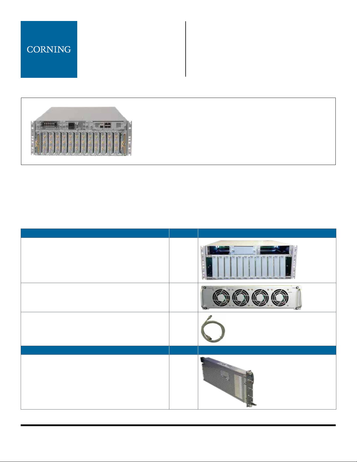
Headend Unit (HEU)
Quick Installation Sheet
CMA-267-AEN
GENERAL INFORMATION
1. The HEU chassis is supplied empty and only includes the factoryassembled fan module (FAM). All other modules are ordered separately
and must be installed.
2. Each HEU includes 14 slots — two for RF expander modules (RIXs) and
12 for extended radio interface modules (RIMes).
This document describes the installation procedure for the Corning® optical network evolution (ONE™) headend unit (HEU)
and relevant modules.
. REQUIRED KITS
The following items are required for installing the ONE™ HEU. If any of the listed items are missing, contact your
Corning representative.
HEU Kit Qty Item
Headend Unit Chassis (with blank panels on RIM and
one PSM slots) – includes factory-installed FAM in chassis
rear
FAM – single unit hosting four fans
(factory installed in chassis rear)
RJ45/RJ45 Communication Cable L = 2 m-2.15 m
(P/N 705900003) – HCM management cable
RIMe Kit (1-12 according to order) Qty Item
Extended Radio Interface Module (service specic) 1
1
1
1
Table 1. Kits Required for HEU Installation
Corning Optical Communications
Quick Installation Sheet | CMA-267-AEN | Page 1
Page 2
. REQUIRED KITS (CONTINUED)
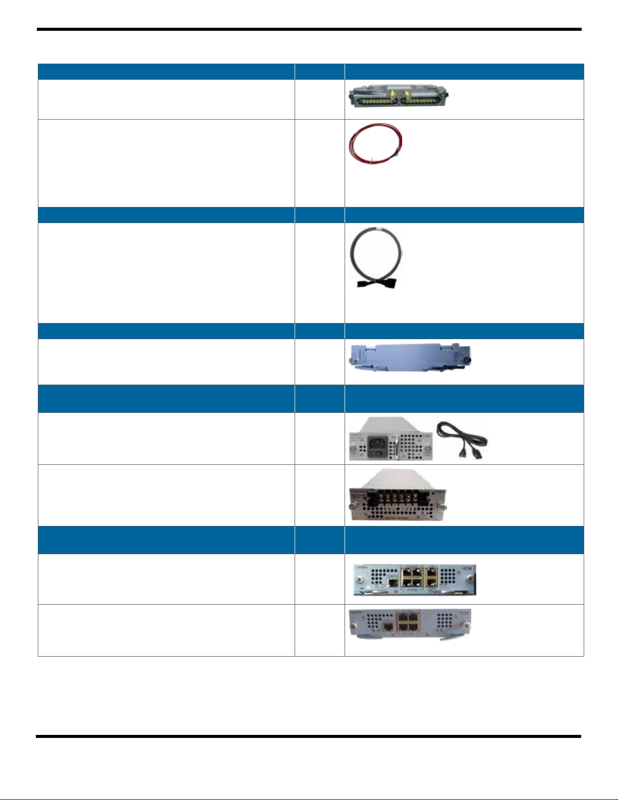
RIX Module Kit (1 or 2 according to order) Qty Item
Radio Expander Module – expands the RF sources to the
OIU
1
Pilot Transport Cable (P/N: PCKC47*) – Single QMA to
1
QMA cable; L = 47 in; used for passing reference clock
signal connections between RIX modules.
*Additional lengths can be ordered:
• PCKC20: L = 20 in
• PCKC63: L = 63 in
• PCKC79: L = 79 in
ERFC Cable Kit (according to order) Qty Item
ERFC (Expander Cable) - RF interface cable to HEU; 9-pin
1
SMP to SMP connector
Available in ve different lengths:
• ERFC16: L = 16 in
• ERFC24: L = 24 in
• ERFC34: L = 34 in
• ERFC40: L = 40 in
• ERFC59: L = 59 in
ETM Kit (according to order) Qty Item
ETM Expander Termination Module (for unused
1
Expander slot) unit
PSM Kit
Qty Item
(AC or DC modules — 1 or 2 kits according to order)
PSM-AC: 100-240 VAC Power Supply Module including
standard IEC 60320-1 C13 cable
1
(per
item)
PSM-DC: 48 V DC Power Supply Module; 9 A maximum;
Includes 6-pin terminal block connector
Controller Module Kit
(HCM or ACM — according to order)
HCM Kit (Headend Control Module) – installed in HEU;
enables local/remote management of the system units;
one HCM per system
ACM Kit (Auxiliary Control Module) – installed in
additional HEU/OIU/IHU chassis; provides management
connections between the unit and the HCM
Table 1. Kits Required for HEU Installation (continued)
Corning Optical Communications
1
Qty Item
1
1
Quick Installation Sheet | CMA-267-AEN | Page 2
Page 3
. MOUNT CHASSIS IN -IN RACK
Notes: • One HEU supports connections to up to four OIUs
• HEU chassis requires 4U rack height availability
• Rack nuts and screws not provided
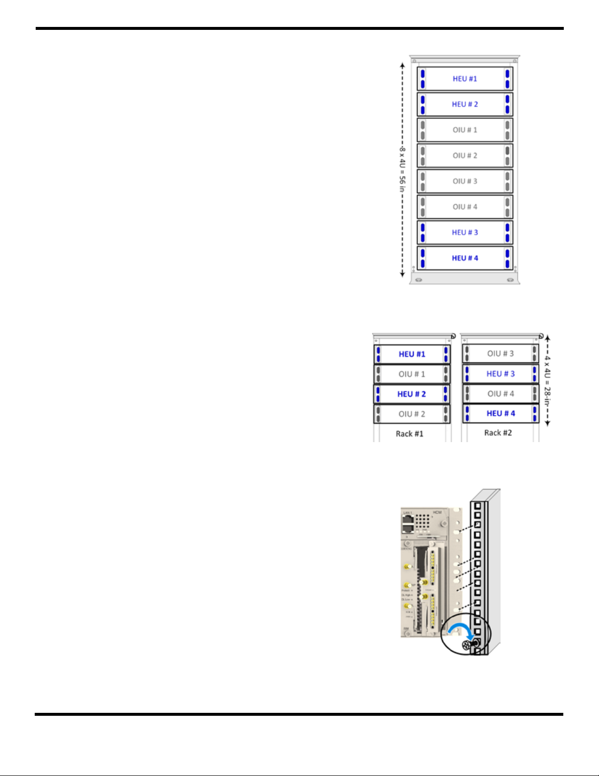
Step 1: Determine the location of the HEU in the rack
while considering additional HEU and OIU units
and the lengths of the available ERFC cable.
Figure 1 and Figure 2 describe the optimal rack
installations for a maximum 4x4 HEU-OIU
conguration in shared and dedicated equipment
scenarios.
Step 2: Referring to Figure 3, secure the units’ rack ears to
the rack frame as follows:
• Insert two screws halfway into the rack frame.
• Position the chassis on to the screws using the
handles and the top and bottom half slots of
the rack ears.
• Secure the unit in the rack via all applicable
bracket holes using the appropriate rack nuts
and screws.
Figure 1. 4x4 Installation Diagram – Dedicated
Corning Optical Communications
Figure 2. 4x4 Installation Diagram – Shared
Figure 3. Installing Chassis in Rack
Quick Installation Sheet | CMA-267-AEN | Page 3
Page 4
. INSTALL ALL MODULES
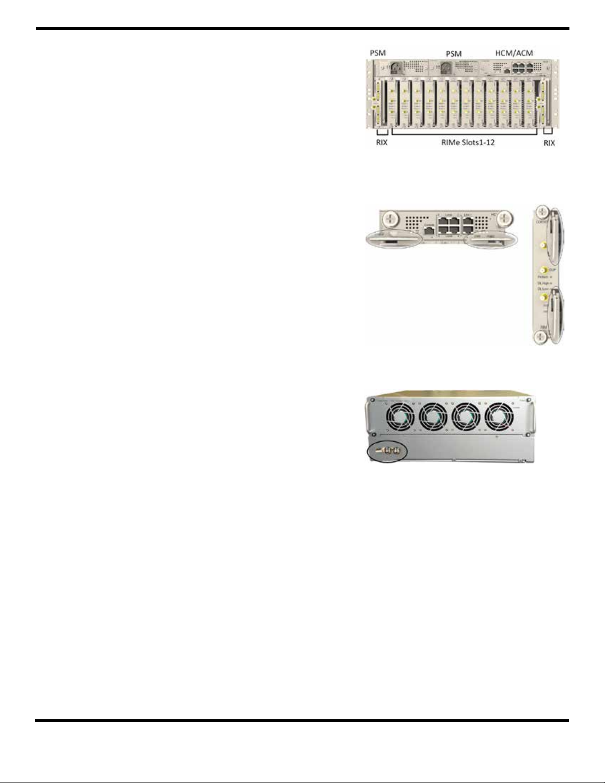
Note: For modules with ejectors (i.e., RIM, RIX, and
HCM/ACM) – verify that the ejectors are completely
open when inserting in dedicated slot and then
push in until the module clicks in to the backplane.
Figure 5 shows example of module type captive
screws and ejectors.
Step 1: Refer to Figure 4 for module locations. Remove
blank panel and slide in the relevant module
(chassis slots are 100 percent mistake proof):
• (One) HCM/ACM
• (One to two) PSM
• (Two) RIXs
• (One to 12) RIMs – no need to terminate
unoccupied RIM slot.
Step 2: Referring to Figure 5, secure the modules to the
backplane by:
• Closing the ejectors (for relevant modules)
• Tightening the captive screws
Figure 4. Example of Occupied HEU
Figure 5. Module Captive Screws and Ejectors
. GROUND HEU CHASSIS
The grounding connection is performed via a two-hole, standard
barrel grounding lug located on the HEU rear panel (see Figure 6).
Prise de terre du châssis HEU
La mise à la terre est réalisée en utilisant une cosse deux trous a
œillet standard, située à l’arriè du chassis HEU (voir Figure 6).
Required tools and components
The following additional (not supplied) tools and components
are required for connecting the system ground:
• Grounding wire — grounding wire should be sized according
to local and national installation requirements. The provided
grounding lug supports 14 AWG to 10 AWG stranded copper
(or 12 AWG to 10 AWG solid) wire conductors.
Note: The length of the grounding wire depends on the proximity
of the switch to proper grounding facilities.
• Phillips-head screwdriver
• Crimping tool — for crimping the grounding wire to the lug.
• Wire-stripping tool — for removing insulation from
grounding wire
Figure 6. Grounding Lug (Chassis Rear)
Corning Optical Communications
Quick Installation Sheet | CMA-267-AEN | Page 4
Page 5
. CONNECT RIMS TO RF SOURCE(S)
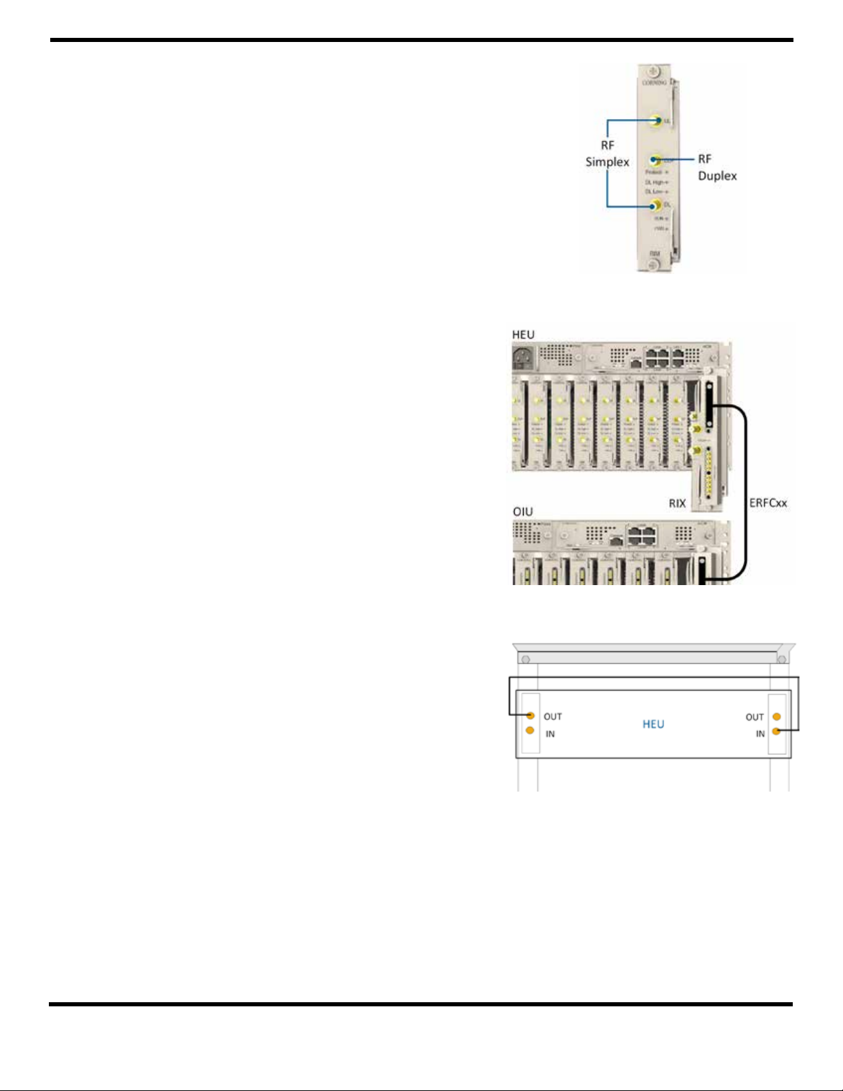
For each RIMe — connect the external RF source to the
corresponding RIMe (service specic) simplex or duplex
QMA connectors. See Figure 7.
. RIX TO OIX CONNECTIONS
Note: Each RIX module can be connected to two OIUs.
Using the appropriate length ERFC cable (according to distance
of available OIX port), connect the HEU RIX module 9-Pin
connector to the corresponding connector on the OIU OIX
module. See Figure 8.
Refer to Section 11 for schematic diagram of coax connections
in a maximum HEU-OIU conguration of 4x4 where all HEU
units are connected to all OIU units.
. RIX PILOT CLOCK CONNECTIONS
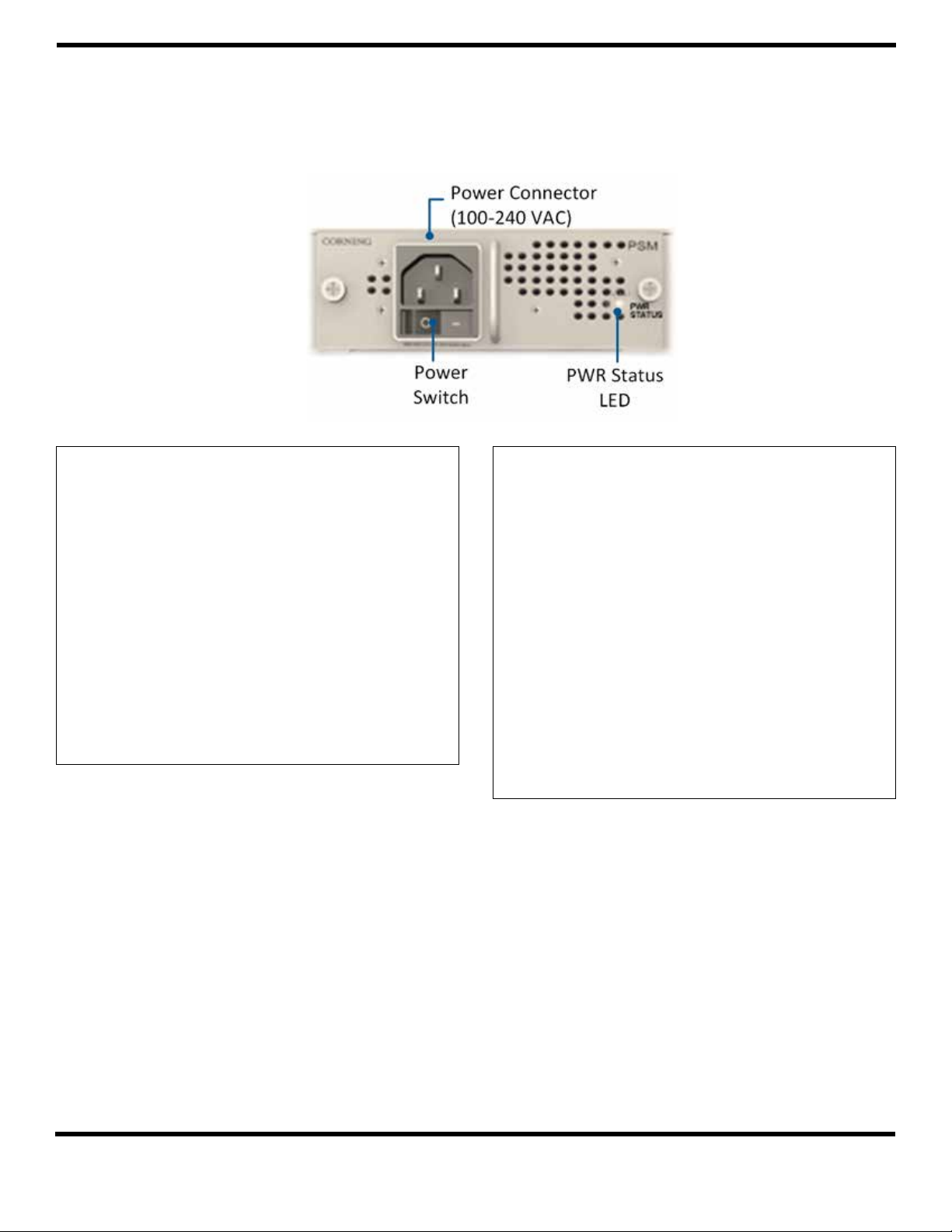
The pilot clock connections are required in both single- and
multiple-chassis congurations. Referring to Figures 9, 10, and
11, use the QMA/QMA jumper cable (PCKC47 provided with
each RIX) to connect the REF OUT and REF IN ports of each of
the RIXs in the HEU chassis.
Figure 7. RIM RF Source Interfaces
Notes: • The REF IN and REF OUT pilot clock ports must be
connected in a closed loop as shown in Figure 10.
• Both RIX modules of each chassis must be
connected.
Figure 8. HEU to OIU Coax Connections
Figure 9. Pilot Clock Connections Example –
Single HEU with Two RIXs
Corning Optical Communications
Quick Installation Sheet | CMA-267-AEN | Page 5
Page 6
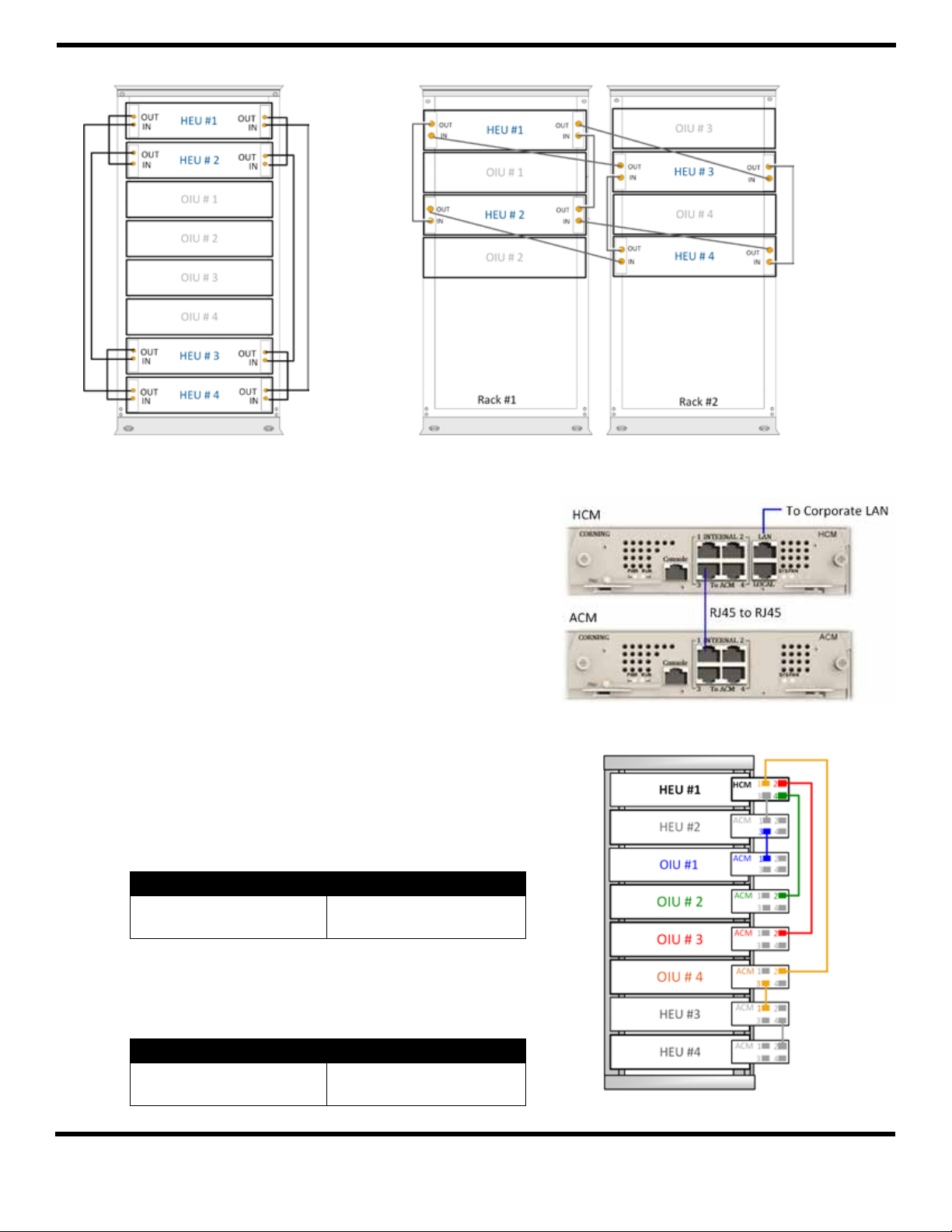
Figure 10. Pilot Clock Connections Diagram –
(4x4) Shared Rack
Figure 11. Pilot Clock Connections Diagram –
(4x4) Dedicated Rack
. MANAGEMENT CONNECTIONS
Notes: • One RJ45/RJ45 management cable
is provided with each headend unit
(i.e., HEU/OIU).
• Management connections are also described
in HCM quick installation sheet.
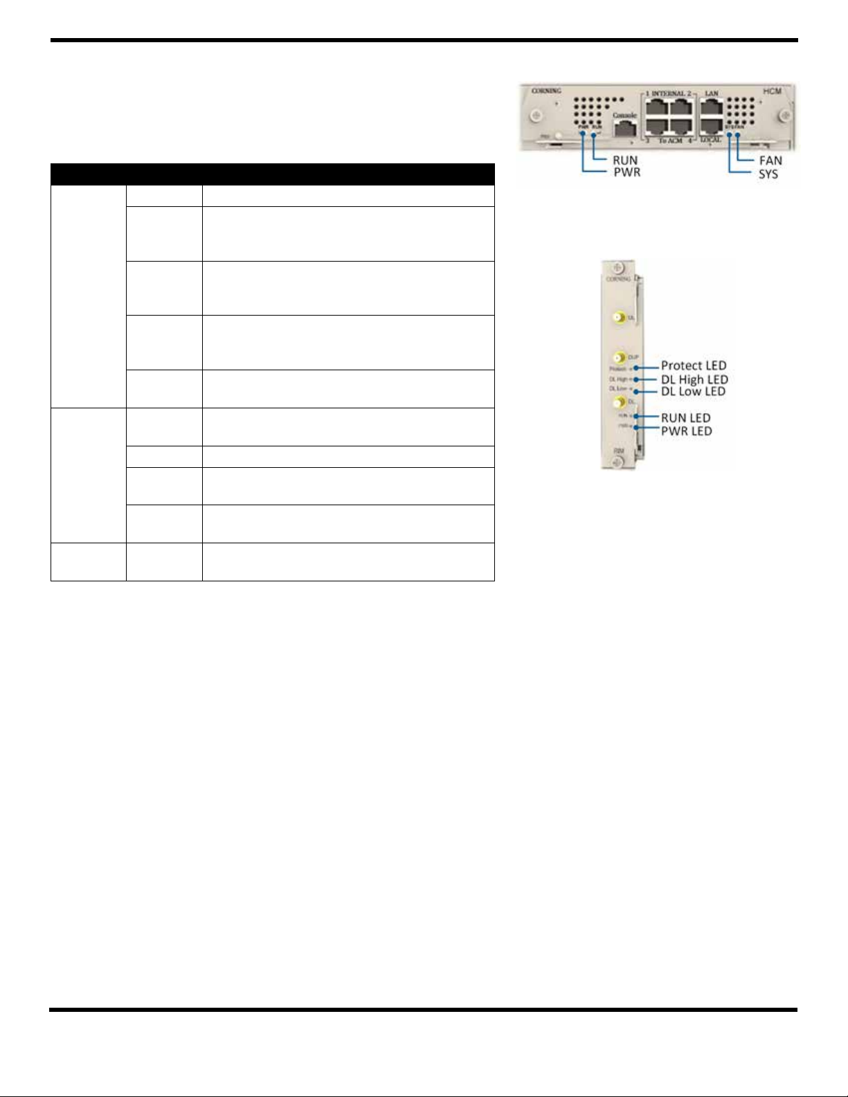
For HCM only — using the provided RJ45/RJ45
communication cable, connect the HCM LAN port to the
corporate LAN ( Figure 12).
HCM to ACM Management Connections — using RJ45/RJ45
communication cables perform the headend management
connections as follows:
• Referring to Figure 12 — for congurations with one
HCM and up to four ACM modules (e.g., one HEU and
four OIUs), directly connect as follows:
From (any) HCM …. To (any) ACM…
INTERNAL (TO ACM)
Port 1/2/3/4
INTERNAL (TO HCM)
Port 1/2/3/4
Figure 12. HCM-to-ACM Connection
• Referring to Figure 13 — for congurations with one
HCM and more than four ACMs (e.g., 4x4 HEU-OIU
congurations) where there are only four available HCM
INTERNAL ports:
From (any) ACM …. To any ….
INTERNAL (TO ACM)
Port 1/2/3/4
Corning Optical Communications
Other available ACM
“INTERNAL (TO ACM)” port
Figure 13. 4x4 Management Connections (Example)
Quick Installation Sheet | CMA-267-AEN | Page 6
Page 7
. POWER UP
Note: Only AC power connections are described in this document. Refer to PSM-DC quick
installation sheet (CMA-365-AEN) provided with PSM-DC for wiring pinout.
Figure 14. AC Power
Supply Module LEDs
ATTENTION!
• Approved power cable – the entire length of the
power cable (or exible cord) and the insulation must
be intact. The cable must be rmly connected to both
the electrical plug and the unit itself.
• Standard plug – the use of a standard plug is
mandatory. The use of a nonstandard power plug can
cause electrocution! Also, plugging a nonstandard
plug into a standard socket that does not correspond
to the plugs’ shape can damage the socket making it
a safety hazard.
• Always disconnect all AC power sources from the unit
before servicing (i.e., maintenance).
To power up the unit:
Connect PSM-AC power connector to the AC power
source using the provided AC power cable and turn
power switch on. See Figure 14 for AC connector location.
• Power input: 100-240 VAC
• Power consumption (fully loaded chassis):
200 W (maximum); 12 W per RIMe
ATTENTION!
• Câble d’alimentation qui est approuvé —la totalité
de la longueur du câble d’alimentation (ou cordon
souple) et de l’isolation doit être intact. Le câble doit
être bien connecté à la fois à la prise électrique et
l’appareil.
• Prise électrique standard — l’utilisation d’une
che standard est obligatoire. L’utilisation d’un
cordon d’alimentation non standard peut entraîner
l’électrocution! De meme, brancher une che nonstandard sur une prise standard ne correspondant
pas à la forme de de la che, peut endommager la
Prise, ce qui en fait un danger de sécurité.
• Débrancher toujours toutes les sources
d’alimentation CA de l’unité avant l’entretien.
Pour mettre l’unité sous tension:
Branchez la prise d’alimentation du PSM-AC à la source
d’alimentation secteur à l’aide du câble d’alimentation
secteur fourni et allumer l’interrupteur. Voir Figure 14
pour l’emplacement du connecteur AC.
• Alimentation: 100-240 VAC
Corning Optical Communications
• Consommation maximale électrique
(pour les châssis entièrement charges):
200 W ; 12 W pour RIMe
Quick Installation Sheet | CMA-267-AEN | Page 7
Page 8
. VERIFY NORMAL OPERATION
If RF source is operational, verify that the RIM (see Figure 7)
and HCM/ACM (see Figure 15) LEDs indicate normal operation:
Module LED Description
RIMe Protect N/A
DL High Off – DL RF input level in threshold range
Steady Red – DL RF input level is 3 dB above
maximum expected power
DL Low Off – DL RF input level in threshold range
Steady Red – DL RF input level is 15 dB below
maximum expected power
RUN Blinking green – RIMe software has initialized
and is up and running
Off – Power off
PWR Steady green – input power is within required
range
HCM/ACM PWR Steady green – power input detected by
HCM/ACM
RUN Blinking green – HCM software up and running
SYS Steady green – overall status of the managed
system is ok
FAN Steady green – normal operation status for
all fans
PSM PWR
Table 2. RIMe, HCM/ACM, and PSM LED Descriptions
STATUS
On – power input detected
Off – no power
Figure 15. HCM/ACM LEDs
Figure 16. RIMe LEDs
Corning Optical Communications
Quick Installation Sheet | CMA-267-AEN | Page 8
Page 9
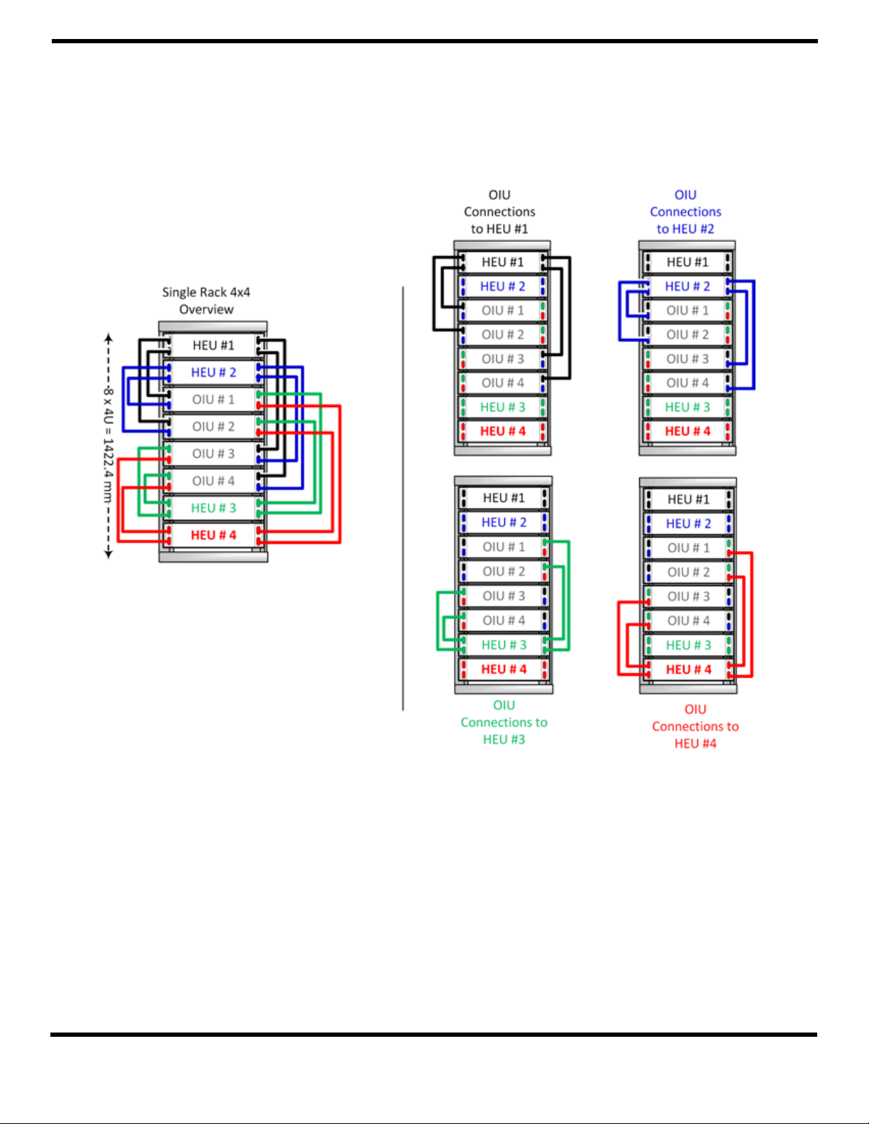
. COAX CONNECTIONS FOR HEU-OIU X INSTALLATION CONFIGURATIONS
Figure 17 and Figure 18 illustrate the optimal installation congurations when installing four HEU and four
OIU chassis in a rack so that all HEUs can be connected to all OIUs. The optimal conguration takes into
consideration the minimum and maximum ERFC cable lengths (provided with OIXs) in either a single
19-inch rack (shared rack equipment scenario) or two separate racks (dedicated rack per operator).
Figure 17. HEU-OIU 4x4 Installation Conguration for Shared Provider Equipment
Figure 17 illustrates how each HEU is connected to each OIU in a dedicated equipment (single rack) scenario. In
Figure 17, the port numbers (1-4) indicated on each HEU correspond to the OIUs in the rack and vice versa for the
OIU port numbers. For example, Port 3 in HEU #1 indicates the connection to OIU #3, whereas Port 1 in OIU #3
indicates the connection to HEU #1.
Corning Optical Communications
Quick Installation Sheet | CMA-267-AEN | Page 9
Page 10
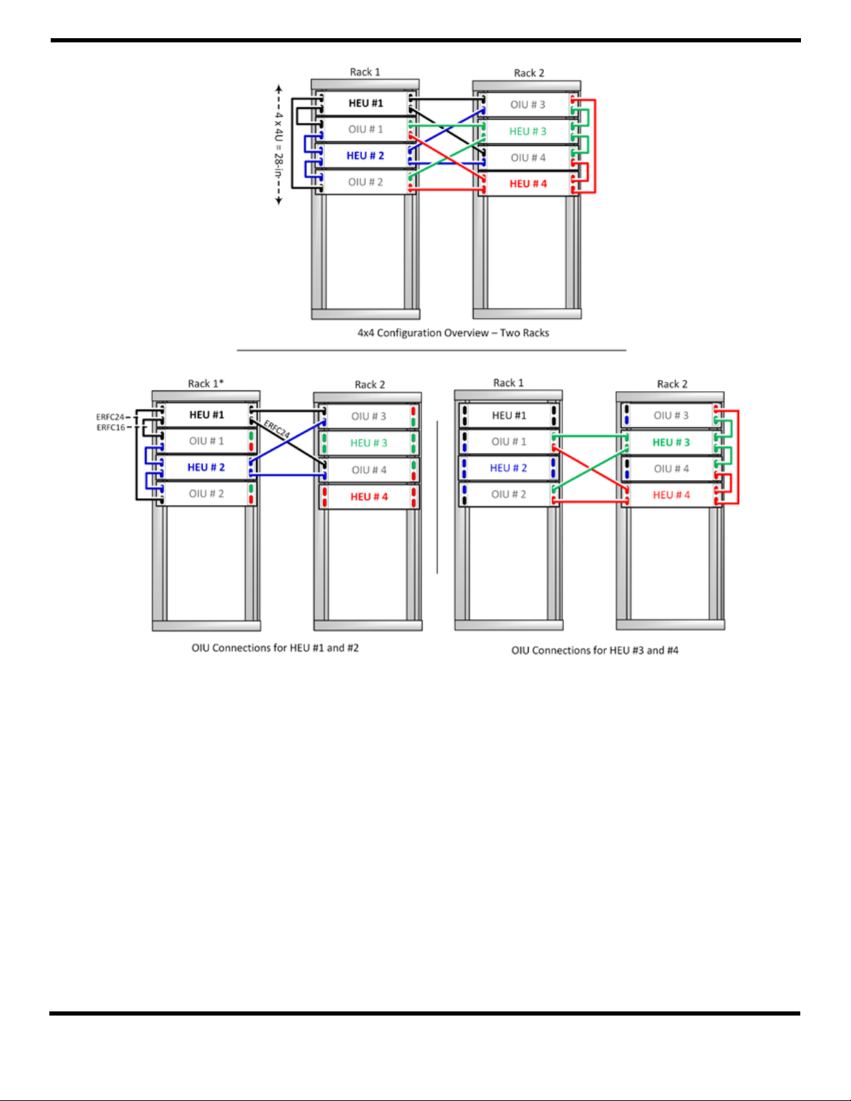
*The ERFC cables indicated in Rack 1 are provided as an example of the lengths required for this rack conguration.
Figure 18. HEU-OIU 4x4 Installation Conguration for Dedicated Provider Equipment
Figure 18 illustrates how each HEU is connected to each OIU in a shared equipment (dual rack) scenario. In
Figure 18, the port numbers (1-4), indicated on each HEU, correspond to the OIUs in the racks and vice versa
for the OIU port numbers. For example, Port 3 in HEU #1 indicates the connection to OIU #3, whereas Port 1
in OIU #3 indicates the connection to HEU #1.
Corning Optical Communications
Quick Installation Sheet | CMA-267-AEN | Page 10
Page 11

NOTES:
Corning Optical Communications
Quick Installation Sheet | CMA-267-AEN | Page 11
Page 12

NOTES:
Corning Optical Communications LLC • PO Box 489 • Hickory, NC 28603-0489 USA
800-743-2675 • FAX: 828-325-5060 • International: +1-828-901-5000 • www.corning.com/opcomm
Corning Optical Communications reserves the right to improve, enhance, and modify the features and specifications of Corning Optical Communications products without prior notification. A complete listing of
the trademarks of Corning Optical Communications is available at www.corning.com/opcomm/trademarks. All other trademarks are the properties of their respective owners. Corning Optical Communications is
ISO 9001 certified. © 2015, 2018 Corning Optical Communications. All rights reserved. CMA-267-AEN / April 2018
P/N 709C012102 Rev. A00
 Loading...