

Page 1
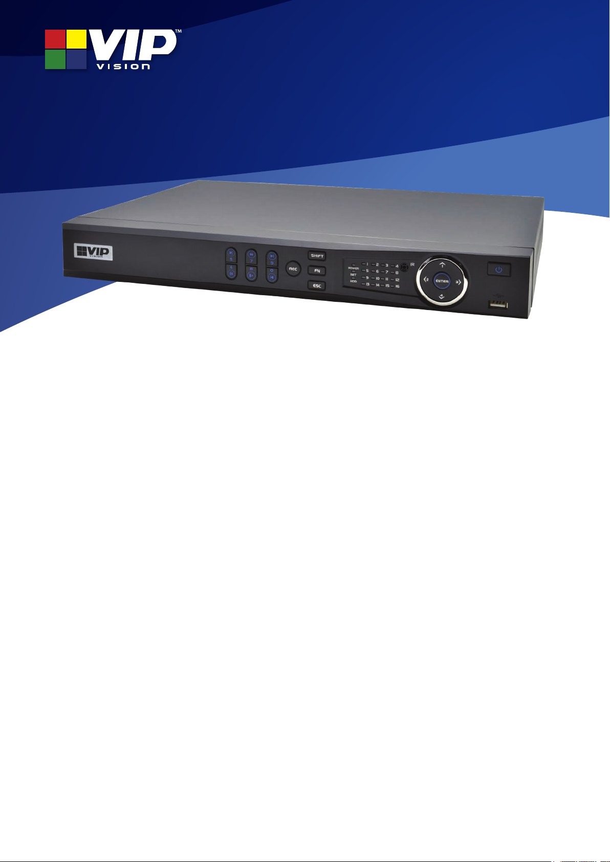
Models: NVRPRO Series
VIP Vision™ Network Video Recorder
Quick Start Guide
Thank you for purchasing a VIP Vision Network Video Recorder
This Quick Start Guide covers basic setup, installation and use of your surveillance system.
For the full user manual, instructional videos, tips on using your surveillance system &
warranty information, please visit: www.vip-vision.com
Version: VIPNVR-Q119.1
Page 2

1. Pre-Installation
1.1 Pre-Installation Safety Information
Before connecting your NVR (network video recorder) or cameras, please ensure the following safe installation
guidelines are adhered to.
• Do not place cords from the NVR where they can be pinched or stepped on.
• Do not place heavy objects on cords, or cover cords with rugs or carpet.
• Do not expose the NVR to excessive heat or moisture.
• Leave at least 50mm of space between the NVR and other objects to allow ample air circulation.
• Never immerse any component in water and do not spray cleaners or solvents on the cameras.
• Shut down and unplug the recorder before cleaning. When cleaning, use a damp, lint-free cloth only.
• Service of your NVR or surveillance cameras should only be handled by qualied technicians.
1.2 Connecting your NVR and Cameras
The following section will detail connecting the NVR and surveillance cameras. It is recommended that cameras and
connections are tested before mounting. If there is no image, an error message or dark screen when rst connecting
cameras, see the Troubleshooting in Section 6 in this guide.
Refer to 1.3 NVR Rear Panel & Setup Diagram for full NVR & system diagrams.
1. Connect the cameras to the NVR: Using CAT5e/CAT6 LAN cables, connect to the network port of the NVR.
2. Connect camera power: Cameras are powered by CAT5e/CAT6 LAN cable. No external power supply is needed.
3. Connect a display: Using an HDMI or VGA cable, connect a monitor or television (not included).
4. Connect the mouse: Connect the USB mouse to the rear USB port, saving the front port for easy USB backup.
5. Connect to your local network: Using the included Ethernet patch cable, connect to your switch or router.
6. Connect NVR power: Plug in the supplied AC power cord to the rear of the NVR.
Upon activating power, LED lights at the front of the NVR should turn on and the NVR will sound on startup. The
NVR will then run your surveillance user interface. Cameras and LAN / Internet will be detected automatically. This
completes a successful rst boot of your surveillance system and you may begin conguring surveillance cameras.
2
VIP Vision NVR Quick Start Guide - Version: VIPNVR-Q119
Page 3
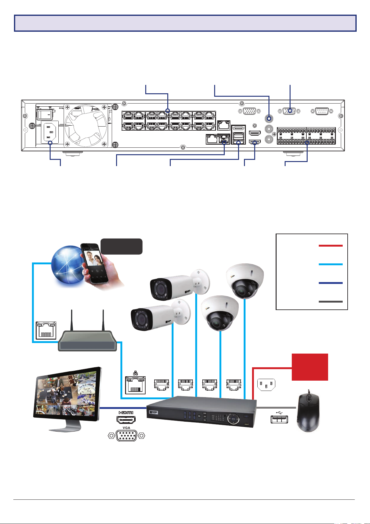
1.3 NVR Rear Panel & Setup Diagram
NOTE: Your NVR (network video recorder) model may differ - the 16 channel NVR (NVR16PRO7) is referenced below.
100~240VAC:
Power input
Video Inputs: PoE/ePoE
network ports for camera
data & power
LAN: Network
(Ethernet) Port
Remote View
via Mobile
Audio: 1x channel RCA
input/2x channel output for
microphone/loudspeaker
USB: Connect
mouse or
backup device
Fig. 1.1: NVR Rear Panel Diagram
HDMI: HDMI video
output for modern
monitors & TVs
VGA: Video
output for older
monitors
Alarm: External
alarm trigger
input/output
Power Cable
Internet Connection
Router
Monitor
IP Cameras
Network (PoE)
HDMI/VGA
NVR Mouse
USB
100-240VAC
Mains
Visit www.vip-vision.com for full user manual and support
Fig. 1.2: System Setup Diagram
3
Page 4
2. NVR and Camera Conguration
2.1 First Boot and Startup Wizard
After successful connection and boot of your NVR, you will be taken through rst-time setup for your surveillance
system. Here you will congure system security and begin customising your NVR, including setting camera encoding
options, record scheduling, network setup and remote view conguration. A physical keyboard is not required or
supported; an on-screen keyboard will appear when required.
NOTE: Each setting shown in the Startup Wizard can be modied later via the NVR Main Menu. See the Menu Quick
Guide in Section 6 or see the full user manual for more information.
Following the prompts, complete each section in the Startup Wizard, as detailed below:
NOTE: Screenshots have been edited for legibility in print.
2.1.1 Startup Wizard
When the NVR is powered up for the rst time or the NVR is restored to factory settings, the Startup Wizard will be
displayed. Users can set common NVR functions by following the procedures step-by-step
2.1.2 Securing your NVR
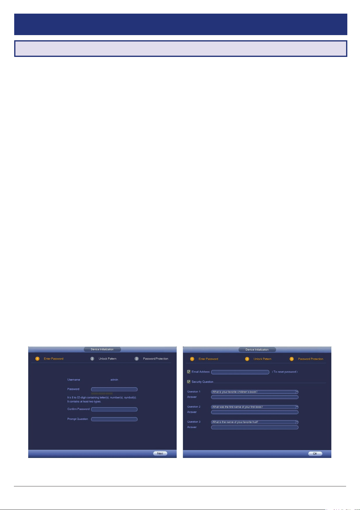
In the Startup Wizard, you will be prompted to change the admin user password. This is to prevent unauthorised
remote access via the Internet to your NVR.
1. Enter a strong admin user password, using letters, numbers & symbols. Conrm this password.
2. (Recommended) Enter a Prompt Question (password hint).
3. (Optional) Draw an Unlock Pattern for quick unlocking.
4. (Recommended) Enter an email address to be used for password resets.
5. (Recommended) Enter security questions/answers to be used if the admin password is forgotten. Note that answers
are case-sensitive.
NOTE: Email address password resets require a mobile phone with the DMSS app & internet access.
NOTE: We strongly recommend setting up email password reset and security questions. If the password is forgotten
and no recovery method is set up, the recorder will need to be sent back to VIP Vision for a system reset, which will
incur a fee even if the system is still within the warranty period.
Fig. 2.2: Enter Password screen. Fig. 2.3: Password Protection screen.
4
VIP Vision NVR Quick Start Guide - Version: VIPNVR-Q119
Page 5
2.1 First Boot and Startup Wizard (continued)
2.1.3 Automatic Updates
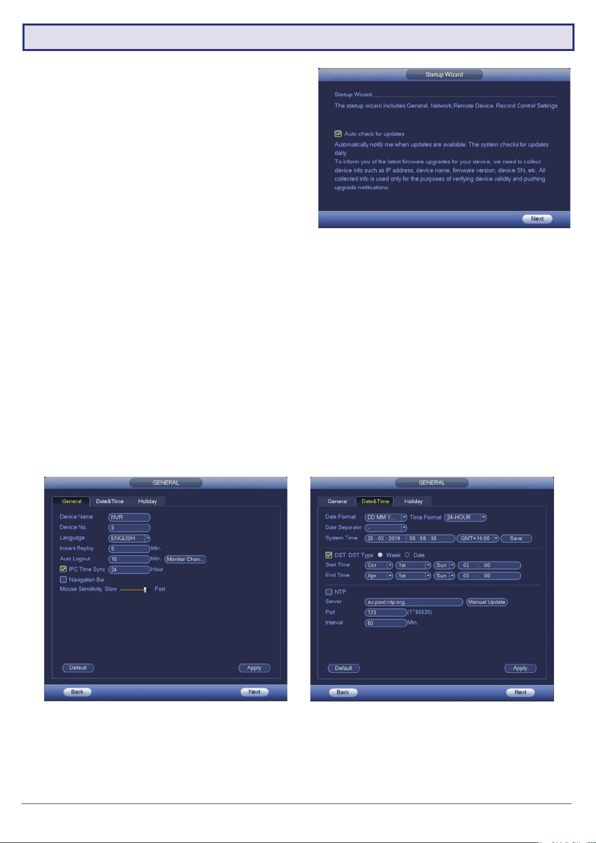
Here, you can choose whether you want your system
to Auto-check for updates. This feature will notify
you whenever a new rmware update is available and
downloads it from VIP Vision.
For compatibility with future cameras and to receive
security updates, we recommend automatic updates be
turned on.
NOTE: Automatic updates require an internet connection.
Fig. 2.4: Auto-check for updates
2.1.4 General NVR Setup
You will now be directed to General setup. Here you can conrm basic options of your NVR. By default, your NVR is
set have 5 minutes instant playback and logout automatically after 10 minutes. You can also change mouse sensitivity
and conrm date & time.
Default settings are adequate to get started, we recommend checking the following:
1. In the General menu, assign a name to your NVR by changing the Device Name eld.
2. Click Next to go to the Date & Time menu and conrm correct settings. This directly affects recording, footage
search & playback. You can optionally enable NTP to ensure a correct time (this requires an internet connection).
3. Users in NSW, VIC, SA, TAS and ACT will need to enable DST (Daylight Saving Time). Adjust Start Time & End
Time settings according to your region and the year.
NOTE: Daylight Saving Time begins at 2am on the rst Sunday in October, when clocks are put forward one hour. It
ends at 2am (which is 3am Daylight Saving Time) on the rst Sunday in April, when clocks are put back one hour.
Fig. 2.5: General setup section Fig. 2.6: Date & Time setup
Visit www.vip-vision.com for full user manual and support
5
Page 6
2.1 First Boot and Startup Wizard (continued)
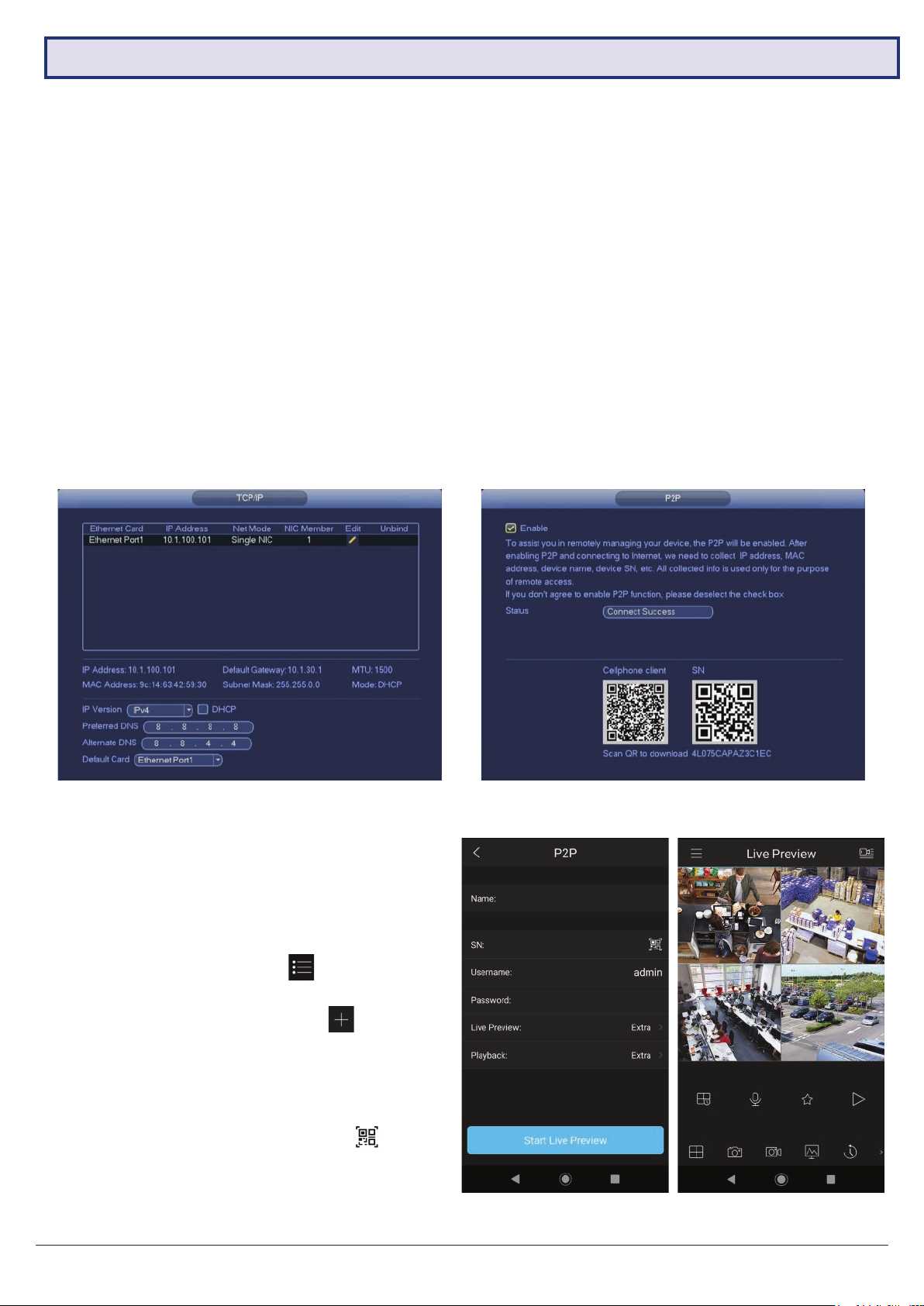
2.1.5 Conguring TCP/IP, P2P, and Remote View
NOTE: For the following section, please ensure the LAN (Local Area Network) is connected to your router or switch
and that your Internet connection is available. Also, have your Internet connected phone or tablet ready for conguring
surveillance remote view.
Network setup will be prompted next, enabling you to connect your NVR to the Internet. First ensure that your NVR
is connected to your switch or router via the included CAT5 cable (detailed in Section 1.3). For the simplest setup we
recommend using DHCP to connect to the Internet. You will then be prompted to congure P2P for remote view on
your device.
1. In the TCP/IP section, see Fig. 2.7. The IP address
of the NVR will be shown.
2. Select IPv4 and DHCP (Dynamic Host Conguration
Protocol).
3. Should you wish to use a static address, contact
your Internet administrator for details.
4. Click Next to continue.
5. Click Enable to enable P2P remote view.
6. NVR Status should read Online. This indicates an
active Internet connection. (This may take a few
minutes).
7. Scan the left QR code, Cell Phone Client, or search
your App Store to download the iDMSS/gDMSS or
the EasyviewerLite app.
Fig. 2.7: TCP/IP setup section settings (example only) Fig. 2.8: P2P setup section, with QR codes (example only)
The following details conguring remote view via the
iDMSS (Apple iOS) or gDMSS (Android) on your
device. Depending on the device, menus may function
or appear slightly different to those explained below.
1. Select the Camera button on the app home screen.
2. Open the application menu and select the
Device Manager tab
3. To add your NVR, select add device
4. In the Add Device menu, select Wired Device, then
select P2P.
5. Name your NVR and enter your admin password.
6. In the SN eld, select the QR code icon
7. Scan the Device SN QR code (shown in Fig. 2.9).
The SN will be auto-lled if the scan is successful.
8. Select Start Live Preview to view your cameras.
.
.
.
Fig. 2.9: Add Device menu and Live Preview for Android
6
VIP Vision NVR Quick Start Guide - Version: VIPNVR-Q119
Page 7
2.1 First Boot and Startup Wizard (continued)
2.1.6 Conguring Surveillance Cameras
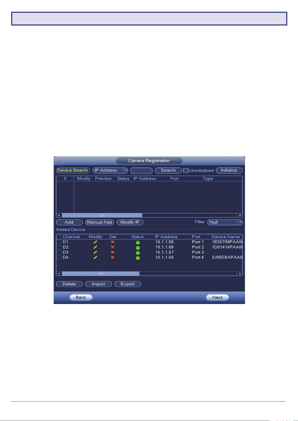
After conguring remote view, the Startup Wizard will take you to the Camera Registration menu. This menu will display
all detected cameras. Users can also add camera manually.
Device search: Search all network cameras in the same network segment. To add a camera, double click on the
camera list or check the box then click Add button. To add camera manually with known IP address, you can:
1. Type the camera’s IP address in the box left of the Search button, then click Search.
or
2. Click the Manual Add button and input the camera’s IP address and password.
Channel: This is the camera’s channel number.
Status: The connection status of the camera. A red circle indicates the camera is ofine. A green circle indicates the
camera is online.
IP Address: The IP address of the network camera.
Port: The port number of the network camera.
Visit www.vip-vision.com for full user manual and support
Fig. 2.10: Camera Registration
7
Page 8
2.1 First Boot and Startup Wizard (continued)
2.1.7 Conguring Recording Schedules
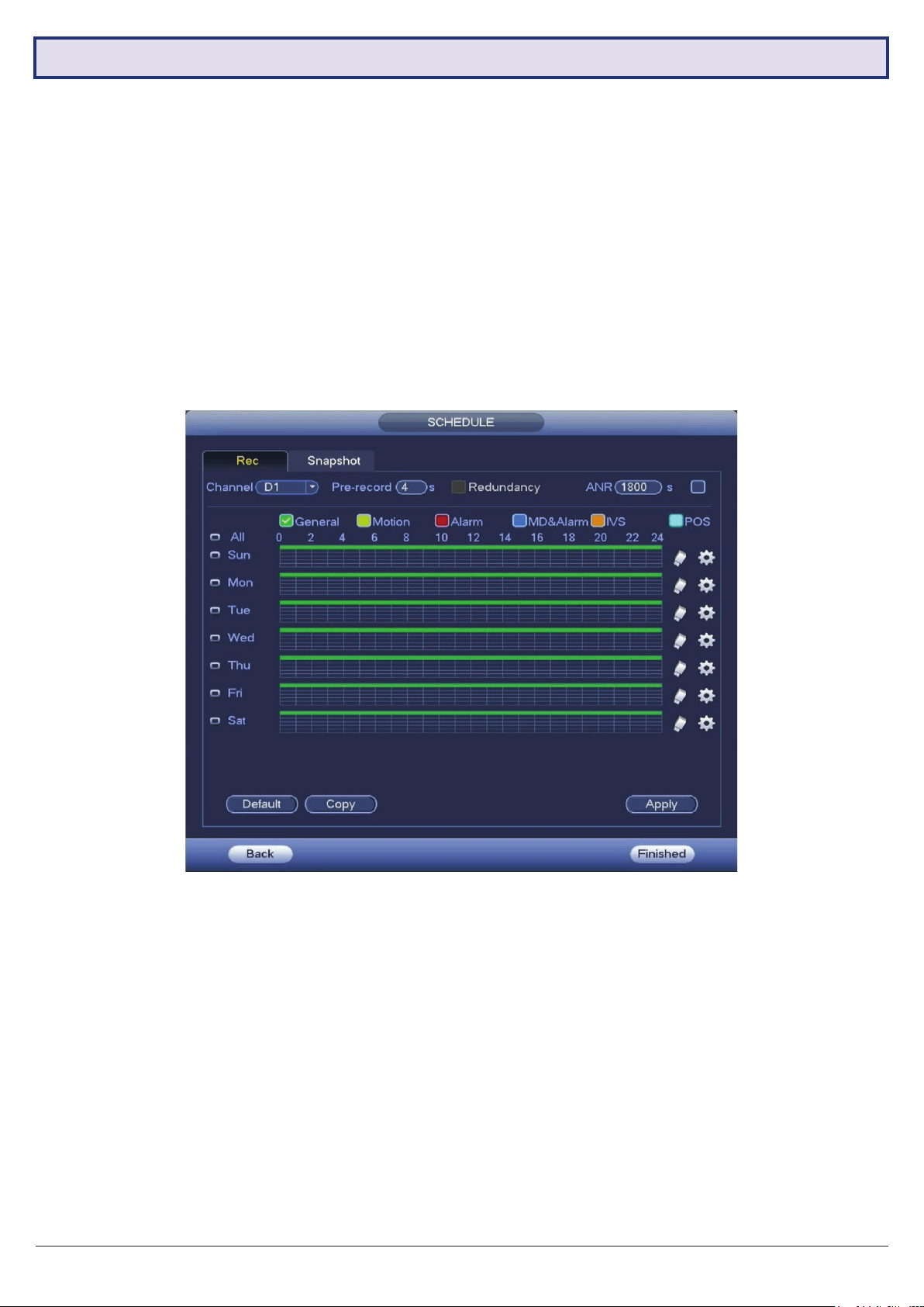
Finally, you will be prompted to setup your Schedule for recording. Here you can dene the recorded footage schedule
in the Record menu (Fig. 2.11), and the recorded image snapshot schedule in the Snapshot menu. By default, cameras
are set to non-stop Regular recording (24 hours a day, 7 days a week).
Schedules can be set in hourly periods for individual days for each camera, with colour-coded options for:
• General (green) for all regular recording.
• MD (yellow) for recording on motion detection.
• Alarm (red) for recording on triggering an integrated alarm.
• MD & Alarm (blue) for simultaneous alarm/motion detection recording.
• IVS (orange) for recording on triggering IVS (Intelligent Video Surveillance) such as a virtual tripwire.
• POS (light blue) for point of sale transactions.
We recommend adding motion detection and intelligent recording to all channels to accompany your regular recording:
Fig. 2.11: Recording Schedule
Setting Motion Detection & Intelligent Recording
1. Click the Channel drop down to select All cameras.
2. In the days column, toggle the All check box to simultaneously set recording schedule parameters for every day of
the week.
3. Check the blue MD check box to select motion detection recording.
4. Click the schedule to ll in areas for motion detection recording. We recommend a 24/7 schedule to mirror the
Regular recording schedule (Fig. 2.10).
5. Repeat steps 3 & 4 with the orange IVS check box to set intelligent recording (tripwire, face detection, etc).
6. Click OK to the conrm recording schedule changes and move on to Snapshot Schedule.
8
VIP Vision NVR Quick Start Guide - Version: VIPNVR-Q119
Page 9
2.1 First Boot and Startup Wizard (continued)
Setting Snapshot Schedule
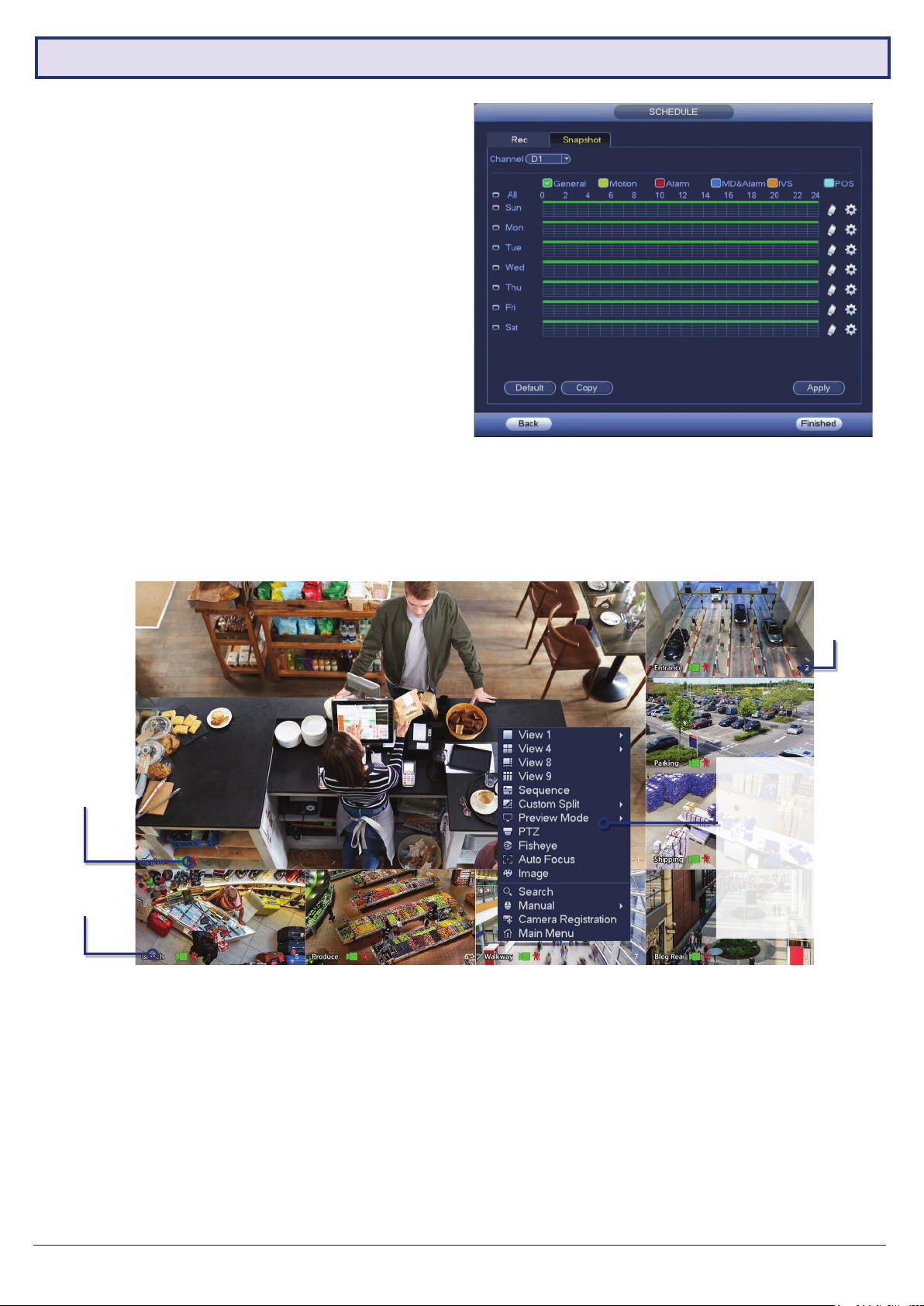
The Snapshot Storage Schedule is congured similarly
to the Recording Schedule. For consistency between
recording and snapshots, we recommend using the same
settings used for the Recording Schedule.
You have now set up motion detection & intelligent
recording. This will be benecial when it comes to
searching footage in playback (Section 4.0). This can be
edited any time from Main Menu -> Storage -> Schedule.
2.1.8 Completed Setup
Fig. 2.12: Snapshot Schedule
Startup setup is complete. Below is an example of a View 8 Liveview setup. Before mounting cameras, familiarise
yourself with the user interface and menu layout.
Camera
Number
Camera
Status Icons
Camera Name
Right-click Menu:
• Main Menu
• Search Playback
• PTZ/Focus Control
• Viewing Options
• Search Playback
• Manual Record
• Preview Mode
• Colour Control
• Image Snapshot
Fig. 2.13: View 8 Liveview screen with right-click menu open.
Liveview Controls
• Double-click on a camera window to make it full-screen; double-click again to return to normal view.
• Right-click to access the right-click menu.
• From the right-click menu, click Main Menu to access most conguration settings.
Main Menu Controls
• Mouse wheel scroll to view more menu options.
• Left-click to enter a menu.
• Right-click to return to the Main Menu / return to the Liveview screen from the Main Menu.
Visit www.vip-vision.com for full user manual and support
9
Page 10
2.2 Conguring Surveillance Cameras
2.2.1 Camera Quality & Bit Rate
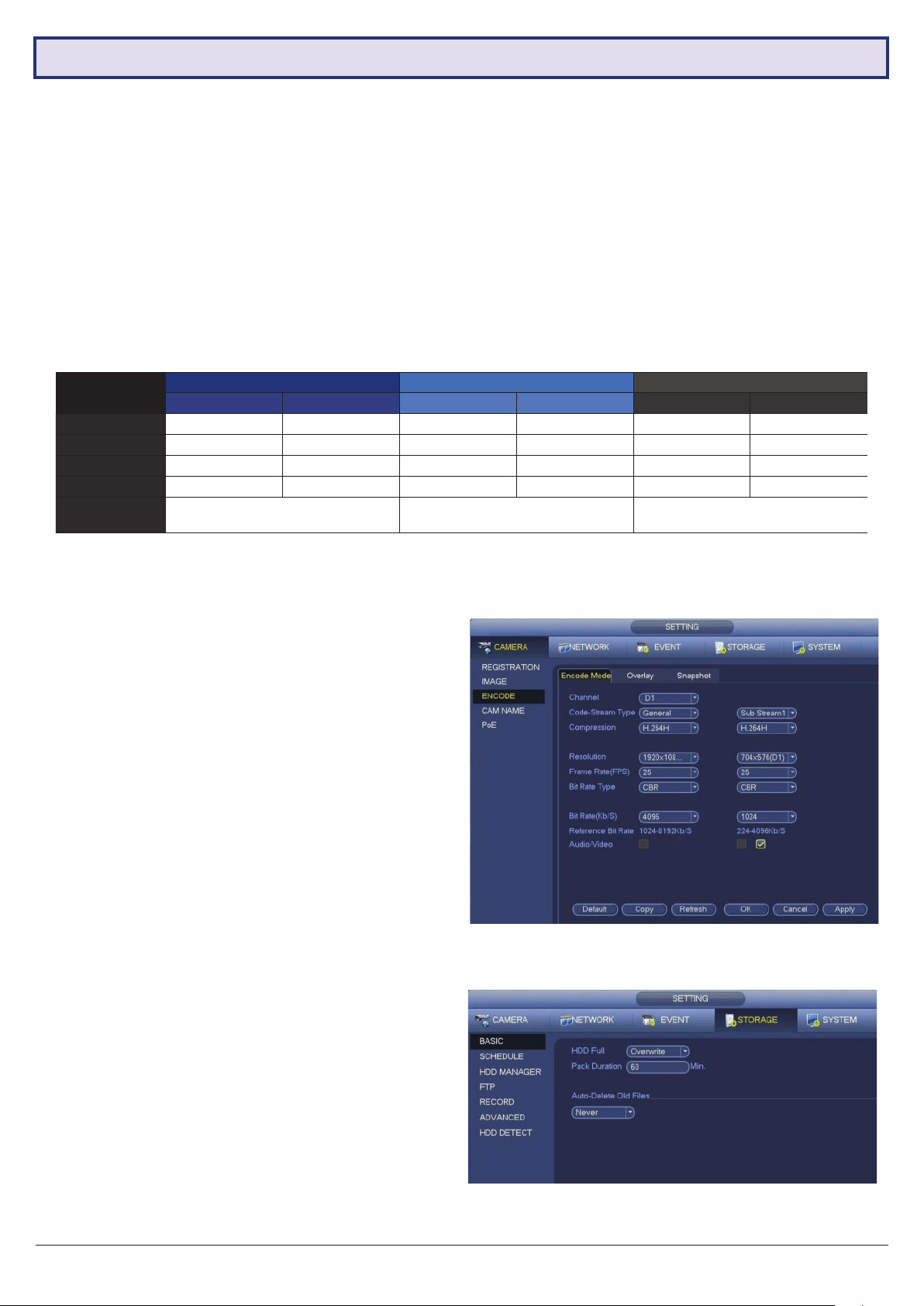
After the Startup Wizard has been completed. You can congure the camera via the Encode menu. This section
determines the overall quality of footage recorded by your NVR. These can be adjusted to optimise for video quality or
recording time, depending on your preference.
Each camera features a Main Stream for high quality streaming to the NVR; and a Sub Stream for low quality, low data
streaming to your remote view phone or tablet. You can congure both of these streams for each individual camera,
so you can choose to prioritise quality for important cameras and recording time for others.
Fig. 2.21 details Default Values, Quality Optimised values and Max. Recording-time optimised values for a 2T HDD.
NOTE: Total record times below are estimates based on a 2.0MP system. Actual total record time will differ.
Field
Resolution
Frame Rate
Bit Rate Type
Bit Rate
Approx. Total
Record Time
Main Stream Sub Stream Main Stream Sub Stream Main Stream Sub Stream
1920 * 1080 352 * 288 1920 * 1080 704 * 576 1920 * 1080 352 * 288
Default Values Quality Optimised Recording Time Optimised
15fps 15fps 15fps 15fps 10fps 10fps
CBR CBR CBR CBR VBR VBR
2048Kb/s 320Kb/s 4096KB/s 640KB/s 2048Kb/s 320Kb/s
8+ Days 4+ Days 14+ Days
Fig. 2.14: Suggested camera stream values to be set for individual cameras
NOTE: To conserve mobile data usage while using remote view, 320Kb/s Bit Rate is recommended for Sub Streams.
Encode Menu
• In the Encode menu, select each camera channel
and set the desired encoding options based on table
above (Fig. 2.14).
Snapshot Menu
•
In the Snapshot menu, you can congure the NVR
to
record image snapshots to be taken at Timing
intervals, based on the Snapshot Recording Schedule
(see Section 2.17), or on Trigger, via camera motion
detection.
• This creates image les alongside your recorded
footage.
2.1.7 Conguring Basic Storage Settings
Here, you can congure the settings for situations when
the HDD is full, le size/time length of recorded video, and
the settings for auto-deleting old les.
• HDD Full: Congure the settings for when all the read/
write discs are full, and there is no more free disc.
• Pack Mode: Congure the time length and le length
for each recorded video.
• Auto-Delete Old Files: Congure whether to delete
the old les or not. If yes, also determines how many
days of footage are deleted.
10
Fig. 2.15: Encode setup section channel 1 settings example
(Quality Optimised)
Fig. 2.16: Storage Settings
VIP Vision NVR Quick Start Guide - Version: VIPNVR-Q119
Page 11

3. Installing Cameras
3.1 Maximising Camera Effectiveness
To maximise the effectiveness of your surveillance cameras, follow these guidelines for camera mounting.
• Avoid pointing cameras directly at light sources.
• Consider how the sunlight changes during the day. Mount your camera where sunlight has minimum impact.
• Avoid pointing cameras directly in front of large objects. When infrared turns on in at night or in low-light, it may be
reected back into the camera, resulting in an over-bright image.
• Consider your local and state laws before installing your cameras. This may affect where you point your surveillance
cameras.
• Avoid direct exposure to weather. If possible, mount under an eave or awning. While the cameras are waterresistant, rain on the lens will affect image qualty.
• Ensure the mounting surface thickness can support triple the weight of the camera.
• Do not mount the camera behind glass as this can reduce performance and usability of surveillance in both day &
night images.
• Light levels should be approximately the same between the camera and the targeted area.
• Do not place camera or cabling near high voltage wires or other sources of electrical interference.
3.2 Mounting Surveillance Cameras
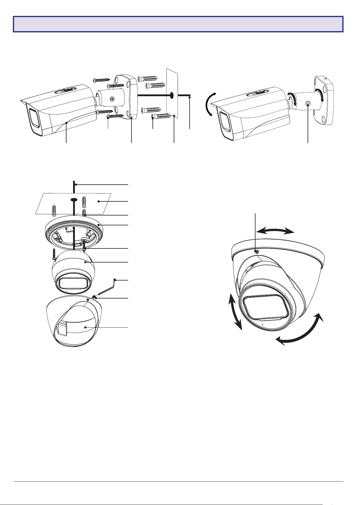
Following the guidelines outlined in Fig. 3.1 to 3.4 mount your surveillance cameras.
1. Loosen the camera mount assembly by adjusting the locking screw with the included wrench.
2. Mark the screw position on the mounting surface.
3. Drill mounting holes for the wall plugs.
4. Drill a larger hole (approx. Ø10mm) so the camera cable can pass through the mounting surface.
5. Pull the cables through the building walls/ceiling from the camera to the recorder.
6. Connect the camera LAN cables, ensuring your camera is sealed away from rain and dust. If installing in an area
where moisture exposure is possible, seal power and video connections with self-amalgamating tape (not included).
7. Afx the camera to the mounting surface using the supplier screws and wall plugs.
8. Reassemble the camera, loosely locking the enclosure using the locking screw and wrench.
9. Connect the LAN cable back to the NVR and view the video feed.
10. Adjust your camera to the desired position.
11. Tighten the locking screw(s) to complete mounting.
NOTE: All cameras feature tri-axis adjustment and can be rotated and tilted in any direction to suit your installation
needs. Simply loosen the locking screw(s) to adjust your camera’s position, then tighten again once nished.
Visit www.vip-vision.com for full user manual and support
11
Page 12
3.2 Mounting Surveillance Cameras (continued)
NOTE: Diagrams shown below assume camera to be mounted on masonry. Cameras mounted on drywall (gyprock,
plasterboard, etc.) will require special mounting screws or toggles (not included).
Self-tapping
screws
Camera Base Surface
Fig. 3.1: Mounting diagram for xed bullet
Wall plugs
Cables
Surface
Wall plugs
Pedestal
Self-tapping screws
Camera
Allen key
Locking screw
Cables
Locking screw
Fig. 3.2: Tri-axis xed bullet adjustment
Locking screw
12
Enclosure
Fig. 3.3: Mounting diagram for xed dome
Fig. 3.4: Tri-axis xed dome adjustment
VIP Vision NVR Quick Start Guide - Version: VIPNVR-Q119
Page 13
4. Footage Playback
4.1 Accessing Stored Footage
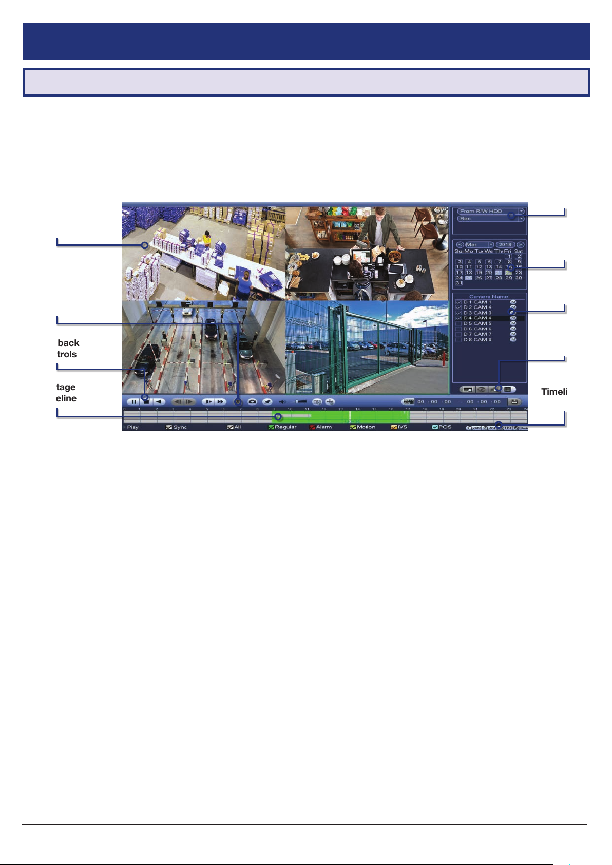
To access footage playback, select the Search button from the Main Menu. Stored footage can be accessed by
searching by date and rened by footage type (Regular, Motion Detection, Alarm, etc). The below image details the
playback interface with footage selected.
After locating desired footage, you can immediately backup the video by using the playback menu. See Section 5.1.1
for more information.
Source
Select
Camera
Display
Date
Select
Smart
Search
Playback
Controls
Footage
Timeline
Fig. 4.1: Four camera view simultaneous footage playback.
Select
Backup
Controls
Timeline
Zoom
4.1.1 Playback Footage by Date 4.1.2 Playback Footage by Smart Search
1. Ensure that the correct HDD is selected and that
REC checked in Source Select.
2. Using the Date Select calendar, choose your date
for footage playback. A coloured date icon indicates
stored footage is available for that day.
3. Using the View Select tabs, choose how many
cameras you wish to view. Using the drop down
menu, choose which cameras you wish to view.
4. The Footage Timeline should populate with stored
footage, indicated by coloured bars in the timeline.
Click anywhere on the timeline to begin footage
playback. Other cameras will automatically sync
their playback to the selected camera.
5. For greater precision playback control, zoom in on
areas using the Timeline Zoom, up to 30 minutes.
6. Using the Playback Controls, you can speed up or
slow down playback, place marks on key footage
times and take snapshots.
NOTE: Smart search requires motion detection to
be recorded to function. You can only Smart Search
playback footage one camera at a time. If Smart Search
is not functioning, check Section 6 for troubleshooting.
1. As detailed in the previous section, use Date Select
to choose the desired date for footage playback,
choosing a single camera only in View Select.
2. Click anywhere on the Footage Timeline to begin
playback. Then select the Smart Search button
(Fig. 4.1).
3. A grid will appear overlaid onto your camera
playback. Highlight an area of interest on the grid.
This will dene the motion detection area that is
used by Smart Search.
4. Select the Smart Search button again to begin
playback of all motion detected events in the area
you selected.
View
By conguring your recording schedule for motion detection and by using Smart Search, you can quickly nd the
footage you require. For Footage Backup, proceed to Section 5.
Visit www.vip-vision.com for full user manual and support
13
Page 14
5. Footage Backup & Viewing
5.1 Backup Footage to USB
Should you wish to preserve recorded footage before it is overwritten, you will need to perform a footage backup.
Footage can be exported from your NVR in a .DAV or .MP4 le. A .DAV le will require conversion for sharing, whereas
an .MP4 le is compatible with most video players on Windows or Mac PCs. Each le type is covered in Section 5.2.
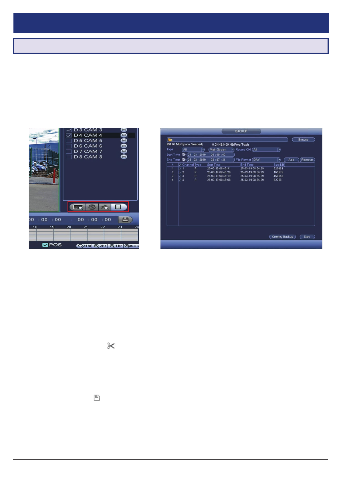
There are two different ways to backup footage to USB: via the Search menu through searching playback footage; and
by performing a direct backup via the Backup menu. Both are accessed via the Main Menu.
NOTE: Backup le type (.DAV/.MP4) selection is only available in the Backup menu. Backup in Search Menu outputs
.DAV les only.
Fig. 5.2: Backup MenuFig. 5.1: Backup Controls in the Search Menu.
5.1.1 Backup Footage via Search Menu 5.1.2 Backup Footage via Backup Menu
Using the Search Menu, nd start/end points of backup
footage by using playback video as a reference.
1. As detailed in Section 4, locate the footage you
wish to backup. Select the desired camera in single
view mode.
2. Using the Footage Timeline, click the approximate
desired time for your backup video start point.
Selecting the Clip Button
Controls (Fig. 5.1) will set your start point.
3. Again, using the Footage Timeline, click the
approximate desired time for your backup video
end point. Select the Clip Button again to set your
end point.
4. Select the Save Button
menu.
5. This process can be repeated to add more clips
from different channels.
6. Plug in your USB device, exiting any automated
prompts, and select Backup to begin backup.
on the Backup
to bring up the Backup
Using the Backup Menu, specify start/end dates &
times across multiple cameras simultaneously. This is
useful for large footage export, such as full days.
1. Select Backup from the Main Menu, or, insert your
USB device and select File Backup.
2. Here, you can select the Type of footage to backup
(default: All), the Start Time and End Time and
what Record Channels to backup video from.
3. Selecting Add will populate the list with individual
video clips ready for backup. Clips can be added or
removed from the backup process using the check
box.
4. Select Start to begin backup.
NOTE: Regular type footage (R) will be split into in one
hour segments, unless Motion Detection type footage
(M) was recorded.
Storage capacity is also shown. Ensure you have the
required USB device storage to accept the backup
video.
14
VIP Vision NVR Quick Start Guide - Version: VIPNVR-Q119
Page 15
5.2 Viewing Footage on a Computer
The following details instructions for viewing footage on Windows or Mac personal computers. Video conversion may
need to take place for viewing on other devices, eg: smartphones, tablets, etc.
Now you have backed up footage to a USB device in .DAV or .MP4 format, you are ready to view on a personal computer.
• .DAV footage can be viewed using the Smart Player Lite program.
• .MP4 footage can be directly viewed using most players, including Windows Media Player & VLC Media Player
Choose which section to proceed with based on what le type you backed up in Section 5.1.
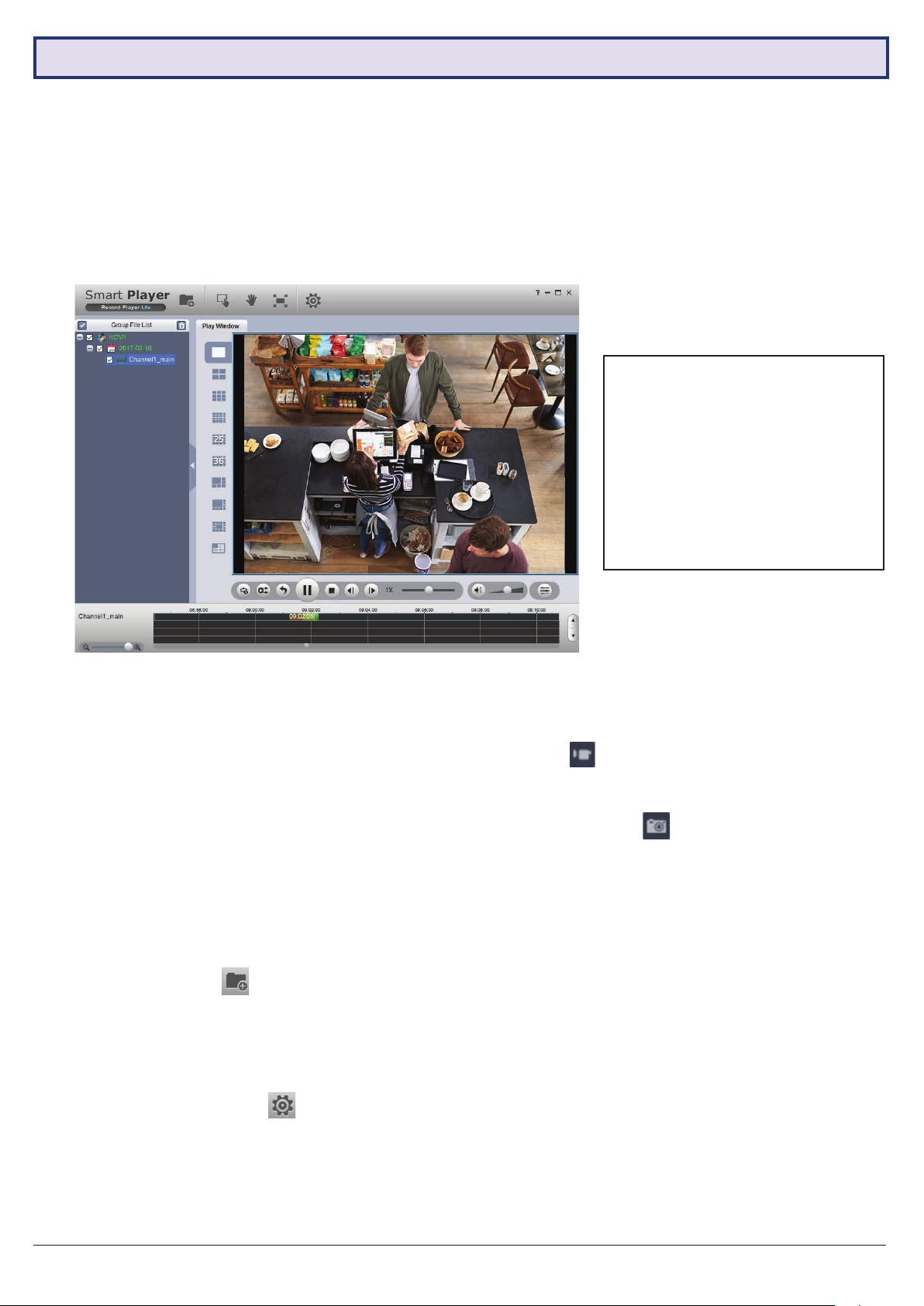
The included Smart Player Lite is for
Windows only.
Smart Player Lite is for viewing
recorded footage only. For CCTV
liveview from your PC, use SmartPSS.
You can download both SmartPSS
and Smart Player (MacOS) from
www.vip-vision.com.
Fig. 5.3: Footage playback using the included Smart Player Lite for Windows
5.2.1 Viewing .DAV Video Files on PC with
Smart Player Lite
Note: Smart Player Lite is automatically copied onto
the USB device when performing footage backup from
the NVR.
1. The .DAV le format is playable only by your NVR
or the Smart Player Lite media player and cannot
be played on mainstream media players without le
type conversion.
2. To view .DAV footage in Smart Player Lite, either
click the Add Files
or drag & drop the le onto a selected play window.
3. Using the .DAV le, Smart Player Lite adds
functionality similar to your NVR in footage playback,
such as synchronous playback of multiple channels.
4. Open the Options menu
the directories and formats for saved snapshots
(.BMP/.JPG) and videos (.DAV/.AVI). You can also
adjust video aspect ratio and other options.
button and select the le,
. Here, you can set
5. You can export clips by pressing the Record
button
end recording.
6. Similarly, you can take snapshots by pressing the
Snapshot button
once to begin recording, then again to
once.
5.2.2 Viewing .MP4 Video Files
The .MP4 le format is a common video format,
compatible with Windows Media Player and most other
video players.
.MP4 videos can also be played by VLC Media Player.
This free open source player is available across many
platforms, including:
• Desktop: Windows, Mac OS and Linux
• Mobile: Android and iOS
1. Access your USB device and open your backup
.MP4 footage video using one of the media players
mentioned above.
2. .MP4 les cannot be viewed using Smart Player Lite.
They do not retain time/date data like .DAV les.
Visit www.vip-vision.com for full user manual and support
15
Page 16
6. Intelligent Functions
NOTE: Before enabling Face Detection or Tripwire, ensure that you’ve congured Intelligent recording schedules (refer to
2.1.5 Conguring Recording Schedules), or these functions will not work.
Intelligent Video Systems (IVS) let your CCTV system go beyond surveillance, delivering advanced & powerful detection
tools. When properly congured, these functions can alert you to suspicious activity in real time via email/smartphone
notication and let you easily search through surveillance footage via event history.
• Face Detection - Uses smart technology to detect human faces, snapshotting and saving them in a directory.
• Tripwire - Detect when any object crosses a set warning line in the video.
• Intrusion - Detect when any object intrudes inside a set zone in the video.
• Abandoned/Missing Object - Detects if an object has been left/taken from a set zone in the video.
NOTE: Only one channel can use Face Detection. Face detection and other IVS cannot be used at the same time!
6.1 Face Detection (Requires supporting camera)
6.1.1 Enabling Face Detection
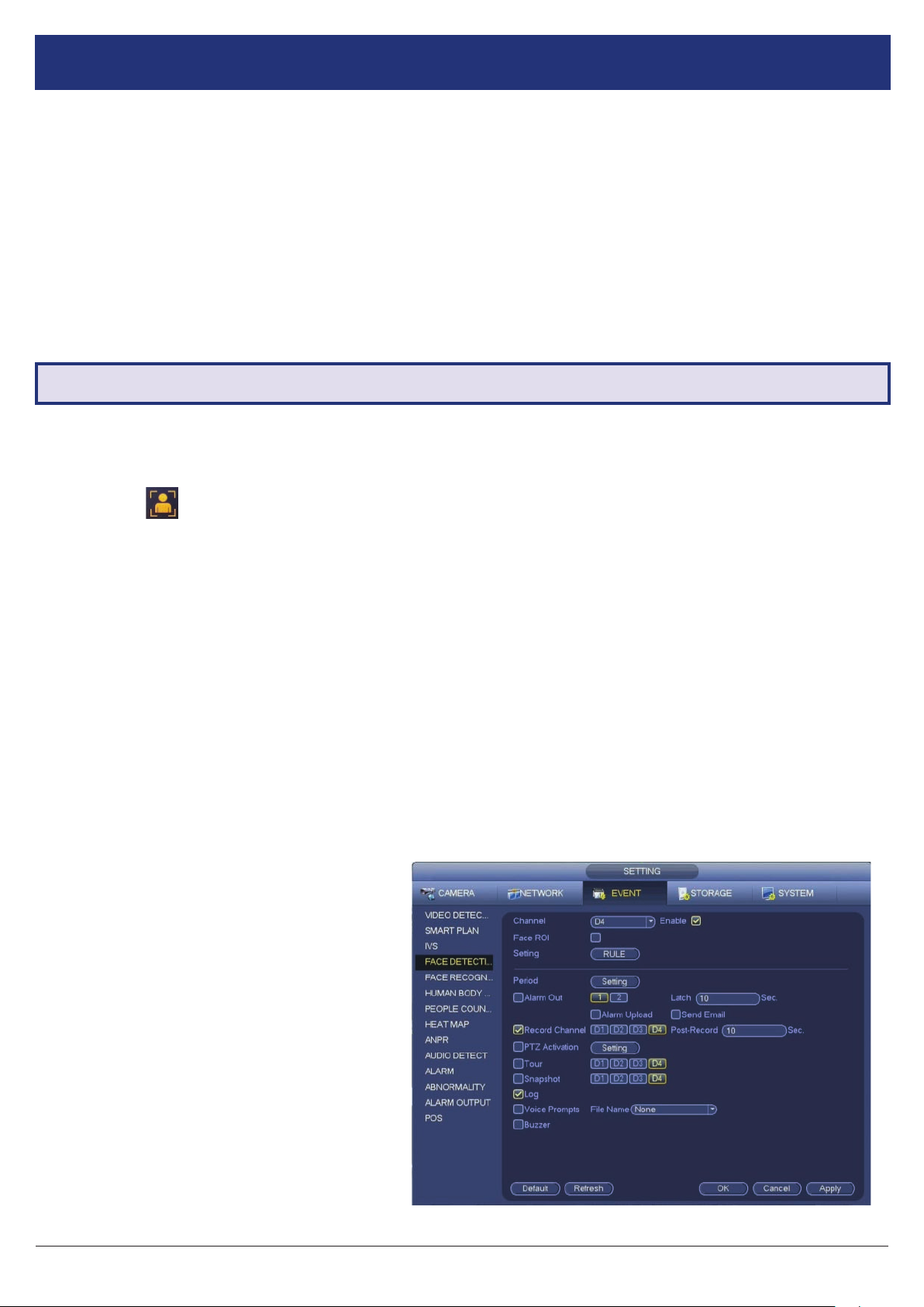
1. From the Main Menu, select Event and then Smart Plan. Select the camera with face detection functionality.
2. Click the Face Detect icon and then Apply to enable face detection. The icon will turn orange when enabled.
3. Select the Face Detection tab and select the Channel that you want to enable face detection. Click the Enable box.
4. Select Rule to draw the motion detection area of the camera. If the face appearing in the camera is bigger than the
box drawn, it will trigger the face detection alarm (smaller box = higher sensitivity).
6.1.2 Face Detection Trigger
The other options on the Parameters tab congure the actions taken after a face detection event is triggered.
1. Period sets the times of day that Face Detection is activated (always on by default).
2. Alarm Out sets an external alarm to activate whenever a face is detected.
3. Latch Time sets how long the system waits after detecting a face before detecting again (10 seconds by default).
4. Alarm Upload updates the alarm system status on the network (Unused for this system).
5. (Requires internet connection & setup) Send Email noties a specied email address whenever a face is detected,
also attaching a photo of the face.
6. Record Channel sets which camera to
record to when the face detection alarm is
triggered.
7. Post Record sets the amount of time
recorded after the face is detected. This clip
can be played back while searching through
faces (10 seconds by default).
8. (PTZ camera only; not included) PTZ
settings set PTZ behaviors in response to a
face detection, such as selecting a Tour to
perform, etc.
9. Buzzer sets the NVR to beep whenever a
face is detected.
10. Voice Prompts plays a designated .wav le
in response to face detection.
11. Click Apply to save changes.
16
Fig. 6.1: Face Detection Parameters menu.
VIP Vision NVR Quick Start Guide - Version: VIPNVR-Q119
Page 17
6.1.3 Smart Search (Face Detect)
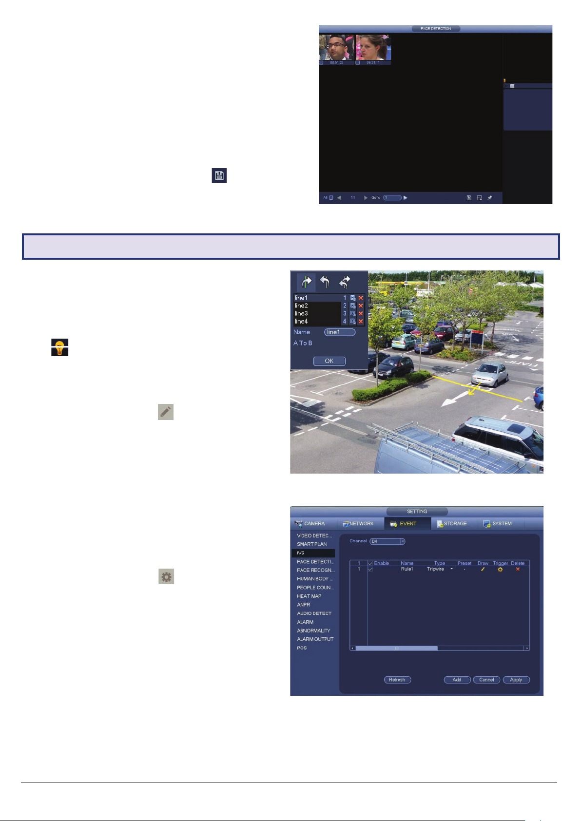
1. From the Main Menu, select Smart Play and then
Face Detection.
2. From here, you can search through every face
detection event in a certain period of time.
3. If any faces were detected in the specied timeframe,
they will be displayed along with a timestamp.
Double-click on one of the faces to see the full
snapshot.
4. To backup recorded footage, click the
Save icon.
6.2 Tripwire & IVS Setup
6.2.1 Tripwire Setup
1. From the Main Menu, select EVENT then the Smart
Plan tab.
2. Select the Channel you want to set up. Click the
icon then Apply to enable the IVS.
3. Select the IVS tab. Select a Channel, then click Add
button at the bottom. This will create a new IVS
setting (Tripwire by default).
4. Click the Draw button
screen (Fig. 6.3).
5. Left-click on the screen to start drawing the Tripwire
line. Left-click again to nish the line (optionally, you
can add additional corners to the line by continuing
to left-click). Right-click to nish placing the line.
6. In the top left window, you can alter the Direction
that the line must be passed from to activate the
event, as indicated by the arrow going across the
line (A to B, B to A, or both ways).
to bring up the Draw
Fig. 6.2: Face Detection Smart Search.
Fig. 6.3: Tripwire Draw screen.
7. Click OK to nish.
8. Click the Trigger Button
menu, conguring what actions are taken once the
IVS event is triggered. These conguration options
are identical to the ones shown in 6.1.2 Face
Detection Trigger.
9. Click OK to nish.
10. Click the Enable box to turn on the IVS rule.
11. Click Apply to save changes. If done correctly, you
will see the Tripwire in live view.
to bring up the Trigger
Fig. 6.4: IVS setup screen.
6.2.2 Intrusion/Abandoned/Missing Setup
Intrusion, Abandoned Object and Missing Object are all set up in similar ways to Tripwire - simply select which IVS you
want to set up from Type menu (Fig. 6.4).
Visit www.vip-vision.com for full user manual and support
17
Page 18

7. Troubleshooting
This concludes the Quick Start Guide covering the basic functionality of your VIP Vision Surveillance system. Should
you encounter any difculties with your setting up and using your system, please rst refer to the tables below or visit
the Contact Us section on the VIP Vision website at www.vip-vision.com.
Area Menu Navigation Guide Ref.
NVR Security Setup Main Menu -> System -> Account Section 2.1.2
Changing General Settings Main Menu -> System -> General Section 2.1.4
NVR Network Setup Main Menu -> Network -> TCP/IP Section 2.1.5
P2P & Remote View Setup Main Menu -> Network -> P2P Section 2.1.5
Conguring Cameras Main Menu -> Camera -> Encode Section 2.1.6
Changing Recording Schedule Main Menu -> Storage -> Schedule Section 2.1.7
Accessing Playback Footage Main Menu -> Search Section 4
Backing Up Footage Main Menu -> Backup Section 5
Problem Troubleshooting Guide Ref.
• Ensure that the power cable is rmly connected to the recorder and to
The NVR won’t power on.
The NVR is not being displayed
on the monitor.
Cameras aren’t displaying live
video.
the wall socket.
• Conrm that there is power from the outlet.
• Ensure the display cable is rmly connected to the recorder & monitor.
• Ensure you have selected the correct input on your monitor.
• Test the recorder’s display output with different monitor.
• Ensure that you are not in playback mode, right mouse click to exit.
• Ensure power is connected to cameras and that the BNC connectors
are rmly connected to the NVR via the camera cable.
• Swap with known working cables and cameras to test.
Section 1.2
Section 1.2
Section 1.2
The NVR is displaying No HDD. • Check if the HDD is properly connected. -
• Check if the HDD is installed and properly connected.
The NVR is not recording video.
Motion is not being detected or
recorded by the NVR or unable
to Smart Search.
Cannot connect to NVR on
smartphone or tablet.
The recorder will not detect a
USB device for backup.
Face Detection / IVS features are
not working correctly.
• Check that the recording method you have chosen to implement is in
use.
• By default motion detection is enabled, however, check by navigating
to Main Menu -> Setting | Event -> Video Detect. The Enable check box
should be checked for all relevant channels.
• Ensure that a period has been selected in the Recording Schedule for
motion detection recording and that the period is lled in yellow.
• Check motion sensitivity and adjust motion detection area, see:
Main Menu -> Setting | Event -> Video Detect: Region | Set.
• Ensure that the NVR & device are connected to the Internet and that the
connection is strong enough to receive video (min. 3G speeds).
• Ensure that the admin password is correct in the iDMSS/gDMSS/
Easyviewer app.
• Ensure the extra stream settings are set to recommended settings.
• Ensure that the USB drive is formatted to FAT32 or NTFS.
• Try using another USB ash drive to test compatibility.
• Ensure that lntel (blue) recording schedules have been set up in Schedule.
• Ensure that Enable has been checked for each rule on the IVS screen.
Section 2.1.7
Section 2.1.5
Section 5.1
Section 2.1.7
Section 6.1
Section 6.2
-
18
VIP Vision NVR Quick Start Guide - Version: VIPNVR-Q119
Page 19

Notes
Visit www.vip-vision.com for full user manual and support
19
Page 20

Crucial Evidence. Always.
For more information, please visit:
www.vip-vision.com
Version: VIPNVR-Q119.1
 Loading...