

Page 1
©2017 CORNET Microsystems Inc., 1400 Coleman Ave #C28 Santa Clara, CA 95050 USA Tel: (408)9690205
www.cornetmicro.com
ED88TPlus V.2.0 02/272018
LED
color
RF
Power
level
RF Power
density
LF600/LF30
level
E
-
field
level
Indication Action
RED3
-
5 dBm
up
0.18 w/m
2
30uT/3uT
up
500
v/m
Italy RF safety
standard (0.1w/m2)
Caution!
RED2 -10 dBm 0.058 w/m2 20uT/2uT
200
v/m
Swiss RF safe
ty
standard (0.04w/m2)
Caution!
RED1 -15 dBm 0.018 w/m2 10uT/1uT
100
v/m
Russian RF safety
standard (0.02w/m2)
Caution!
YELLOW3 -20 dBm 5.8 mw/m2 5uT/0.5uT
75
v/m
Safe*
YELLOW2 -25 dBm 1.8 mw/m2 2uT/0.2uT
50
v/m
Safe*
YELLOW1 -30 dBm 0.58 mw/m2 0.5uT/0.05uT
30
v/m
Safe*
GREEN3 -35 dBm 0.18 mw/m2 0.2uT/0.02uT
20
v/m
WiFi Wireless LAN
typically in this range
Safe*
GREEN2
-
40 dBm
down
0.06 mw/m
2
0.2uT/0.02uT
down
10vm Some signal source
around
Safe*
CORNET® ED-88TPlus Electrosmog meter user’s manual v.2
02/27/2018
CORNET Microsystem Inc., ED-88Plus Electrosmog meter is a Tri-mode device for quick measurement of
both High frequency (RF) Electromagnetic wave field strength/power density level, Low frequency (LF)
Magnetic field level(Gauss, Tesla), and Low frequency (ELF) Electric Field(V/m) for living environments. It is
an excellent device for individual or company with Ele ctromagnetic wave safety concerns. It has RF
bandwidth of 100MHz to 8GHz with high sensitivity (0.5u w/m² to 1.8w/m²), LF bandwidth of 50Hz to 10KHz (or
50Hz to 1KHz) with sensitivity of 0.1uT to 60uT(1mG- 600mG) or 0.01uT to 1uT(0.1mG to 10mG), and E-field
bandwidth of 50Hz-50KHz with sensitivity of 10v/m to 1000v/ m. The RF Frequency display function (100MHz-
2.7GHz) can detect very short burst of digital RF do wn to 100usec. Data Logging function is also included.
Applications:
- High frequency RF Electromagnetic wave field stren gth, power density and frequency measurement
- Low frequency LF Magnetic field measurement (Gauss meter function)
- Low frequency ELF Electric field measurement (E- field meter function)
- Mobile phone base station antenna radiation power density measurement
- Wireless communications, Analog & Digital RF (AM/FM, T DMA, GSM, DECT, CDMA,3G,4G)
- RF power measurement for transmitters
- Wireless LAN (Wi-Fi), Bluetooth, Ultra- wide-band detection, installation, optimization
- Spy camera, wireless bug finder, IOT devices
- Cellular/Cordless phone radiation safety level, Electrical Utilities SMART METER radiation level
- AC power line, High voltage tower, power Transformer, motors and small appliance EMF
- Microwave oven leakage detection
- Personal living environment EMF safety evaluation
Usage guide:
(1) Put the 9V battery in the ED88Plus, Handle the unit with r ight hand in vertical direction, and turn on the
volume/power switch to turn on the power, it will come up with RF meter mode.
(2) The RF sensor is located in the left hand side of the ED88PLus ; the LF sensor is located in the right
hand top side of the ED88Plus, the E-field sensor is located in the middle top side of the ED88Plus,
please do not cover the sensor area with hand or ot her objects.
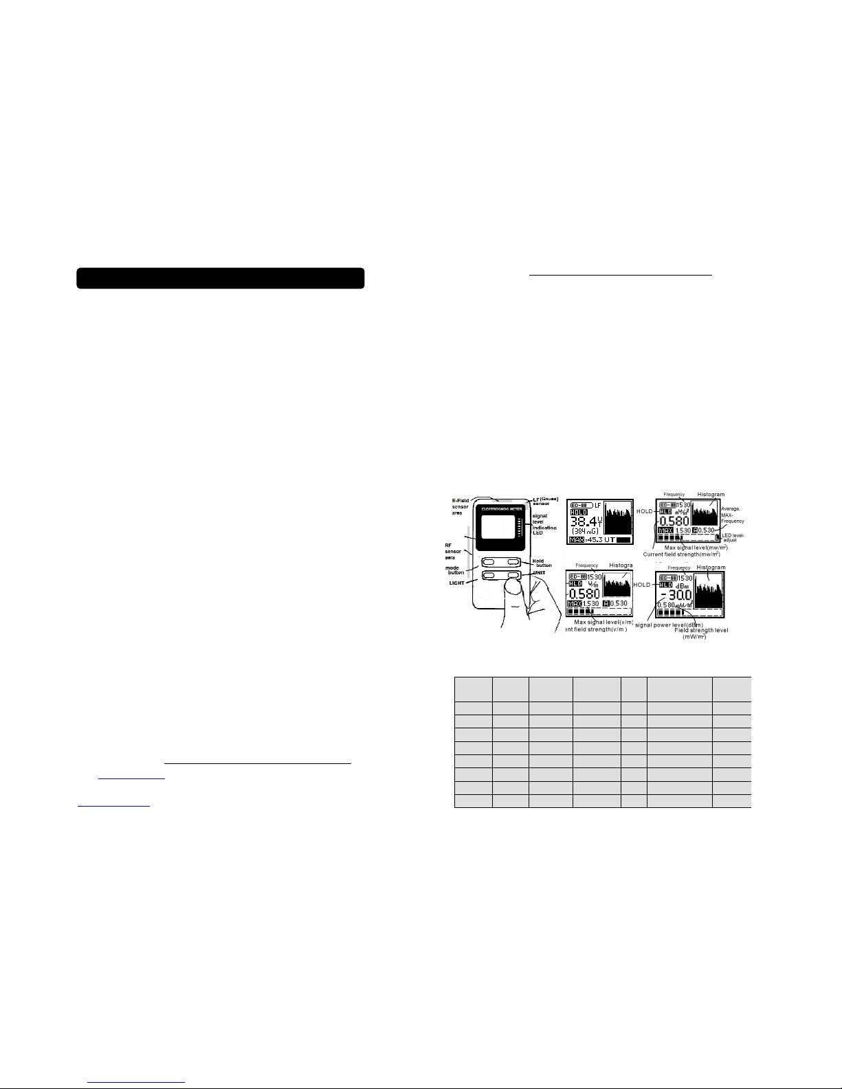
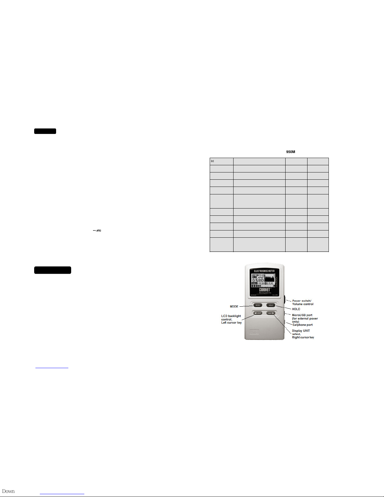
(3) There are 4 push button on the ED88Plus: “Mode”, “Hold”, ”LI GHT”, and “UNIT” button, “MODE”
button is used to switch in between RF mode, two LF modes, and E-field mode. The “Hold” button is
used to freeze the data reading of the ED88Plus.
(4) R F mode: measured RF field strength/power density is shown on the digital LCD display
(with dBm, v/m, or mw/m²). 8 LED lights with Red, Yellow, and Green color on the right hand
side of LCD window are used for quick RF signal level indications. 3 Red LEDs are used to
indicate the 3 safety ranges. The power level of each L ED can be found in the table on the
ED88Plus back panel. Frequency of signal detected is displayed on the LCD display.
(5) LF mode: measured LF magnetic field strength is shown on the digital LCD display (with uT
and mGauss). Two LF modes can be selected by “Mod e” button: (a) LF30mode (0.1mG-10mG)
and (b)LF600 mode (1mG-600mG). 8 color LED lights are also available to show the relative
strength of the magnetic field.
(6) E- field mode: measured ELF electric field strength is shown on the digit al LCD display with V/m.
(7) Hi stogram: previous 30 signal level readings are recorded and shown as moving graph
on the LCD display for RF, LF, and E-field modes . It can be used for finding direction of signal source
and recording bursts from digital RF signals such as signa ls from AC smart meter.
(8) H old &UNIT: HOL D button can be used to halt the data measuremen t of the ED88Plus, a “HOLD”
Mark will shown on the LCD screen to indicat e the “Hold” condition. Push the “HOLD” button again the
ED88Plus will exit from the “Hold” condition. “UNIT” button c an select the mw/m2,v/m,or dBm unit.
(9) M AX: Maximum measured data value since the last po wer-on is shown on the LCD display.
(10) Average: average or peak average value is displayed on the LCD with “A” or “P” mark. It can be
used to estimate the duty cycle of the digital RF burst signals or the average of pe ak signal level.
(11) Sound function & LCD backlight: Toggling the “LIGHT” button can turn-on/off the LCD back light a nd
the Audio Sound function, ( a “S” mark on the LCD indicates the sound mode i s on). Wheel Volume
control can be used to adjust the sound level. Audio Sound can be used to detect very low level RF
signals (down to 0.05uw/m2) especially for the modern digital RF burst signals. In order to re duce the
battery current consumption please remember to turn-off the LCD back light or the sound when it is not
needed.
(12) Data Logging menu: Push and hold the “UNIT” button then click the “MODE” button to go into
LoggerSetup menu. Please see the “ED88TPlus Data Logging user G uide” from
www.cornetmicro.com for details of the Data Logging functions.
(13) SysSetup Menu: Push and hold the “UNIT” button then push the “HOLD” button
to get into the SysSetup menu. Use the “>” button to move the cursor in the Menu
and use the “<” button to enable/disable the functions In the SysSetup menu:
(a) EXIT: exit the SysSetup menu, return to normal mode
(b) RF level Unit select: select default mw/m2, v/m, or dBm mode when meter is powered on.
(c) LED Level: used to adjust the color LED segment display level for custom safety standards
OFF,-5,-10,-15, or -20dB. (use -20dB for “SBM 2008 Building Biology Testing Methods” )
(d) Average/Frequency : select Peak average, All average, or Frequency of MAX value display.
(e) MAX_Clear bit: If the MAX_Clear is “ON” the MAX value can be cleared by toggling the “ HOLD”
button. If it is “OFF” the MAX va lue can be cleared only by power-off the meter.
(f) Alarm: ON/OFF or one of the 8 trigger levels( 0, -5,-10,-15,-20,-25,-30,-35dBm) can
be selected to trigge r the audio Alarm. *(Alarm function is used in RF mode only).
(e) RESET: reset to defau lt (mw/m
2
,LED Level OFF, MAX_CLEAR ON, Alarm OFF,PeakAvg).
(g) SAVE: push the “<” button to save the chang es of setup to EEPROM memory. Do not
power off meter, Wait until save is done! (EXIT without SAVE to memory the
changes will still functional, but it will lost if the meter is power-of f ).
(14) The LF30 mode: has hig h sensitivity (0.1mG-10mG), but with lower freque ncy range
(50Hz – 1KHz) to reduce the high frequency noise. (The Histogram and LED
segment display can go up to 30mG)
The LF600 mode: with sensitivity (1mG-600mG), has higher frequency coverage (50Hz -10KHz).
When measuring the high frequency digital/pulse type of si gnals,(such as switching power supply)
the LF30 mode might have lower reading than the LF600 mode, this is due to the lower frequency
coverage range of the LF30 mode.
( 15) While in LF (magnetic/electric field measurement) or E-field mode, p lease hold the ED88 steady to
get the good stable reading , avoid fast moving of the ED88 to prevent the sudden change of the
reading caused by the Earth magnetic field or the induced electric field of nearby objects.
( 16) AC Smart Meter radiates RF signal in short burst every few minutes, u se MAX function and
Histogram function of ED88, and wait a few minutes to capture the RF signals from smart meter.
Field strength/power density readout:
ED88Plus use 8 high brightness LED to indicate the measured power density with 3 safety
Indications of three countries
.
*Action is reference to ICNIRP (for reference only).
Page 2
©2017 CORNET Microsystems Inc., 1400 Coleman Ave #C28 Santa Clara, CA 95050 USA Tel: (408)9690205
www.cornetmicro.com
ED88TPlus V.2.0 02/272018
NOTE:
Most high frequency RF antenna such as Mobile phon e base station is vertical polarized
(in vertical direction), therefore while in RF mode, the ED88 is normally used in vertical
direction. For LF mode, the LF sensor is located in the top right hand of the ED88 and the
meter is normally used in Horizontal position in LF mode. For E-field mode, the E-field sensor
is located in the top middle of the meter, point the sen sor to the ELF source. Please rotate the
meter to find the maximum reading direction in eithe r case. The maximum reading will also
increase as you approach the source. ED88 can be used to find the location of signal source.
Most of modern communication devices (Mobile ph one, Wireless LAN, Wi-Fi, etc.,) use
digital RF burst signals. When measuring this type of signals, several LED lights will blinking
at the same time. this is normal and it can be used as an indi cation of burst type of RF signals.
For continues waves (AM/FM) signals, the LED light will be stable. ED88 measures the peak
power density of the signal with very fast sampling time. It is more accurate than the needle style
of readout which only shown the average value of signal p ower most of the time.
Electromagnetic wave field strength/power densit y reduces very fast with distance (distance
square), keep a good distance from the high freque ncy RF signal source can reduce the high
frequency radiation effect. Alumina foil or window sun reflector film (silver color) can be used
as an effective and low cost shielding material for most of RF radiations.
ED88 is designed for quick living environment RF radi ation evaluation and is for reference use
only. Official RF safety radiation measurement procedure is complicate and should be handled
by trained technical person with lab instruments. Safety range standard listed below is for
reference only. ED88 is not a medical instrument, Please do not use it in medical, legal,
commercial rental purpose or other related applications. . (for personal use only)
Turn the volume control to minimum first before plug in the earphone to the ED88 to avoid
damage to your ear by accident from high level audio sound produced by digital RF signals.
The audio sound output of the sound function is the d emodulated RF signal, it is good for AM
and modern digital RF signals (pulse/burst ) detecti on, it is not for FM or constant amplitude RF
signals or LF/ELF modes. it is an excellent tool for RF signal type indication. (different RF
signal such as Wifi, GSM, DECT,
…………
.etc., all has different sound frequency signature of the
demodulated RF signal) and for very low level signal dete ction.
When in E-field mode, the electric field induced b y human body or large objects nearby can
affect the measurement results, hold the ED88 by hand on the lower right side of the meter, do
not cover the E-field sensor area (top of the meter) b y hand or other objects, keep away from
large metal door or objects. Point the top of the ED88 to the high voltage AC power line (with
ED88 at least 1 meter above the ground) when measuri ng the VLF/ELF E-field radiation from AC
power lines or towers. Average value is displayed in E-field mode to reduce background
noise, Reading will be lower for narrow spike type of E-field radiation such as from FL lamp.
Specification
Sensor type: Electric field sensor and Magnetic field sensor
Frequency range & Sensitivity: RF: 100MHz to 8GHz
(-60dBm to +5dBm),(0.5uw/m2 to 1.8w/m2),
(14mv/m to 26.2v/m)
LF1: 50Hz to 10KHz (0.1uT to 60uT)/(1mG to600mG)
LF2: 50Hz to 1KHz (0.01uT to 1uT)/(0.1mG to 10mG)
E-field/ELF: 50Hz to 50KHz (10v/m to 1000v/m)
Frequency display: for RF mode only, 100MHz-2.7GHz,
-35dBm minimum signal input required
RF Peak power measurement: 0.5uw/m² to 1.8w/m²
Display type: digital LCD graphic display
Unit of measurements: dBm, mw/m², v/m, uT, mG, MHz
LCD back light: 15 seconds auto-off and manual on/off control
Display of data: LCD 4 and 5 digit, 8 LED color segment,
Moving Histogram (level/time) of previous 30 recorded data,
Analog segment bar
Data update rate: Sampling rate: 10000/sec. Display update rate: 2/sec.
Error rate: RF: +/- 3.5d Bm, LF: 20%, E-field: 25%
Functions: Hold, Max, Average, Sound signature, Alarm, Frequency
Sound & Alarm: Sound on/off/volume control, programmable Alarm triggering level
Safety standard indication: 3 safety range indication by 3 Red LED, a djustable LED level
Data Logging: 1000 data storage point memory for logging/recording measured RF signa l level
Battery used: 9V alkaline battery or external power supply through USB port (5V)
Battery life: >20 hours
The European Community provided genera
l guidelines in its Council
Recommendation of July 1999.1 ICNIRP published similar guidelines in
April 1998.2 Table I gives a sampling of the international and national
field-strength limit values for the general public and continuous
exposure (for Reference only !)
950Mhz 1850Mhz
1W/m2 = 1000mW/m2,
1mW/m2 = 1000uW/m2 = 0.1uW/cm2 = 0.0001mw/m2
1uW/m2 = 0.001mW/m2 = 0.0001uw/cm2
1uT = 10mG, 0.1uT = 1mG
1mV/m = 0.001V/m
International Council Recommendation 1999/519/EC
42 V/m
(4.75W/m2)
59 V/m
(9.25W/m2)
International ICNIRP Guidelines, April 1998
42 V/m
(4.75W/m2)
59 V/m
(9.25W/m2)
Austria ÖNORM S1120
49 V/m
(6.33W/m2)
61 V/m
(10W/m2)
Belgium Belgisch Staatsblad F.2001-1365
21 V/m
(1.18W/m2)
30 V/m
(2.31W/m2)
Germany 26. Deutsche Verordnung
42 V/m
(4.75W/m2)
59 V/m
(9.25W/m2)
Italy Decreto n. 381, 1998
6 V/m
(0.1W/m2)
20 V/m
(1W/m2)
6 V/m
(0.1W/m2)
20 V/m
(1W/m2)
The Netherlands Health Council
51 V/m
(6.92W/m2)
83 V/m
(18W/m2)
Switzerland Verordnung 1999
4 V/m
(0.04W/m2)
6 V/m
(0.1W/m2)
United States IEEE C95.1
49 V/m
(6.33W/m2)
68 V/m
(12W/m2)
China
Draft: National Quality Technology
Monitoring Bureau
49 V/m
(6.33W/m2)
61 V/m
(10W/m2)
Japan
Radio-Radiation Protection Guidelines,
1990
49 V/m
(6.33W/m2)
61 V/m
(10W/m2)
 Loading...