

Page 1

GET FOCUSED
Congratulation on your purchase of a Cornerstone
™
high-performance, high-resolution, large-screen
monitor. The best monitor in the industry.
USERS GUIDE
p1600:p1500
:)
www.BigMonitors.com
Page 2

READ THE INSTRUCTIONS INSIDE CAREFULLY.
KEEP THIS USER MANUAL FOR FUTURE REFERENCE.
For future reference, record the s eri al number of your color monitor.
SERIAL No.
The serial number is locat ed on the rear of the monitor.
®
This monitor is
E
NERGY STAR
compliant when used with a computer
equipped with VESA DPMS.
®
The
E
NERGY STAR
emblem does not represent EPA endorsement
of any product or service.
®
As an
E
NERGY STAR
product meets the
Partner, Cornerstone has determined that this
®
E
NERGY STAR
guidelines for energy effici ency
1
.
Page 3

NOTE:
* The information in this manual is subject to change without notice. The manufacturer assumes no responsibility for
any errors that may appear in this manual.
* The reproduction, transmission or use of this documents or contents is not permitted without express written
authority.
TRADEMARK ACKNOWLEDGEMENT:
VGA is a registered trademark of International Business Machines Corporation.
VESA is a trademark of a nonprofit organization, Video Electronics Standard Association.
E
NERGY STAR
®
is a trademark of Environmental Protection Agency (EPA).
REMARQUE:
* Les informations contenues dans ce manuel peuvent être modifiées sans préavis. Le constructeur n’accepte
aucune responsabilité pour les erreurs qui peuvent éventuellement apparaître dans ce manuel.
* Tous droits réservés, y compris celui de traduction, reproduction, duplication (même partielles) par quelque
procédé que ce soit.
MARQUES DÉPOSÉES:
VGA est une marque déposée d’ International Business Machines Corporation.
VESA est la marque d’une organisation sans but lucratif, la Video Electronics Standard Association.
E
NERGY STAR
®
est une marque de l’ EPA (Environmental Protection Agency, USA).
HINWEIS:
* Änderungen der Daten in dieser Bedienungsanleitung sind vorbehalten. Der Hersteller übernimmt keine Haftung für
jegliche in diesem Handbuch eventuell enthaltenen lrrtümer.
* Alle Rechte vorbehalten, insbesondere (auch auszugsweise) die der Übersetzung,
des Nachdrucks, der Wiedergabe durch Kopieren oder ähnliche Verfahren.
GESCHÜTZTE WARENZEICHEN:
VGA ist ein eingetragenes Warenzeichen der International Business Machines Corporation.
VESA ist ein Warenzeichen der Video Electronics Standard Association, einer Organisation ohne
Erwerbscharakter.
E
NERGY STAR
®
ist ein Warenzeichen der Environmental Protection Agency (EPA).
NOTA:
* La información contenida en este manual está sujeta a cambios sin previo aviso. El fabricante no se
responsabiliza de los errores que puedan aparecer en este manual.
* La divulgación y reproducción de este documento, así como el aprovechamiento de
su contenido no está autorizado, a no ser que se obtenga el consentimiento expreso
para ello.
RECONOCIMIENTO DE MARCAS
VGA es una marca registrada de International Business Machines Corporation.
VESA es una marca registrada de una organización sin ánimo de lucro, Video Electronics Standard Association.
E
NERGY STAR
®
es una marca de Environmental Protection Agency (EPA).
NOTA:
* Tutte le informazioni di questo manuale sono soggette ad essere modificate senza preavviso. Il costruttore non si
assume responsabilità per errori che possono essere riportati sul manuale.
* Tutti I diritti riservati per tutta l’opera (o per parti di essa), in particolare per ciò riguarda la traduzione, la copia, la
riproduzione o procedimenti simili.
MARCHI DI FABBRICA RICONOSCIUTI.:
VGA è um marchio di fabbrica regisrato da International Business Machines Corporation.
VESA è il marchio di riconoscimento della organizzazione a non-profitto, Video Electronics Standard Association.
E
NERGY STAR
®
è il marchio di fabbrica della Eviromental Protection Agency (EPA).
2
Page 4

CONTENTS
FEATURES
INSTALLATION
OPERATION
POWER SAVING SYSTEM
PLUG & PLAY
SIGNAL CHECK
TROUBLESHOOTING
SPECIFICATIONS
CAUTIONS
WARRANTY
CUSTOMER SUPPORT
Tables:
Table 1. Adjustment
Table 2. Power Saving System
Table 3. Signal Check
Table 4. Troubleshooting
Table 5. Standard Settings
Table 6. Standard Settings (Pre-loaded)
Table 7. Pin Assignment
...................................................................................................... 4
................................................................................................ 6
.................................................................................................... 9
............................................................................. 17
.................................................................................................. 17
.............................................................................................. 17
..................................................................................... 18
........................................................................................... 19
................................................................................................... 23
..................................................................................................... 39
.................................................................................. 40
......................................................................................... 11
........................................................................ 17
...................................................................................... 17
................................................................................. 18
............................................................................... 20
.................................................................................. 22
.......................................................... 20
3
Page 5

FEATURES
The following features are provided in this Color Monitor.
Sharpest Focus and Highest Contrast
Flat screen Enhanced Dot Pitch (EDP) CRT with anti-glare, dynamic focus circuit, dark
glass and an INVAR shadow mask gives the sharpest focus and highest contrast to
minimise eye fatigue.
Wide-range Multi-Scanning
Automatic scanning and automatic adjustment to conform with a wide range of scanning
frequencies and user requirements.
Digital Picture Control Function
Position, size, pincushion, trapezoid, parallelogram etc. are adjustable by digital controls.
Geometry settings can be stored for different H/V frequencies. Microprocessor-based
user preset functions can store 32 sets of geometry settings excluding the standard
factory settings.
Digital Color Control Function
Red, green, and blue color balance is adjustable by digital control. An adjusted color
setting can be stored and recalled by the color select function.
Power Saving System
The Environmental Protection Agency (EPA) has established a voluntary program by
which manufacturers enable computer products to go into low power states while not
being used. This monitor has a low power “sleep” mode, which is compliant with the
EPA requirements for the
energy. Please refer to the section of “POWER SAVING SYSTEM” for details.
NERGY STAR
E
®
program, and will assist you in conserving
On Screen Display
An On Screen Display function that allows easy access to adjust all operations from the
front panel.
Plug & Play
This monitor is VESA DDC1/2B compliant when used with a computer compliant with
VESA DDC (Display Data Channel).
DMS Mode
This monitor provides DMS (Dynamic Motion picture System) mode, which increases the
brightness of the screen to be suitable for motion pictures.
4
Page 6

Color Adjustment
Color adjustments give the user the flexibility to customize color settings for different types of
applications. Text based applications that use light backgrounds with black text benefit from cooler
bluish white “paper like” colors. Color / graphics applications like web page development and pre
press benefit from warmer reddish color adjust ments. Optimizing the monitors col or settings will
provide for more accurate c ol or reproduction and accuracy.
Cornerstone monitors are optimized at the factory for t ext based applications. The default color
setting of 9000K provides paper white performance that is criti cal for today’s business appli cations.
When you set up a Cornerstone m onitor, you c an adjust the “white point,” or t he color tem perature
using the direct digital us er cont rols , I f your applic ati on is c olor int ensi ve, you would choose a white
point of 6500K. For printed reproduction, a white point of 5000K will match standard viewing
conditions.
Source Application Color temperature
Cornerstone Monitor Text Based 9000K
Blue
Average Daylight 6500K
Television Color Intensive 6500K
Cool White Fluorescent 6500K
Print Reproductions Photo Reproduction 5000K
Color
Red
Warm
Tungsten Lamp 2800K
Sunlight at Sunrise 2000K
See COLOR SELECT on page 12 for more details.
5
Yellow
Warme
r
Page 7

INSTALLATION
Before installing, read the chapter “CAUTIONS” carefully.
Checking the contents
Check whether the consignment agrees with the details in the following delivery note.
Should you discover that the equipment has been damaged during transport or that the
consignment does not correspond to the delivery note, notify your dealer immediately.
Delivery Note
: one Monitor
one Power Cord
one Signal Cable
This Floppy Disk
NOTE:
Keep the original packing material for future reshipment.
6
Page 8

INSTALLATION (Continued)
Connecting the monitor
Front Cover
Screen
Power Switch
Rear Cover
AC Inlet
Signal Input
Tilt & Swivel
Base
Front View
Power Cord
Rear View
to a power outlet to the host
of the correct voltage Signal Cable computer
1. Installation
Install the monitor in an suitable environment.
Do not place the monitor on an unstable base.
Do not expose the monitor to rain, moisture, dust, corrosive gases, vibrations, etc.
so as to prevent electrical shock or fire hazard.
Avoid placing the monitor in direct sunlight or near heating appliances.
2. Signal Cable Connection
(1) Use video signal cable which is included in the carton box.
(2) Insert the connector of a signal cable to the Signal Input Connector of the monitor,
with attention to the suitability, and secure the screws on the connector shell firmly.
(3)Connect the other connector end of the signal cable to the host computer
3. Power Cord Connection
(1) Make sure to use the power cord meeting the safety standard of the country in which
you are using the monitor.
(2) Insert the connector of a power cord to the AC Inlet of the monitor.
(3) Insert the plug of the power cord to a power outlet of the correct voltage.
Before inserting the plug of the power cord into a power outlet of the correct voltage,
check that the connection portion of the power cord is clean (with no dust). Then,
insert the plug of power cord into a power outlet firmly to avoid electrical shock or
fire hazard.
7
Page 9

Installation Diskette
MONITOR INF DISK
for Windows
®
95/98
p1500/p1600 User’s Guide
Monitor INF Disk
for Windows®95/98
Copyright Cornerstone 1998-2001
All Right reserved.
Windows is registered trademark of
Microsoft Corporation.
1. Monitor INF file
This monitor complies with DDC. If your computer
system (including the video adapter) complies
with DDC, you will obtain the optimum
performance from this monitor.
Please use this “Monitor INF disk” if yo ur computer system dose not comply with DDC,
you will then obtain the optimum performance from this monitor.
2. Installation Procedure
This procedure for installation may be different amongst the various versions of
Windows
( 1 ) Start Windows
( 2 ) Click the “Start”, go to the “Settings”, and select “Control Panel”.
( 3 ) Double-click the “Display” icon in the “Control Panel” window. The “Display Properties”
( 4 ) Click the “Settings” folder tab in the “Display Properties” window.
( 5 ) Click the “Advanced Properties” in “Settings”.
( 6 ) Click the “Monitor” folder tab in the “Advanced Display Properties” window.
( 7 ) Click the “Change” in the “Monitor”.
( 8 ) Click the “Have Disk” in the “Select Device” window, then the “Install From Disk”
( 9 ) Insert the “Monitor INF Disk for Windows
(10) Select the name of the floppy disk drive into w hich you inserted the “M onitor INF Disk
(11) Select your monitor from the list of available “Models” in the “Select Device” window.
(12) Click “Close” in the “Advanced Display Properties” window, and click “OK” in the “Display
(13) The installation is completed.
®
. In this event please follow the instruction messages provided by Windows®.
®
95/98.
window is opened.
window is opened.
®
95/98” into the floppy disk drive (usually
configured as Drive A on PC).
for Windows
®
95/98” into the “Copy manufacturer’s files from” window. Click “OK”.
Properties” window.
Windows® is a registered trademark of Microsoft Corporation in the United States and other
countries.
8
Page 10

OPERATION
Power ON/OFF
Press the power switch to switch the power ON or OFF. When the power is ON, the
power indicator will light up.
NOTE:
First turn on the monitor, then the computer.
•
After turning OFF the power switch, wait at least 5 seconds before restarting the
•
monitor. If this 5 second delay is not observed, the monitor may operate
incorrectly.
Input Select
This monitor has two input terminals, INPUT1 and IN PUT2. T his will let y ou connect tw o
computers simultaneously. When two computers are active, you can switch the input
signal by using the Input Select Button. Every time this button is pushed, the
monitor alternately uses the input signal from either INPUT1 and INPUT2 (computer 1
or 2).
NOTE:
• The Plug and Play function is only supported on INPUT1, and not supported on
INPUT2.
9
Page 11

OPERATION (Continued)
Brightness/Contrast Adjustment
(1) Press one of the adjustment buttons when the OSD
(On Screen Display) is not shown. The OSD function
will then show the brightness and contrast settings.
(2) To adjust these settings, use the adjustment buttons
/ for brightness, and / for contrast.
Other Functions
Brightness/Contrast Menu
(1) Press the menu button when the OSD is not shown.
The OSD function will then show the main menu. The
OSD has 4 submenus (Screen Menu, Recall Menu,
OSD Menu and Color Menu). You can call these up
through the main menu functions .
(2) To select the menu function, use the adjustment
buttons
(3) To execute the selected function, use the adjustment
buttons
NOTE:
You can select the OSD language by using the “LANGUAGE SELECT” function
•
of the “OSD MENU”.
To return to the main menu from any sub menu, simply press the menu button.
•
To clear the OSD, press the menu button at the main menu, then choose the
•
“OSD EXIT” function, or wait for a few seconds, the menu window will disappear
automatically.
The adjusted settings will be stored automatically. The OSD might flicker on and
•
off for a short period while the OSD is displayed in certain screen settings.
This phenomenon is not a failure. Simply move the OSD position a little up or
down, and the OSD will become stable.
/ .
/ as shown in Table 1-1.
Main Menu
10
Page 12

OPERATION (Continued)
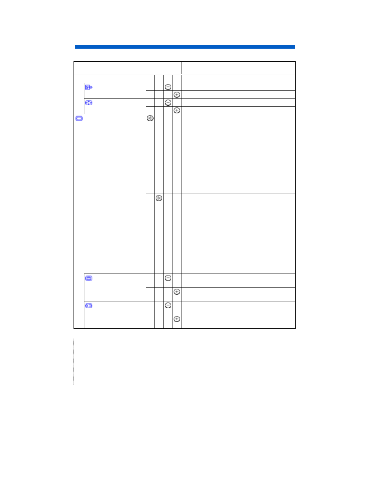
Table 1. Adjustment
Item Adjustment
BRIGHTNESS
CONTRAST
MAIN MENU
H. SIZE
H. POSITION
V. SIZE
V. POSITION
(To be continued on the next page.)
button
Function
makes brightness darker
including background.
makes brightness brighter
including background.
makes contrast darker excluding
background.
makes contrast brighter excluding
background.
changes to the previous mode.
H. SIZE ZOOM
OSD EXIT DEGAUSS DMS
COLOR MENU? COLOR SELECT
OSD MENU? RECALL MENU?
SCREEN MENU? ROTATION
PIN. BALANCE PARALLELOGRAM
PINCUSHION TRAPEZOID
V. POSITION V. SIZE
H. POSITION H. SIZE
changes to the next mode.
H. SIZE H. POSITION
V. SIZE V. POSITION
TRAPEZOID PINCUSHION
PARALLELOGRAM PIN. BALANCE
ROTATION SCREEN MENU?
RECALL MENU? OSD MENU?
COLOR SELECT COLOR MENU?
DMS DEGAUSS OSD EXIT
ZOOM H. SIZE
shrinks horizontally.
expands horizontally.
moves the position to the left.
moves the position to the right.
shrinks vertically.
expands vertically.
moves the position down.
moves the position up.
11
Page 13

OPERATION (Continued)
j
Table 1. Adjustment (Continued)
Item Ad
(MAIN MENU)
TRAPEZOID
PINCUSHION
PARALLELOGRAM
PIN. BALANCE
ROTATION
SCREEN MENU ?
RECALL MENU ?
OSD MENU ?
COLOR SELECT
COLOR MENU ?
DMS
DEGAUSS
(To be continued on the next page.)
ustment
button
Function
shrinks the top side, and expands the
bottom side.
expands the top side, and shrinks the
bottom side.
curves the left/right sides inward.
curves the left/right sides outwards.
tilt to the left.
tilt to the right.
curves the left/right sides to the left.
curves the left/right sides to the right.
rotates counter clockwise.
rotates clockwise.
(unavailable)
calls “SCREEN MENU”.
(unavailable)
calls “RECALL MENU”.
(unavailable)
calls “OSD MENU”.
changes the color to the previous mode.
DMSUSER500065009300DMS
changes the color to the next mode.
DMS930065005000USERDMS
(unavailable)
calls “COLOR MENU”.
cancels the DMS mode. (NO)
set the DMS mode. (YES)
It increases the brightness for dynamic
motion picture system.
(unavailable) (NO)
executes degaussing. (YES)
12
Page 14
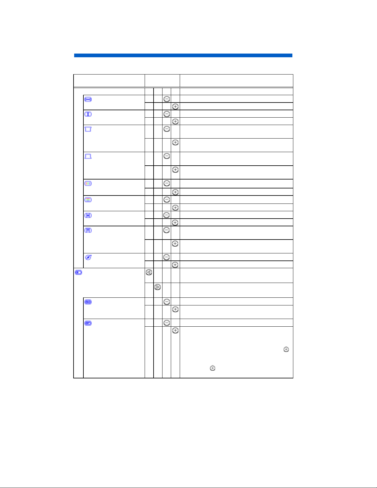
OPERATION (Continued)
j
Table 1. Adjustment (Continued)
Item Ad
(MAIN MENU)
OSD EXIT
ZOOM
SCREEN MENU
H. MOIRE
V. MOIRE
(To be continued on the next page.)
ustment
button
Function
(unavailable) (NO)
clears the OSD. (YES)
shrinks horizontally and vertically.
expands horizontally and vertically.
changes to the previous mode.
H. MOIRE HEMISPHERE
V. LIN. BALANCE
V. LINEARITY
V.CONV.
H.CONV.
BOTTOM CORNER
TOP CORNER
V. FOCUS
H. FOCUS
V. MOIRE H. MOIRE
changes to the next mode.
H. MOIRE V. MOIRE
H. FOCUS
V. FOCUS
TOP CORNER
BOTTOM CORNER
H.CONV.
V.CONV.
V. LINEARITY
V. LIN. BALANCE
HEMISPHERE H. MOIRE
makes the operation of the horizontal moire
changing circuit weaker.
makes the operation of the horizontal moire
changing circuit stronger.
makes the operation of the vertical moire
changing circuit weaker.
makes the operation of the vertical moire
changing circuit stronger.
NOTE:
* Moire may appear on the screen due to interference between CRT dot pitch and
video signal by conditions of video image, display size, display brightness, etc.
Adjust the conditions of display size, display brightness, etc., before the adjustment of
moire.
* In some cases, this function may cause deterioration of display quality, such as focus,
jitter, etc.
13
Page 15
OPERATION (Continued)
j
Table 1. Adjustment (Continued)
Item Ad
ustment
button
(SCREEN MENU)
H. FOCUS
V. FOCUS
TOP CORNER
BOTTOM CORNER
H.CONV.
V.CONV.
V. LINEARITY
V. LIN. BALANCE
HEMISPHERE
RECALL MENU
SINGLE RECALL
TOTAL RESET
(To be continued on the next page.)
Function
makes the horizontal dynamic focus weaker.
makes the horizontal dynamic focus stronger.
makes the vertical dynamic focus weaker.
makes the vertical dynamic focus stronger.
curves the left and right top corners
inwards.
curves the left and right top corners
outwards.
curves the left and right bottom corners
inwards.
curves the left and right bottom corners
outwards.
moves red to the left and blue to the right.
moves red to the right and blue to the left.
moves red down and blue up.
moves red up and blue down.
expands the top and the bottom vertically.
shrinks the top and the bottom vertically.
shrinks the top and expands the bottom
vertically.
expands the top and shrinks the bottom
vertically.
set the northern hemisphere mode. (N)
set the southern hemisphere mode. (S)
changes to the previous mode.
TOTAL RESET SINGLE RECALL
changes to the next mode.
SINGLE RECALL TOTAL RESET
(unavailable) (NO)
recalls the factory setting for the current
signal mode only. (YES)
(unavailable) (NO)
recalls all factory settings and delete the all
user settings. (YES)
To activate the TOTAL RESET command,
you will begin by pressing the button
At this time the OSD background will be red.
To apply the TOTAL RESET, simply press
the button
again and all user data will be
erased.
.
14
Page 16
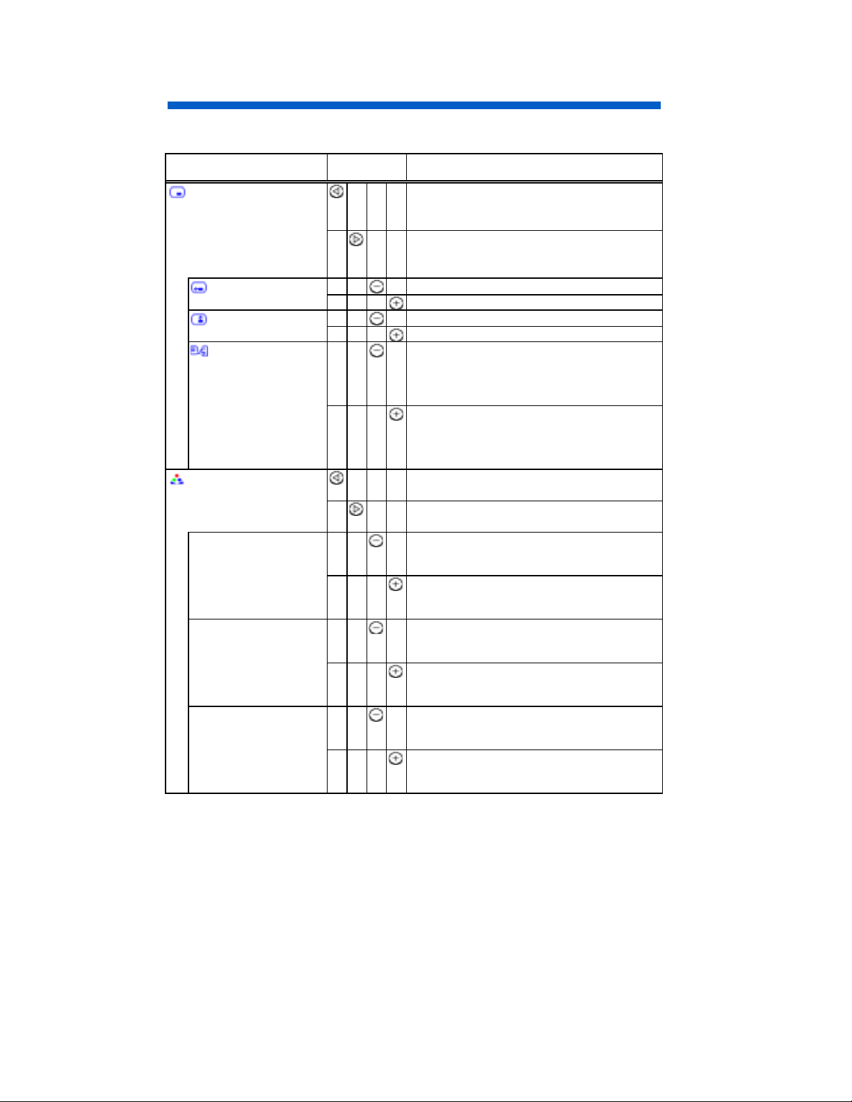
OPERATION (Continued)
Table 1. Adjustment (Continued)
Item Adjustment
Function
button
OSD MENU changes to the previous mode.
OSD H. POS. LANGUAGE SELECT
OSD V. POS. OSD H. POS.
changes to the next mode.
OSD H. POS. OSD V. POS.
LANGUAGE SELECT OSD H. POS.
OSD H. POS.
moves the OSD to the left.
moves the OSD to the right.
OSD V. POS.
moves the OSD down.
moves the OSD up.
LANGUAGE
SELECT
changes to the previous mode.
ENGLISH FRANÇAIS (French)
ITALIANO (Italian) ESPAÑOL (Spanish)
DEUTSCH (German) ENGLISH
changes to the next mode.
ENGLISH DEUTSCH (German)
ESPAÑOL (Spanish) ITALIANO (Italian)
FRANÇAIS (French) ENGLISH
COLOR MENU changes to the previous mode.
R B G R
changes to the next mode.
R G B R
R RED
makes the Green and Blue stronger.
When the Green or Blue reaches the upper
limit, it makes the Red weaker.
makes the Red stronger.
When the Red reaches the upper limit, it
makes the Green and Blue weaker.
G GREEN
makes the Blue and Red stronger.
When the Blue or Red reaches the upper
limit, it makes the Green weaker.
makes the Green stronger.
When the Green reaches the upper limit, it
makes the Blue and Red weaker.
B BLUE
makes the Red and Green stronger.
When the Red or Green reaches the upper
limit, it makes the Blue weaker.
makes the Blue stronger.
When the Blue reaches the upper limit, it
makes the Red and Green weaker.
15
Page 17
OPERATION (Continued)
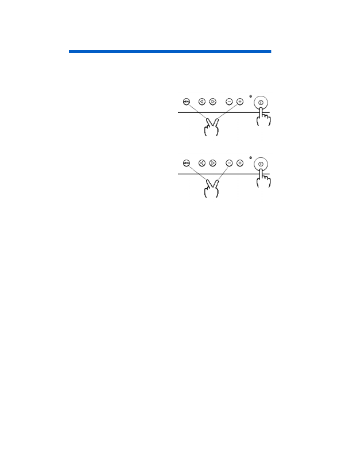
Lock out Function
There are two special LOCK OUT Functions:
1. Lock Out Function 1
Disables all of the user control buttons
except "Brightness/Contrast adjust”
and “Input Select button”
(1) Power Unit Off
(2) Depress two buttons
(3) Turn Power On.
2. Lock Out Function 2
Enable all buttons : Turns on all On
Screen Display functions
(1) Power Unit Off
(2) Depress two buttons
(3) Turn Power On.
:
:
16
Page 18
POWER SAVING SYSTEM
This monitor complies with VESA and
power saving system works only when used with VESA DPMS compliant PC’s and/or
graphic controllers.
NERGY STAR
E
®
power saving requirements. The
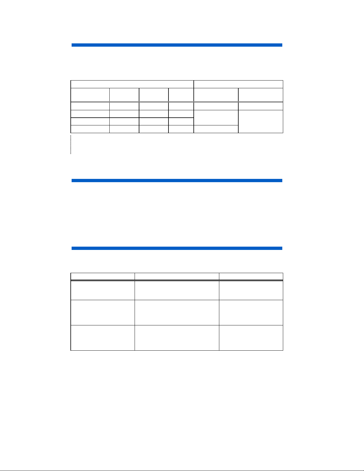
Table 2. Power Saving System
VESA DPMS Power Saving States
Power Saving
Mode
ON Active Yes Yes 115W (typical) Lighting Green
Stand-by Blanked No Yes Less than 10 W
Suspend Blanked Yes No Lighting Orange
Active OFF Blanked No No Less than 3 W
Video H. Sync. V. Sync. Power Power Indicator
NOTE:
* When to switch the power Off during the monitor is in Active OFF mode, sometimes the
power indicator lighting continues a few seconds. It is not failure.
PLUG & PLAY
This monitor complies with VESA DDC1/2B spe cifications. Plug & Play is a syste m, by
which computer, peripherals (including monitors), and operating system manufacturers
comply with for this user-friendly function. It works when the monitor is connected to
DDC ready computer that is running an operating system software that incorporates Plug
& Play functionality.
NOTE:
The Plug and Play function is only supported on INPUT1, and not supported on INPUT2.
SIGNAL CHECK
Your monitor is equipped with an automatic Signal Verification System. The Table 3
below outlines the operation of this system.
Table 3. Signal Check
Signal Condition Indication of OSD Power Indicator State
Proper signal is detected
by the monitor.
No Sync. Signal is detected
by the monitor.
A video signal is applied
to the monitor that is
beyond the monitor scan
range.
The OSD indicates the horizontal
frequency and vertical frequency
on the adjustment menu.
The OSD indicates the message
“POWER SAVE” for 5 seconds
after which time the unit will turn
into Power Saving Mode.
The OSD indicates the message
“INVALID SCAN FREQ.”.
17
The power indicator lights
green.
After 10 seconds, the
color of the power
indicator will turn to
orange.
The power indicator will
be illuminated as a solid
green color.
Page 19
TROUBLESHOOTING
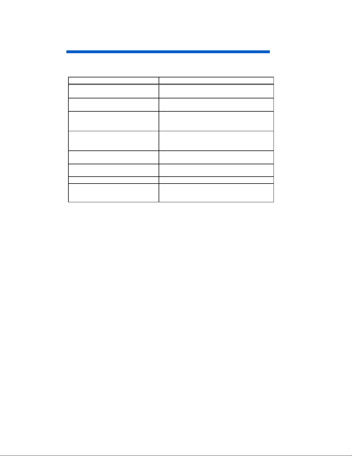
The following Table 4 is provided to assist you in common installation issues.
Table 4. Troubleshooting
Symptom Solution
No power Verify the power cord is installed correctly.
Press the power switch.
No picture Increase Contrast and Brightness.
Check Input Select status.
No picture and the power indicator
lights orange
“POWER SAVE” message appears Check Signal Cable Connection.
“INVALID SCAN FREQ.” message
appears
Wavy or elliptical (moire) pattern
appears
Color is not uniform Activate Degauss function.
Environmental influences Check to see that no magnetic appliance such
Check Signal Cable Connection.
Check Power Connection to computer.
Check Input Select status.
Check Power Connection to computer.
Check Input Select status.
Check Signal Cable Connection.
Check video input specification.
Adjust unit with moire control as outlined in the
Table 1-1.
as telephones, subwoofers/speakers, fans, or
florescent lighting are near the monitor.
18
Page 20

SPECIFICATIONS
CRT
21 inch type picture tube, 0.21 mm horizontal dot pitch, 0.20 mm horizontal mask pitch,
Invar shadow mask, Black matrix, Short persistence phosphors, Dark tint, Anti-Reflection
coat.
Input Signal
Video : 0.70 Vp-p, Analog
Sync. : Separate H/V, TTL level
Composite H/V, TTL level
Synchronisation
p1500 p1600
Horizontal : 31 - 107kHz 31 - 115 kHz
Vertical : 50 - 160 Hz 50 - 160 Hz
Resolution
Horizontal : up to 1856 dots up to 1920 dots
Vertical : up to 1392 lines up to 1440 lines
Viewable Image Size
Viewable Image Area
Horizontal : 406 mm (typical)
Vertical : 305 mm (typical)
Color Temperature
9300 : Standard color balance, 9300K
6500 : Standard color balance, 6500K
5000 : Standard color balance, 5000K
USER : User defined
DMS : Standard color balance, 9300K for the DMS mode
Power Supply
AC 100 - 120 / 200 - 240 V (auto select)
Power Consumption : 115 W (typical) (provided with power save circuit)
Warm-up Time
Dimensions
Weight
: 488 (W) x 482 (H) x 470 (D) mm
: 27.0 kg (approx.) (including Tilt & Swivel Base)
Heat Dissipation
Environmental Condition
Operating Temperature : 5 to 40 ºC
Operating Relative Humidity : 10 to 80 % without condensation
Storage Temperature : -20 to 60 ºC
Storage Relative Humidity : 10 to 90 % without condensation
: 21 inches (508 mm), diagonal (typical)
: 30 minutes to reach optimum performance level.
including Tilt & Swivel Base)
(
: 392BTU/Hr
19
Page 21
SPECIFICATIONS (Continued)
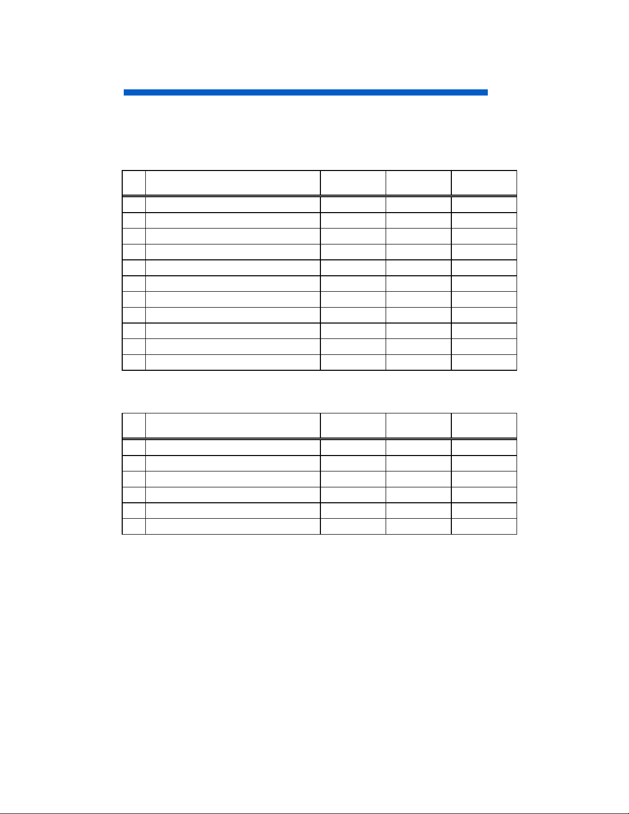
Standard Settings
Microprocessor-based preset functions can store 32 sets of geometry settings
incluexcept the standard settings. The following industrial standard settings have
been pre-programmed by the factory.
Table 5. Standard Settings
No. Video Mode Name
(with Resolution and Vertical Frequency)
1
VGA 640 480 - 60 Hz
2
VGA 720 400 - 70 Hz
3
VESA 800 600 - 85 Hz
4
VESA 1024 768 - 85 Hz
5
VESA 1280 1024 - 85 Hz
6
VESA 1600 1200 - 85 Hz
7
CPT 1600 1280 - 80 Hz
8
CPT 1600 1280 - 87 Hz
9
CPT 1600 1200 - 92 Hz
10
CPT 1856 1392 - 71 Hz
11
VESA 1920 1440 - 75 Hz
Horizontal
Frequency
31.47 kHz
31.47 kHz
53.67 kHz
68.68 kHz
91.15 kHz
106.25 kHz
106.25 kHz
114.90 kHz
114.90 kHz
102.77 kHz
112.50 kHz
p1500 p1600
The following industrial standard settings have been pre-loaded by the factory.
Table 6. Standard Settings (Pre-loaded)
No. Video Mode Name
(with Resolution and Vertical Frequency)
1
VESA 640 480 - 75 Hz
2
VESA 640 480 - 85 Hz
3
VESA 800 600 - 75 Hz
4
VESA 1024 768 - 75 Hz
5
VESA 1280 1024 - 75 Hz
6
VESA 1600 1200 - 75 Hz
Horizontal
Frequency
37.50 kHz
43.27 kHz
46.88 kHz
60.02 kHz
79.98 kHz
93.75 kHz
p1500 p1600
20
Page 22

SPECIFICATIONS (Continued)
NOTE:
* Input signals with approximately the same frequencies may be regarded as the same
signal.
* The following horizontal timing conditions are recommended (at sync. H, V separate
or H/V composite).
for 31 kHz - 55 kHz horizontal frequency:
Horizontal front porch should be more than 0.1 µs.
Horizontal sync. width should be within 1.0 - 3.8 µs.
Horizontal back porch should be more than 1.2 µs.
Horizontal blanking width should be more than 3.5 µs.
for 55 kHz – 115 kHz horizontal frequency:
Horizontal front porch should be more than 0.1 µs.
Horizontal sync. width should be within 0.8 - 3.0 µs.
Horizontal back porch should be more than 1.1 µs.
Horizontal blanking width should be more than 2.3 µs.
* The following vertical timing conditions are recommended.
Vertical front porch should be more than 10 µs.
Vertical sync. width should be less than 100 µs.
Vertical back porch should be more than 400 µs.
Vertical blanking width should be more than 450 µs.
* In case the front or back porch is extremely long, or the data display time is extremely
short, it may not be able to set the expected size and position.
21
Page 23
SPECIFICATIONS (Continued)
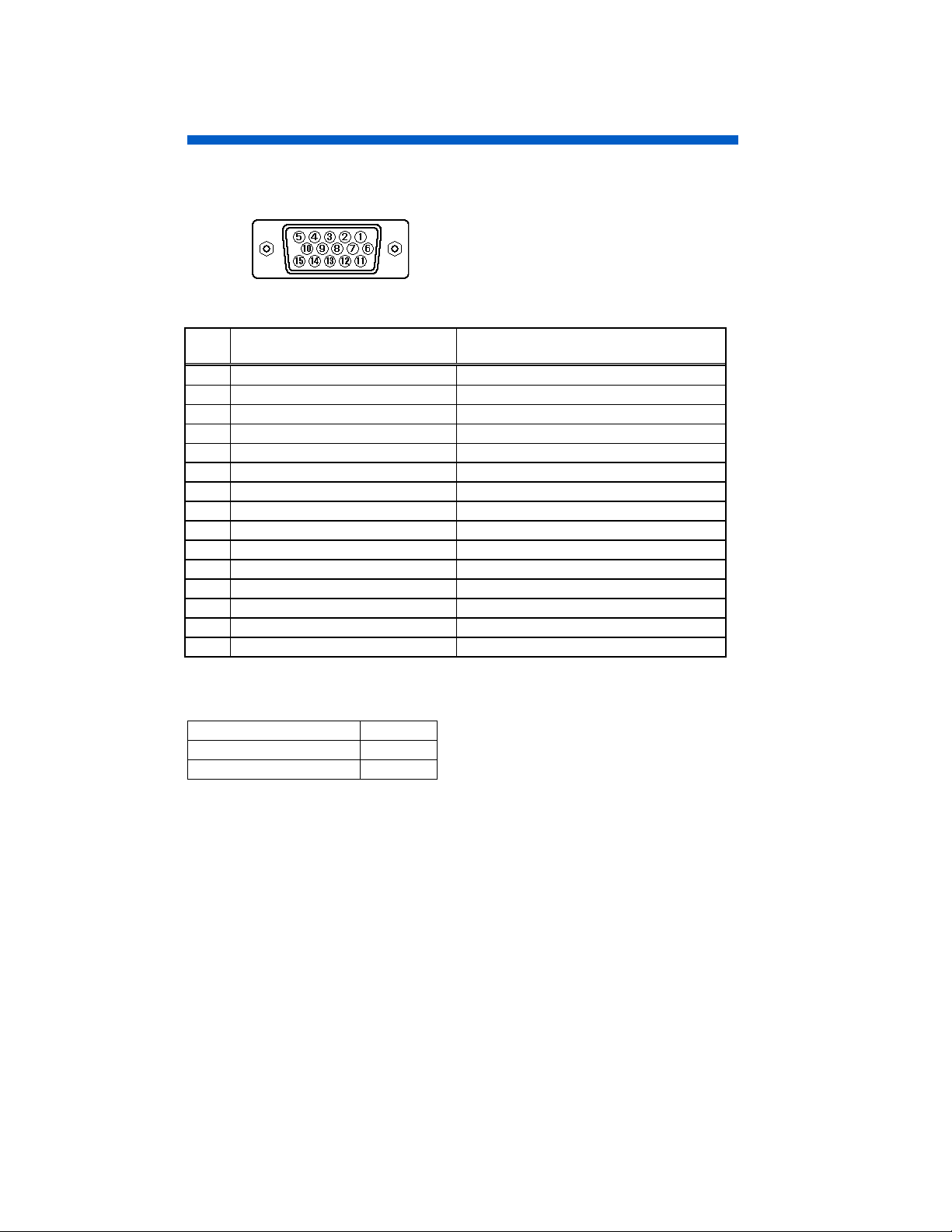
Pin Assignment
Signal Input Connector of the Monitor
Table 7. Pin Assignment
Pin
No.
Red Video Red Video
1
Green Video Green Video
2
Blue Video Blue Video
3
No pin No pin
4
No connection No connection
5
Red Ground Red Ground
6
Green Ground Green Ground
7
Blue Ground Blue Ground
8
No connection No connection
9
Ground Ground
10
No connection No connection
11
Bi-directional Data [SDA] No connection
12
H-Sync. (or H/V) H-Sync. (or H/V)
13
V-Sync. [VCLK] V-Sync.
14
Data Clock [SCL] No connection
15
Input 1 Input 2
If the graphics board supplies more than one type of sync. signal, the sync. signal type
will be automatically selected by the monitor, w ith the priority show n in the follow ing table.
Sync. Signal Type Priority
H, V Separate Sync. 1
H/V Composite Sync. 2
22
Page 24
CAUTIONS
ENGLISH
Discontinue Usage if Abnormal Operation Occurs !
Abnormal operations such as smoke, burning smell, excessive sound, etc. could cause
fire or electrical shock. If you observe any abnormal operation, you should turn Off the
monitor and disconnect the power plug from the power outlet. You should check for
smoke or fire and contact your dealer.
Do not expose the monitor to physical impact !
Do not allow foreign objects (water, metal, etc.) inside !
Never remove the cover !
The color monitor contains high voltage components. Ask your dealer to repair or clean
inside.
The power outlet should be close to the monitor and easily accessible !
Install the unit in an suitable environment !
Do not expose the monitor to rain, moisture, dust, corrosive gases, vibrations, etc. so as
to prevent electrical shock or fire hazard.
Avoid placing the monitor in direct sunlight or near heating appliances.
Do not place the monitor on an unstable base.
Keep in a well ventilated area !
Do not cover this monitor or place anything against any sides (not only the top, right and
left side but also the rear and bottom sides) of the monitor. Ventilation holes are
provided at all sides of covers to prevent excessive temperature increase.
Be cautious of magnetic fields !
DO NOT place a magnet, loudspeaker system, floppy disk drive, printer, or anything
which will generate magnetism near the unit. A magnetic field may cause blurred colors
or distortion of the displayed pattern.
Be mindful of the ambient illumination !
Avoid direct rays of the sun or room lighting onto the CRT screen in order to prevent eye
fatigue.
The enclosed power cord must be used !
Failure to do so may cause fire or electrical shock hazard.
Use only the correct voltage power outlet with safety ground connection !
This monitor will automatically adjust to the input voltage 100 - 120 / 200 - 240V.
Be cautious of the power cord connection !
Before inserting the plug of the power cord into a power outlet of the correct voltage,
check that the connection portion of the power cord is clean (with no dust). Then, insert
the plug of power cord into a power outlet firmly to avoid electrical shock or fire hazard.
Remove the power cord for complete separation !
For complete separation from the power source, remove the pow er cord from the monitor
or from the wall power outlet.
23
Page 25
CAUTIONS (Continued) ENGLISH
CAUTION for 200 - 240V operation only
This equipment relies on the protective devices in the building installation for short-circuit
and over-current protection. Refer to the following table for the suitable number and
location of the protective devices which should be provided in the building installation.
Informative examples of
protective devices in single - phase equipment or sub - assemblies
Protection
against
Case A: Equipment to be
connected to POWER SYSTEMS
with earthed neutral reliably
identified, except for Case C
below.
Case B: Equipment to be
connected to any supply,
including IT POWER SYSTEMS
and supplies with reversible
plugs, except for Case C below.
Case C: Equipment to be
connected to 3-wire power
systems with earthed neutral
reliably identified.
Verify that the protective devices in the building installation meets the conditions in the
table prior to installing the equipment.
Earth faults
Overcurrent
Earth faults
Overcurrent
Earth faults
Overcurrent
Minimum number
of fuses or circuit -
breaker poles
1
1
2
1
2
2
Location
Phase conductor
Either of the two
conductors
Both conductors
Either of the two
conductors
Each phase conductor
Each phase conductor
Be careful of static electricity on CRT surface !
To prevent electrical shock by the static electricity on the CRT surface, disconnect the
power cord at least 30 seconds after turning OFF the power.
Avoid frequent power ON-OFF switching !
Do not repeat OFF and ON power switching in a short period. This may cause blurred
colors or distortion of the displayed pattern.
Be careful of generated magnetism !
After the power has been turned ON or when the degauss function has been manually
engaged, the CRT is demagnetised for approximately 7 seconds. This generates a
strong magnetic field around the front cover which may affect the data stored on
magnetic tape or disks near the front cover. Place such magnetic recording equipment
and tapes/disks away from this unit.
About cleaning
Before cleaning, turn OFF the power switch and disconnect the plug from the power outlet.
For the screen, use water with a lightly moistened soft cloth such as a gauze type material.
For the cover, use water or a liquid synthetic detergent, with a lightly moistened soft cloth.
Do not clean the inside of monitor by yourself as it is very dangerous. Refer to your dealer.
Do not use aerosol sprays, solvents or abrasive cleaners.
24
Page 26
CAUTIONS (Continued) ENGLISH
FCC Statement Warning
WARNING
Class B digital device, pursuant to Part 15 of the FCC Rules. These limits are designed
to provide reasonable protection against harmful interference in a residential installation.
This equipment generates, uses, and can radiate radio frequency energy and, if not
installed and used in accordance with the instructions, may cause harmful interference to
radio communications. However, there is no guarantee that interference will not occur in
a particular installation. If this equipment does cause harmful interference to radio or
television reception, which can be determined by turning the equipment off and on, the
user is encouraged to try to correct the interference by one or more of the following
measures:
- Reorient or relocate the receiving antenna.
- Increase the separation between the equipment and receiver.
- Connect the equipment into an outlet on a circuit different from that to which the receiver
is connected.
- Consult the dealer or an experienced radio / TV technician for help.
INSTRUCTIONS TO USERS
(Federal Communication Commission) equipments provided that following conditions are met.
Video inputs: The input signal amplitude must not exceed the specified level.
CAUTION
compliance could void the user’s authority to operate the equipment.
We:
Located at:
: This equipment has been tested and found to comply with the limits for a
: This equipment complies with the requirements of FCC
: Changes or modifications not expressly approved by the party responsible for
Declaration of Conformity
Class B Personal Computers and Peripherals;
According to 47CFR, Part 2 and 15 f or
CPU Boards and Power Supplies used with Cl ass B P ersonal Computers:
Cornerstone
225 Hammond Avenue, Fremont CA 94539 U.S.A.
and / or
Declare under sole responsibility that t he product ident ified herein, com plies with 47CFR Part 2
and 15 of the FCC rules as a Class B digi tal devic e. Eac h product mark eted, is ident ical t o the
representative unit tes ted and found to be compliant with the standards. Records maintained
continue to reflect t he equipment being produced can be expected to be within the variation
accepted, due to quantity production and testing on a stat i stical basis as requi red by 47CFR §
2.909. Operation is subject to the following two conditions: (1) This device may not cause
harmful interference, and (2) This device must accept any interference received, including
interference that may cause undes ired operation. The above named party is responsible f or
ensuring that the equipment complies with the standards of 47CFR § § 15.101 to 15.109.
Trade name:
Model Number:
Signature of Party Responsible:
Printed name of Party Responsible:
Color Monitor
DJ82
James W.Witkowski
Executed on (Date), at (Place):
February 20, 2001, CA., U.S.A.
For the Customers in CANADA
NOTICE
: This Class B digital apparatus complies with Canadian ICES-003.
25
Page 27
CAUTIONS (Continued) ENGLISH
For the Customers in the UK
THIS PRODUCT IS SUPPLIED WITH A TW O PIN MAINS PLUG FOR USE IN MAINLAND
EUROPE. FOR THE UK PLEASE REFER TO THE NOTES ON THIS PAGE.
IMPORTANT FOR UNITED KINGDOM
WORDING FOR CLASS
The mains lead on this equipment is supplied with a moulded plug incorporating a fuse,
the value of which is indicated on the pin face of the plug. Should the fuse need to be
replaced, an ASTA or BSI approved BS 1362 fuse must be used of the same rating. If
the fuse cover is detachable never use the plug with the cover omitted. If a replacement
fuse cover is required, ensure it is of the same colour as that v isible on the pin face of the
plug. Fuse covers are available from your dealer.
DO NOT cut off the mains plug from this equipment. If the plug fitted is not suitable for
the power outlets in your home or the cable is too short to reach a power outlet, then
obtain an appropriate safety approved extension lead or consult your dealer.
Should it be necessary to change the mains plugs, this must be carried out by a
competent person, preferably a qualified electrician.
If there is no alternative to cutting off the mains plug, ensure that you dispose of it
immediately, having first removed the fuse, to avoid a possible shock hazard by
inadvertent connection to the mains supply.
WARNING: THIS EQUIPMENT MUST BE EARTHED
IMPORTANT
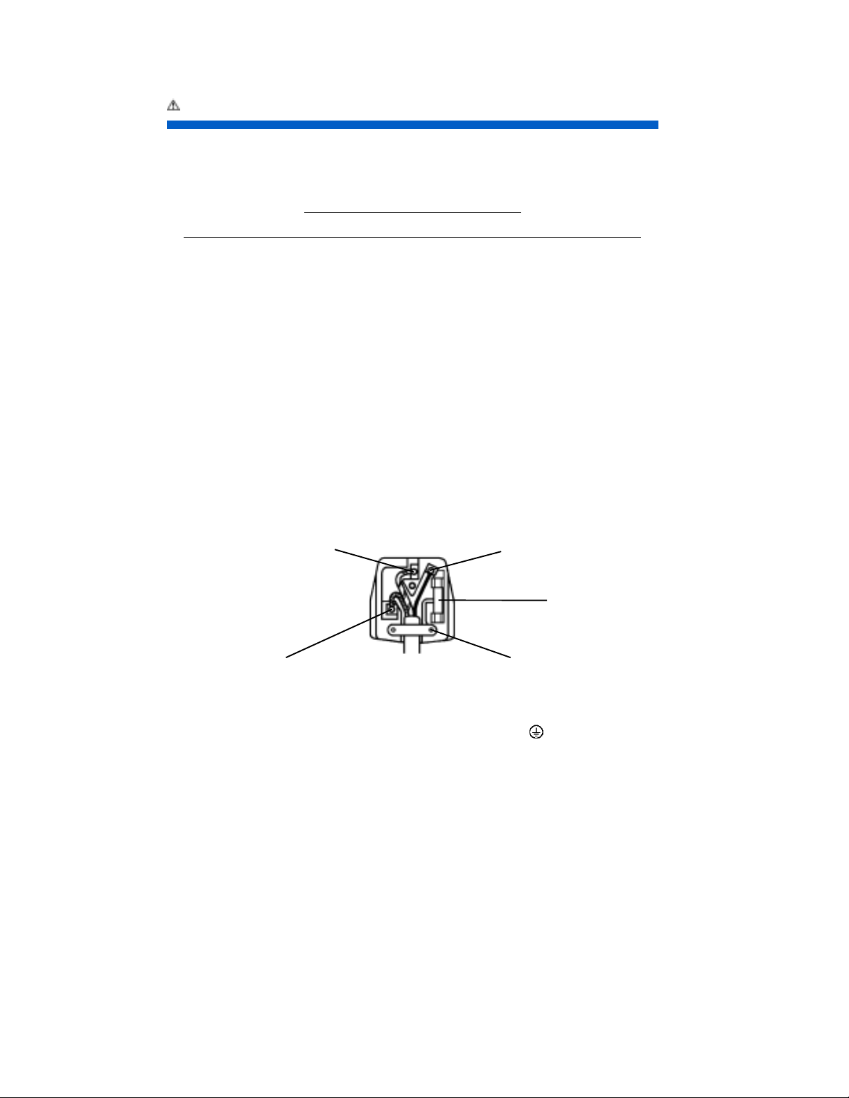
The wires in the mains lead are coloured in accordance with the following code:
Green and Yellow = Earth, Blue = Neutral, Brown = Live.
Green & Yellow to Earth Brown to Live
EQUIPMENT INSTRUCTION BOOKS AND LABELS
Fuse
Blue to Neutral Cord Clamp
As these colours may not correspond with the coloured markings identify ing the terminals
in your plug, proceed as follows:
The wire which is coloured GREEN and YELLOW must be connected to the terminal in
the plug which is marked with the letter E or by the earth symbol
or GREEN and YELLOW.
The wire coloured BLUE must be connected to the terminal marked with the letter N or
coloured BLUE or BLACK. The wire coloured BROWN must be connected to the
terminal marked with the letter L or coloured BROWN or RED.
26
or coloured GREEN
Page 28
PRÉCAUTIONS
FRANÇAIS
Cessez l'utilisation du module si un incident se produit !
Un incident tel que fumée, odeur de brûlé, bruit excessif, etc. pourrait causer un feu ou un
choc électrique. Si vous constatez un incident, éteignez le moniteur et débranchez le
câble d'alimentation de la prise du secteur. Vérifiez alors s'il y a du feu ou de la fumée et
contactez votre revendeur.
Evitez tout choc au moniteur !
Ne laissez pas de corps étrangers (eau, métal, etc.) pénétrer à l’intérieur !
Ne retirez jamais le couvercle !
Ce moniteur couleur contient des composants de tension élevée. Contactez votre
revendeur pour toute réparation et tout nettoyage de l'intérieur.
La prise secteur doit être proche du moniteur et facilement accessible !
Installez le moniteur dans un environnement adéquat !
N’exposez pas le moniteur à la pluie, l'humidité, la poussière, les gaz corrosifs, les
vibrations, etc. afin d’éviter tout risque d'électrocution ou d’incendie.
Ne placez pas le moniteur sous le rayonnement direct du soleil ou près d’appareils de
chauffage.
Evitez de placer le moniteur sur une surface instable.
Placez le moniteur dans un endroit bien ventilé !
Ne couvrez pas le moniteur et ne placez aucun objet contre l’une quelconque de ses
surfaces (que ce soit au-dessus, à droite, à gauche, à l’arrière ou sous le moniteur).
Des orifices de ventilation sont placés sur tous les côtés du coffret afin d’éviter toute
élévation de température.
Attention aux champs magnétiques !
Ne placez pas d’aimant, de système de haut-parleur, de lecteur de disquettes,
d’imprimante, ou d’appareil capable de générer un champ magnétique auprès du
moniteur. Un champ magnétique peut brouiller les couleurs ou provoquer la distorsion
de l’affichage.
Attention à l'Eclairage ambiant !
Afin de réduire la fatigue oculaire, évitez le rayonnement direct du soleil ou de l’éclairage
de la pièce sur l’écran.
Utiliser le cordon d’alimentation fourni avec le moniteur !
Le non-respect de ces normes, peut entraîner des électrocution ou risque d’incendie.
Utilisez uniquement des prises de tension appropriée et reliées à la terre !
Ce moniteur se règle automatiquement sur la tension d’entrée 100 - 120 / 200 - 240 V.
Faites attention au branchement du cordon d’a limentation !
Avant de brancher la prise mâle du cordon d’alimentation sur une prise murale de tension
correcte, vérifiez que la partie de ce cordon qui se trouve au niveau de la connexion est propre
(c’est-à-dire qu’il n’y a pas de poussière). Ensuite, enfoncez fermement la prise mâle de ce
cordon dans une prise murale afin d’éviter tout risque de choc électrique ou d’incendie.
Pour une isolation complète, retirez le cordon d’alimentation !
Pour une isolation complète par rapport à la source d’alimentation, retirez le cordon
d’alimentation du moniteur ou de la prise murale.
27
Page 29
PRÉCAUTIONS (Suite)
FRANÇAIS
ATTENTION uniquement destiné à l’utilisation en 200 - 240 V
Cet équipement utilise les systèmes de protection électriques du bâtiment où il est
installé pour l’isolation contre les courts-circuits ou les surtensions. Voir le tableau qui
suit pour la localisation et le nombre adéquats de systèmes de protection du bâtiment.
Exemples informatifs de
dispositifs de protection dans les matériels et sous-ensembles monophasés
Protection
contre
Cas A: Matériel destiné à être
relié uniquement à des SCHÉMAS
D’ALIMENTATION avec neutre
à la terre identifié de façon sûre
excepté pour le cas C ci-dessous.
Cas B: Matériel destiné à être
relié à toute alimentation, y compris
les SCHÉMAS D’ALIMENTATION
IT et les alimentations avec
fiches réversibles excepté pour
le cas C ci-dessous.
Cas C: Matériel destiné à être
relié à des schémas d’alimentation
3 conducteurs avec neutre à la
terre identifié de façon sûre.
Vérifiez que les systèmes de protection du bâtiment correspondent aux conditions
indiquées dans ce tableau avant d’installer le moniteur.
Défaut à la
terre
Surintensité
Défaut à la
terre
Surintensité
Défaut à la
terre
Surintensité
Nombre minimal de
coupe-circuit à
fusibles ou de pôles
de disjoncteur
1
1
2
1
2
2
Emplacement
Conducteur de
phase
L’un ou l’autre des
conducteurs
Deux conducteurs
L’un ou l’autre des
conducteurs
Chaque conducteur
de phase
Chaque conducteur
de phase
Attention a l’électricité statique présente à la surface de l’écran !
Pour éviter tout risque d’électrocution due à l’électricité statique présente à la surface de
l’écran, débranchez le cordon d’alimentation au moins 30 secondes après avoir éteint le
moniteur.
Evitez’allumer et d’éteindre le moniteur à intervalles trop rapprochés !
N’allumez pas et n’éteignez pas le moniteur à des intervalles trop rapprochés. Vous
risquez de brouiller les couleurs ou la détérioration de l’affichage.
Attention au magnétisme !
Lorsque le moniteur est mis sous tension ou démagnétisé, l’écran est démagnétisé
pendant environ 7 secondes. Cette opération génère un champ magnétique important
autour du carter avant qui peut affecter les données stockées sur des bandes ou des
disques magnétiques proches. Placez les appareils d’enregistrement m agnétiques ainsi
que les bandes et les disquettes, à l’écart de ce moniteur.
28
Page 30

PRÉCAUTIONS (Suite)
FRANÇAIS
À propos de l’entretien
Avant tout nettoyage, éteignez le moniteur et débranchez-le de sa prise de courant.
Pour le capot, utilisez de l’eau ou un détergent synthétique léger avec un tissu doux ou
de la gaze.
Pour l’écran, utilisez de l’eau avec un tissu doux ou de la gaze, délicatement.
Ne nettoyez pas vous-même l’intérieur du moniteur, pour cause de grave danger.
Consultez votre détaillant.
N’utilisez pas de vaporisateurs, de solvants ou de nettoyants abrasifs.
Pour les utilisateurs au Canada
AVIS
: Cet appareil numérique de la Classe B est conforme à la norme NMB-003 du
Canada.
29
Page 31
SICHERHEITSMASSNAHMEN
DEUTSCH
Betrieb des Gerätes einstellen, wenn anormale Bedingungen eintreten !
Anormale Bedingungen wie Rauch-Entwicklung, Brand-Geruch, übermäßige GeräuschEntwicklung usw. können zu Feuer und elektrischen Schlägen führen. Wenn Sie anormale
Bedingungen beobachten, sollten Sie den Monitor ausschalten und das Stromkabel aus der
Steckdose ziehen. Sie sollten prüfen, ob Rauch- oder Feuerentwicklung vorliegt und sich
mit Ihrem Fachhändler in Verbindung setzen.
Setzuen Sie den Monitor keinen Erschütterungen aus !
Lassen Sie keine Gegenstände oder Flüssigkeiten in das Gerät gelangen !
Entfernen Sie niemals das Gehäuse !
Der Monitor enthält Hochspannungskomponenten. Falls erforderlich, bitten Sie Ihren
Händler den Monitor zu reparieren oder von innen zu reinigen.
Die Steckdose sollte sich in der Nähe des Monitors befinden und leicht
zugänglich sein !
Installieren Sie den Monitor an einem geeigneten Standort !
Um Brand- und Elektroschock-Gefahr zu vermeiden, setzen Sie den Monitor keinen
Einfüssen wie REGEN, FEUCHTIGKEIT, STAUB, KORROSIVEN GASEN, VIBRATIONEN,
etc. aus. Achten Sie darauf, den Monitor nicht in direktem Sonnenlicht oder in der Nähe
eines Heizkörpers aufzustellen.
Stellen Sie den Monitor nicht auf einer instabilen Unterlage auf.
Verwenden Sie das Gerät nur an gut belüfteten Standorten !
Decken Sie den Monitor nicht ab bzw. halten Sie alle Seitenflächen frei von
Gegenständen (beide Seitenflächen wie auch die Ober- und Rückseite des Monitors).
Auf der Rückseite des Monitorgehäuses sind an allen Seiten Belüftungsöffnungen
angebracht, um ein Ansteigen der Innentemperatur zu verhindem.
Achten Sie auf Magnetfelder !
Stellen Sie niemals Magnete, Lautsprecher, Diskettenlaufwerke oder andere Geräte, die
Magnetfelder erzeugen, in der Nähe des Monitors auf. Magnetfelder können zu
Farbfehlern und Verzerrungen führen.
Sorgen Sie für eine geeignete Umgebungsbeleuchtung !
Vermeiden Sie eine direkte Sonneneinstrahlung bzw. die direkte Bestrahlung des
Bildshirms mit einer Lichtquelle, um eine Ermüdung der Augen zu vermeiden.
Verwenden Sie ausschließlich das mitgelieferte Netzanschlußkabel !
Anderenfalls können Brände oder elektrische Schläge verursacht werden.
Verwenden Sie den Monitor ausschließlich an Steckdosen mit der geeigneten
Spannung und Sicherheitserdung !
Dieser Monitor paßt sich automatisch an die Eingangsspannung 100 - 120 / 200 - 240V an.
Vorsicht beim Umgang mit dem Netzanschlusskabel !
Bevor Sie den Stecker des Netzanschlußkabels in eine Steckdose mit der geeigneten
Spannung einstecken, vergewissern Sie sich, daß der Stecker des N etzanschlußabels sauber
ist (staubfrei). Stecken Sie anschließend den Stecker des Netzanschlußkabels fest in eine
Steckdose, da anderenfalls elektrische Schläge oder Brand augelöst werden können.
30
Page 32
SICHERHEITSMASSNAHMEN (For ts.)
g
g
g
Entfernen Sie das Netzanschlußkabel, um den Monitor komplett vom
DEUTSCH
Stromkreis zu tr ennen !
Um eine komplette Tremmung von der Stromquelle zu erreichen, entfemen Sie das
Netzanschlußkabel vom Monitor oder ziehen es aus der Steckdose.
Hinweis ausschließlich für den Betrieb mit 200 - 240V:
Für den Betrieb des Geräts muß sichergestellt sein, daß Schutzeinrichtungen gegen
Kurzschluß und Überlaststrom im Gebäude, in dem der Monitor installiert wird, vorhanden
sind. Aus der folgenden Tabelle können Sie die geeignete Anzahl und Anbringung der
Schutzeirurichtungen entnehmen, die im Gebäude installiert sein sollten:
Beispiele für Schutzeinrichtungen in Einphasengeräten oder Baugruppe
Schutz gegen Mindestanzahl der
Fall A: Gerät wird an STROMVERSORGUNG mit zuverlässi
identifizierbarem Null - Leiter
angeschlossen, ausgenommen
Fall C, s. unten.
Fall B: Gerät wird an beliebiger
Stromquelle, einschließlich
IT-STROMVERSORUNG und
Stromversorgungen mit Zweiwe
steckern, angeschlossen,
ausgenommen Fall C, s. unten.
Fall C: Gerät wird an 3-phasige
Stromversorgung mit zuverlä ssi
identifizierbarem Null - Leiter
angeschlossen
Kontrollieren Sie vor der Installation des Gerätes, ob die Schutzvorrichtungen in der
Gebäudeinstallation die Bedingungen aus der Tabelle erfüllen.
Erdungsfehler
Überstrom
Erdungsfehler
Überstrom
Erdungsfehler
Überstrom
Sicherungen oder
Schutzschalter
1
1
2
1
2
2
Anschluß
Phasenleiter
Einer der beiden
Leiter
Beide Leiter
Einer der beiden
Leiter
Jeder Phasenleiter
Jeder Phasenleiter
Statische Elektrizität auf der Bildschirmoberfläche !
Um einen elektrischen Schlag durch die statische Elektrizität auf der Bildschirmoberfläche
zu vermeiden, das Netzkabel frühestens 30 Sekunden nach dem Ausschalten lösen.
Häufiges aus- und einschalten des Monitors vermeiden !
Niemals den Netzschalter in kurzen Abständen betätigen. Andernfalls können
Farbfehler und Verzerrungen der angezeigten Bilder auftreten.
Vom Monitor erzeugte Magnetfeldern.
Nach dem Einschalten des Gerätes oder nach dem manuellen Aktivieren der DegaussFunktion wird die Bildröhre für die Dauer von etwa 7 Sekunden entmagnetisiert. Dabei
entsteht ein starkes Magnetfeld in der Umgebung des Monitorgehäuses. Dieses
Magnetfeld kann die Daten auf Magnetbändern und Disketten in unmittelbarer Nähe des
Monitors beeinflussen. Plazieren Sie daher magnetische Aufzeichnungsgeräte,
Bänder und Disketten nicht in unmittelbarer Nähe des Monitors.
31
Page 33

SICHERHEITSMASSNAHMEN (For ts.)
DEUTSCH
Reinigung
Bevor Sie mit der Reinigung beginnen, schalten Sie den Monitor aus und ziehen Sie den
Netzstecker.
Zum Renigen des Gehäuses verwenden Sie einen gazeartigen, weichen Lappen mit
Wasser oder einer in Wasser verdünnten Waschlauge ohne Seife.
Zum Reinigen des Bildschirms verwenden Sie einen gazeartigen, weichen Lappen mit
Wasser. Nur leicht über das Bildröhre wischen.
Reinigen Sie das innere des Monitor nicht selbst, sondern wenden Sie sich hierfür an
Ihren Händler.
Verwenden Sie weder Treibgashaltige Sprays noch Lösungs- oder Scheuermittel.
Ergonomie
Um den Anforderungen der deutschen Ergonomie-Norm ZH1/618 zu entsprechen,
1. wird empfohlen, die Grundfarbe Blau nicht auf dunklem Hintergrund zu verwenden
(schlechte Erkennbarkeit, Augenbelastung bei zu geringem Zeichenkontrast),
2. wird folgende Einstellung des Grafikcontrollers und Monitors empfohlen:
* Vertikalfrequenz : 85 Hz oder höher,
* Ohne Zeilensprung
32
Page 34
PRECAUCIONES
ESPAÑOL
Finalice su utilización en caso de funcionamiento anormal !
En caso de un funcionamiento anormal como humo, olor a quemado, zumbidos, etc,
podría aparecer fuego o descargas eléctricas. Si observa alguna anomalía, apague
rápidamente su monitor y desconecte el cable de alimentación de la red. Acuda a su
distribuidor.
Evite los golpes o impactos contra el monitor !
No permita que penetren objetos en el interior de la unidad (agua, metal,
etc.) !
Nunca extraiga la carcasa del monitor !
El monitor contiene componentes de alto voltaje. Consulte a su distribuidor si quiere
reparar o limpiar el interior del monitor.
Asegúrese que la toma de corriente esté situada cerca del monitor, y
sea accesible fácilmente !
Instale el monitor en un lugar adecuado !
Nunca exponga el monitor a lluvia, humedad, suciedad, gases corrosivos, vibraciones,
etc para evitar fuego o descargas eléctricas.
Evite exponer el monitor a luz solar directa, o cerca de fuentes de calor.
Nunca sitúe el monitor en un lugar inestable.
Sitúe el monitor en un lugar bien ventilado !
Nunca cubra el monitor ni coloque nada contra los lados de la unidad (no únicamente en
la parte superior y en los lados derecho e izquierdo, tampoco en laspartes posterior e
inferior de la unidad). Las ranuras de ventilación de la parte posterior sirven para evitar
que aumente la temperatura en el interior de la unidad.
Tenga cuidado con los campos magnéticos !
No coloque cerca de la unidad imanes, sistemas de altavoces, unidades de discos
flexibles, impresoras o cualquier otro dispositivo que pueda generar campos magnéticos.
Un campo magnético puede producir colores borrosos o distorsión de las imágenes
presentadas.
Cuidado con la iluminación ambiente !
Evite que los rayos solares o luz artificial incidan directamente sobre la pantalla, para
evitar la fatiga visual.
Debe utilizar el cable de alimentación suministrado !
Sinó pueden aparecer descargas eléctricas o fuego.
Para alimentar el monitor utilice un toma de corriente con cone xión de tierra !
Este monitor se ajusta automáticamente en función del voltaje de entrada 100 - 120 /
200 - 240V.
Cuidado con las conexiones de los cables de alimentación !
Compruebe que el conector de alimentación está libre de suciedad antes de insertarlo en
el conector de alimentación del monitor. Entonces, conecte el cable de alimentación
firmemente para evitar descargas eléctricas o fuego.
Retire el cable de alimentación para desmontar el monitor !
Para desmontar el monitor desconecte el cable de alimentación del monitor y de la red.
33
Page 35
PRECAUCIONES
Continuación
ESPAÑOL
Precaución para funcionamiento 200 - 240V
Para mayor seguridad compruebe que esta unidad va a ser utilizada en un edificio que
disponga de dispositivos de protección contra cortocircuitos y sobrecorrientes. Consulte
la siguiente tabla para comprobar el número y el tipo de dispositivos de protección
necesarios.
Ejemplos informativos de
dispositivos de proteccion en equipos monofasicos
Protección
contra:
Caso A: Equipamiento para conectar
a SISTEMAS DE ALIMENTACIÓN
con neutro identificado, excepto
caso C.
Caso B: Equipamiento para conectar
en cualquier suministrador, incluyendo
SISTEMAS DE ALIMENTACION IT,
y con conectores reversibles, excepto
Caso C.
Caso C: Equipamiento para conectar
a sistemas de alimentación trifásicos
con neutro identificado.
Verifique que los dispositivos de protección en las instalaciones de los edificios, cumplen
las condiciones expuestas en la tabla, antes de instalar el monitor.
Fallos de tierra
Sobre-corriente
Fallos de tierra
Sobre-corrient
Fallos de tierra
Sobre-corrient
Mínimo número
de fusibles
1
1
2
1
2
2
Situación
Fase
Cualquiera de los
dos conductores
Ambos
conductores
Cualquiera de los
dos conductores
A cada conductor
A cada conductor
Tenga cuidado con la electricidad estática de la superficie del TRC !
Para evitar descargas eléctricas debidas a la corriente estática de la superficie del TRC,
desconecte la alimentación de la unidad al menos 30 segundos después de apagar la
unidad.
Evite las conexiones y desconexiones frecuentes de la alimentación !
No repita la conexión y desconexión en un corto periodo de tiempo. Podría causar
colores borrosos o distorsión de las imágenes visualizadas.
Cuidado con los campos magnéticos generados !
Después de conectar la alimentación o de pulsar el botón de desmagnetizar, el TRC se
desmagnetiza durante aproximadamente 7 segundos. Esto genera un fuerte campo
magnético alrededor que puede afectar datos almacenados en cintas o discos
magnéticos que estén en su proximidad. Coloque éstos sistemas de almacenamiento
magnético alejados de esta unidad.
Limpieza del monitor
Antes de proceder a su limpieza, apague el monitor y desconéctelo de la red.
Para limpiar la superficie del monitor utilice agua o agua con jabón con un paño suave, y
para la pantalla, utilice agua con un paño suave como una gasa.
No limpie el interior del monitor, es muy peligroso. Para ello acuda a su suministrador.
No utilice sprays con aerosoles, disolventes o limpiadores abrasivos.
34
Page 36
PRECAUZIONI
ITALIANO
Sconnetere il monitor in caso di Malfunzionamenti Gravi !
Malfuzionamenti Gravi quali fumo, odore di bruciato, rumorosità eccesive etc. sono
sintomi di corto circuiti elettrici con possibilita’ di sviluppo d’incendio. In presenza di
questi tipi di Malfunzionamento, spegnete immediatamente il Monitor e togliete la spina
del cavo di alimentazione dalla presa di corrente. Controllate che il fumo o l’eventuale
insorgere del fuoco sia cessato, quindi contattate con urgenza il centro di assistenza
HITACHI.
Evitare di urtare il monitor !
Evitare l’ingresso di oggetti estranei (acqua, metallo, ecc.) nel monitor !
Non rimuovere mai il pannello !
Il monitor contiene componenti ad alto voltaggio. Qualora si desideri effettuare la pulizia
interna o si renda necessaria la riparazione, rivolgersi al proprio rivenditore.
La presa di corrente dovrebbe t rovarsi il più possible v icino al mo nitor
ed essere facilmente accessible !
Installare il monitor in ambiente adeguato !
Non esporre il monitor alla pioggia, umido, polvere, gas corrosivi, vibrazioni, ecc.
Evitare di posizionare il monitor alla luce diretta del sole o in prossimità di sorgenti di calore.
Non posizionare il monitor su un piano instabile.
Tenere in un posto ben ventilato !
Non coprire questo monitor o poggiare qualcosa contro qualunque dei suoi lati (non solo sopra,
a destra e sinistra ma anche sui lati inferiore e posteriore). Delle aperture di ventilazione sono
praticate su tutti i lati del coperchio per prevenire surriscaldamenti.
Fate attenzione ai campi magnetici !
Non tenere un magnete, altoparlanti, lettori di floppy disk, stampanti o qualsiasi oggetto
che possa generare magnetismo vicino al Monitor. Il campo magnetico può creare
macchie di colore o distorsioni di vario genere.
Curare l’illuminazione dell’ ambiente !
Evitare che I raggi del sole o dell’ illuminazione della stanza colpiscano direttamente lo
schermo al fine di prevenire l’affaticamento visivo.
Utilizzare soltanto il cavo di alimentazione fornito !
Non ottemperando a ciò, può manifestarsi il rischio di incendio o di shock elettrico.
Utilizzare soltanto una presa di corrente con il corretto voltaggio e
dotata di collegamento a terra !
Questo monitor è in grado di regolarsi automaticamente sul voltaggio in ingresso 100 120 / 200 - 240V.
Attenzione alla connessione del cavo di alimentazione !
Prima di inserire la spina del cavo di alimentazione nella presa con il corretto voltaggio,
verificare che i contatti elettrici del cavo stesso siano puliti (priv i di polv ere). Poi, inserire
saldamente la spina del cavo nella presa, altrimenti potrebbe dar luogo ad incendio o
shock elettrico.
Rimuovere il cavo di alimentazione per il distacco totale !
Per un distacco totale dalla rete elettrica, rimuovere il cavo di alimentazione dalla presa di
corrente o dal monitor.
35
Page 37
PRECAUZIONI
Continua
ITALIANO
Attenzione (per funzionamento soltanto a 200 - 240V)
Questo apparecchio fa affidamento su dispositivi di protezione localizzati negli impianti
degli edifici, contro corto-circuito o sovracorrente. Riferirsi alla seguente tabella per
l’idoneo numero e locazione di questi dispositivi di protezione.
Dispositivi di protezione per apparecchiature monofase o sottoassemblate
Caso A: Apparecchiatura da
connettersi a SISTEMI DI POTENZA
dotati di presa di terra ben
identificabile, eccetto per il caso C
sotto.
Caso B: Apparecchiatura da
connettersi a qualunque alimentazione, compresi SISTEMI DI POTENZA
e alimentazioni con spine reversibili,
eccetto per il caso C sotto.
Caso C: Apparecchiatura da
connettersi al sistema dotato di
cavo alimentazione a 3 fili dotato
di presa di terra ben identificabile.
Verificare che i dispositivi di protezione nell’impianto dell’edificio rispondano alle
condizioni in tabella prima di installare l’apparecchiatura.
Esempi informativi di
Protezione Minimo numero di
fusibili o di inter-
ruttori automatici
Verso terra
Sovracorrente
Verso terra
Sovracorrente
Verso terra
Sovracorrente
Locazione
1
1
2
1
2
2
Conduttore di fase
Qualunque dei
due singoli
conduttori
Ambo i conduttori
Qualunque dei
due singoli
conduttori
Tutti I conduttori di
fase
Tutti I conduttori di
fase
Fare attenzione alle cariche elettrostatiche sulla s uperficie del ci nescopio !
Per prevenire shock elettrici provocati dalla elettricità statica sulla superficie del cinescopio,
sconnettere il cavo di alimentazione almeno 30 secondi dopo aver spento il monitor.
Evitare “Accensioni/Spegnimenti” frequenti !
Non ripetere l’opearzione di accensione e spegnimento in modo frequente, questo
potrebbe causare macchie di colore o distorsioni varie.
Non generate campi magnetici !
Dopo aver accesso il Monitor, o smagnetizzato, il Cinescopio risulta smagnetizzato per
circa 7 secondi. Questo genera un forte campo magnetico nelle vicinanze del pannello
frontale, che potrebbe alterare l dati contenuti su supporti magnetici. Tenere l lettori di
supporti magnetici lontano dal Monitor.
Pulizia
Prima di procedere alla pulizia, spegnere l’interruttore e disconnettere la spina dalla
presa.
Per l’involucro esterno, usare soltanto acqua o un detergente leggero diluito con acqua
su di un panno morbido come ad esempio una garza.
Per lo schermo, usare soltanto acqua su di un panno morbido come ad esempio una
garza.
Non pulire l’interno del monitor da soli in quanto è molto pericoloso. Rivolgersi al
proprio rivenditore.
Non usare spray aerosol, solventi o prodotti abrasivi.
36
Page 38

TCO’99 STATEMENT
Congratulations!
You have just purchased a TCO'99 approved and labelled product! Your choice has provided you with a
product developed for professional use. Your purchase has also contributed to reducing the burden on
the environment and also to the further developmen t of en vi r onm en t ally ad ap t ed e lec tr on i cs p rod u ct s .
This product meets the requirements for the TCO'99 scheme which provides for an international
environmental and quality labelling of personal computers. The labelling scheme was developed as a
joint effort by the TCO (The Swedish Confederation of Professional Employees), Svenska
Naturskyddsforeningen (The Swedish Society for Nature Conservation), Statens Energimyndighet (The
Swedish National Energy Administration) and SEMKO AB.
The requirements cover a wide range of issues: environment, ergonomics, usability, reduction of
electric and magnetic fields, energy consumption and electrical safety.
Why do we have environmentally labelled computers?
In many countries, environmental labelling has become an established method for encouraging the
adaptation of goods and services to the environment. The main problem, as far as computers and other
electronics equipment are concerned, is that environmentally harmful substances are used both in the
products and during their manufacture. Since it is not so far possible to satisfactorily recycle the
majority of electronics equipment, most of these potentially damaging substances sooner or later enter
nature.
There are also other characteristics of a computer, such as energy consumption levels, that are important
from the viewpoints of both the work (internal) and na tural (external) environments. Since a ll methods
of electrici ty gen er at i on h ave a n ega t ive effec t on t h e e n vi ron me n t (e.g. acidic and climate-influencing
emissions, radioactive waste), it is vital to save energy. Electronics equipment in offices is often left
running continuously and thereby consumes a lot of energy.
What does the environmenal labelling involve?
The environmental demands has been developed by Svenska Naturskyddsforeningen (The Swedish
Society for Nature Conservation). These demands impose restrictions on the presence and use of heavy
metals, br omi n at ed a nd c hlor i n at ed flame re t ard a nt s , CFCs (fre ons ) an d ch lori n at e d s olve nt s , amon g
other things. The product must be prepared for recycling and the manufacturer is obliged to have an
environmental policy which must be adhered to in each country where the company implements its
operation al p oli cy.
The energy requirements include a demand that the computer and/or display, after a certain period of
inactivity, shall reduce its power consumption to a lower level in one or mor e s t age s. The length of time
to reactivate the computer shall be reasonable for the user.
29 February, 2000
37
Page 39
Below you will find a brief summary of the environmental requirements met by this product. The
complete environmental criteria document may be ordered from:
TCO Development
SE-114 94 Stockholm, Sweden
Fax: +46 8 782 92 07
Email (Internet): [email protected]
Current information regarding TCO'99 approved and labelled products may also be
obtained via the Internet, using the address: http://www.tco -info.co m/
Environmental requirements
Flame retardants
Flame retardants are present in printed circuit boards, cables, wires, casings and housings. Their
purpose is to prevent, or at least to delay the spread of fire. Up to 30% of the plastic in a computer casing
can consist of flame retardant substances. Most flame retar d an t s con t ai n b rom in e or c hlor i d e, and those
flame retard an t s ar e ch e mi c ally rela te d t o an ot h er grou p of environmental toxins, PCBs. Both the flame
retardants containing bromine or chloride and the PCBs are suspected of giving rise to severe health
effects, including reproductive damage in fish-eating birds and mammals, due to the bio-accumulative
processes. Flame retardants have been found in human blood an d r es ea rc he rs fea r t h at d is t u rb a nc es i n
foetus development may occur.
The relevant TCO'99 demand requires that plastic components weighing more than 25 grams must not
contain flame retardants with organically bound bromine or chlorine. Flame retardants are allowed in
the printed circuit boards since no substitutes are available.
**
Cadmium
Cadmium i s pr es e nt i n re ch ar gea ble b at t er ie s an d in t h e c olour -gen er ating layers of certain computer
displays. Cadmium damages the nervous system and is toxic in high doses. The relevant TCO'99
requirement states that batteries, the colour-gener a ting layers of display screens and the electrical or
electronics components must not contain any cadmium.
**
Mercury
Mercury is sometimes found in batteries, relays and switches. It damages the nervous system and is
toxic i n high d oses. The relevant TCO'99 requirement states that batteries may not contain any mercury.
It also demands that mercury is not present in any of the electrical or electronics components associated
with the labelled unit. There is however one exception. Mercury is, for the time being, permitted in the
back light system of flat panel monitors as there today is no commercially available alternative. TCO
aims on removing this exception when a mercury free alternative is available.
CFCs (freons)
The relevant TCO'99 requirement states that neither CFCs nor HCFCs may be used during the
manufacture and assembly of the product. CFCs (freons) are sometimes used for washing printed circuit
boards. CFCs break down ozone and thereby damage the ozone layer in the stratosphere, causing
increased reception on earth of ultraviolet light with e.g. increased risks of skin cancer (malignant
melanoma) as a consequence.
**
Lead
Lead can be found in picture tubes, display screens, solders and capacitors. Lead damages the nervous
system and in higher doses, causes lead poisoning. The relevant TCO´99 requirement permits the
inclusion of lead since no replacement has yet been developed.
*
*
Bio-accumulative is defined as substances which accumulate within living organisms
**
Lead, Cadmium and Mercury are heavy metals which are Bio-accumulative.
38
29 February, 2000
Page 40

WARRANTY
LIMITED WARRANTY
Cornerstone stands behind the quality of its products.
Cornerstone makes the following warranty to purchasers of its products in the United States and
Canada: Your hardware product will remain free from defect s in material workmanship for five years
from the date it was originall y purc hased.
When Warranty Void
This warranty shall terminate and Cornerstone shall have no obligation pursuant to it if (i) your
Cornerstone product has been modified or repaired in a manner not previously authorized by
Cornerstone in writing, (ii) the identification markings on your Cornerstone product have been
removed, defaced, or altered; (iii) your Cornerstone product was subjected to accident, abuse,
shipping damage, or improper use; (iv) your Cornerst one product was not installed on a system
configured as speci fied in thi s manual; or (v) your Cornerst one product was s ubjected to operating
conditions more severe t han those specified in this manual.
Exclusions From This Warranty
It is normal for computer displays to become less bright over time as the phosphors contained in the
cathode ray tube (CRT) degrade. In additi on, if an image on the display sc reen is shown for an
extended period of time, the image may become burned into the phosphors. The Cornerstone
warranty specifically excludes phosphor decay or burns, and damage to the CRT.
Repairs Under This Warranty
In the unlikely event that your Cornerstone hardware product should prove defect i ve duri ng the
warranty period, contact Cornerstone Customer Support for a return material aut hori zat i on (RMA) at
1-888-338-6490, 1-800-562-2552 or 510-580-8900. Products returned for service must be securely
packed to prevent damage and shipped charges pre paid, along with proof of purchase and the
return material authorization number, to the Cornerstone repair location as instructed by Customer
Service. Cornerstone within a reasonable amount of time from its receipt of your product so shipped,
will ship to you, at its option, the repaired product or a new or reconditioned product of comparable or
greater specified funct i onal i ty. All repaired or replacement produc ts shall be warranted for the
remainder of the original product warranty.
Disclaimer
CORN ERSTONE M AKES NO OTHER EXPRESS OR IMPLIED WAR RANTY WITH RESPECT TO
YOUR CORNERSTONE PRODUCT OTHER T HAN THE LIMITED WARRANTY SET FORTH
ABOVE. No Cornerstone dealer, agent, or employee is authorized to make any mod ification,
extension, or addition to this warranty, unless enforc eable or unl awful under appl i cable law,
CORNERSTONE DISCLAIMS ALL IMPLIED W A RRANTI ES , I NCLUDI NG THE I MPLI ED
WARRANT IES OF MERCHANTABILITY , NONINFRINGEME NT , AND FITNESS FOR A
PARTICULAR PURPOSE, AND THE LIABILITY OF CORNERSTONE, IF ANY, FOR DAMAGES
RELATING TO ANY ALLEGEDLY DEFECTIVE PRODUCT SHALL UNDER ANY TORT,
CONTRACT, OR OTHER LEGAL THEORY BE LIMITED TO THE ACTUAL P RICE PAID FOR
SUCH PRODUCT AND SHALL IN NO EVENT INCLUDE INCIDENTAL,
CONSEQUENTIAL, SPECIAL, OR INDIRECT DAMAGES OF ANY KIND EVEN IF
CORNERSTONE IS AWARE OF THE POSSIBILITY OF SUCH DAMAGES. Some states do not
allow limitations on how long an im pl i ed warranty lasts or the exclusion or limitation of incidental or
consequential damages, so the above limitations or exclusions may not apply to you.
39
Page 41

CUSTOMER SUPPORT
Contacting Customer Support
Cornerstone offers many support options to as s is t you with any problem s you m ay have when
installing, using, or repai ri ng a Cornerstone product.
When using or inst alling Cornerstone products, if you enc ounter problems you cannot resolve by
reading this guide, you can obtain technic al assis tance by
methods below.
World Wide Web Home page: ht tp://www.BigMonitors.com and http://www.MonitorsDiect.com
•
Internet address: support @cptmail.com
•
Main Line, U.S.A. Headquarters : 1-800-562-2552, 510-580-8900
•
Main Line, European Headquarters: +49-(0)-89-45835-321
•
World Wide Web
Cornerstone offers a World Wide Web site. Use your Web browser to connect to
http ://www. BigMon itors .com. The following information i s available 2 4 hours a day:
contact information
•
software driver updates
•
technical and troubleshooti ng i nformation
•
warranty registration
•
new product information
•
more information about Cornerstone products
•
Internet e-mail to Corners tone
•
How to report a problem to our support group
•
Image
Care
Cornerstone offers an enhanced servi ce program that minim i zes any downtime of your Cornerstone
product. Our Image
•
Image
Care
Overnight advance replacement
Round-trip shipping
•
Image
Care
Overnight advance replacement when onsite spare is not available
Round-trip shipping
Priority Technical Support phone access via 800# with personalized PIN number
Onsite spares (one per each 50 of the same model)
Automatic driver update notification
•
Image
Care
Same as Image
replacement unit, repac k and prepare defective unit for shipping
If you are interested in purchas i ng Image
service program, please contact Cornerstone Custom er Support at the web address previously
listed.
Care
service programs incl ude the following offerings:
Standard (Available during year 2 and 3 of the product warranty)
Plus (Available during product warranty)
OnSite (Available during product warranty)
Care
Plus with On-site technic i an to unpack and install
Care
or would like more informati on about this enhanced
contacting Cornerstone usi ng any of the
40
 Loading...