

CornellCookson SDC-7545 Installation Instructions And Operation Manual

INSTALLATION INSTRUCTIONS
AND
OPERATION MANUAL
SDC-7545
UL325-2010 Compliant
Commercial and Industrial Door Operator
Duty Cycle – 10 Cycles per Hour
Logic Control
07/17

IMPORTANT INSTALLATION INSTRUCTIONS
WARNING – To reduce the risk of severe injury or death to
persons:
1. READ AND FOLLOW ALL INSTALLATION INSTRUCTIONS.
2. Install only on a properly operating and balanced door. A door that is operating improperly could
cause severe injury. Have qualified service personnel make repairs to cables, spring assemblies,
and other hardware before installing the operator.
3. Remove all pull ropes and remove, or make inoperative, all locks (unless mechanically and/or
electrically interlocked to the power unit) that are connected to the door before installing the
operator.
4. Install the door operator at least 8 feet or more above the floor if the operator has exposed moving
parts. If the operator must be mounted less 8 ft (2.44 m) above the floor, then exposed moving
parts must be protected by covers or guarding. Contact the manufacturer.
5. Locate the control station: (a) within sight of the door, and (b) at a minimum height of 5 feet above
floors, landings, steps, or any other adjacent walking surface and (c) away from all moving parts of
the door.
6. Install the Entrapment Warning Placard next to the control station in a prominent location.
7. Make sure the available power supply to be connected to the operator is of the same voltage,
frequency, phase and wattage as indicated on the nameplate of the operator.
8. Read and understand the wiring diagram of the operator and the control station (open-close-stop
push button), and any other equipment to be connected to the operator.
9. To avoid damage to the door and operator, make all door locks inoperative. Secure locks in the
unlocked position, or install external electrical interlocks to prevent operation with the locks
engaged.
10. Always disconnect power whenever installing or servicing the door operator or door.
11. All wiring must be permanent and comply with National Electrical Code (NEC) and local code
requirements.
12. Any change in mounting position may result in a change of operator rotation and consequently in a
change of control functions. Consult factory for any changes.
13. If the operator is provided with an auxiliary chain operator, the hand chain should be kept inside
the chain bag when operating electrically.
1
U.S. Gear
07/17

SPECIFICATIONS
MOTOR
Duty Cycle:
Horsepower:
Speed:
Voltage:
Current:
Transformer:
Wiring Type:
Limit Adjustment:
Drive Reduction:
Output Shaft Speed:
10 Cycles per hour
3/4 hp
1700 RPM
24VDC
See motor nameplate
ELECTRICAL
Power 21VAC 530VA, Control 25VAC 120VA
Momentary pressure open, stop, constant pressure close
(provided standard), with provision for momentary pressure close*
Linear driven, fully adjustable screw type cams.
MECHANICAL
57:1
30 RPM
Door Speed:
Brake:
Emergency Chain Hoist:
6 - 8” per sec. average (typical)
Solenoid actuated brake
Standard
ENTRAPMENT PROTECTION
Sensing Edge*:
Non-Contact Device*:
* Per the requirements of UL Standard 325, the door operator is setup for constant
pressure to close the door. As an alternative, the door may be provided with a monitored
entrapment protection device that will reverse the door upon contact with or detection of
an obstruction during closing. Adding an entrapment device would enable momentary
close operation.
(Optional) Sensing device attached to the bottom edge of the door.
(Optional) Photo eye device.
*Note:
1. Non-contact device (photo eye) can be used on doors up to 45 ft. wide (or maximum rated range of
device if less than 45 ft.). Use a sensing edge to provide entrapment protection on doors over 45 ft.
wide.
2. Sensing edge can be used on all doors.
2
U.S. Gear
07/17
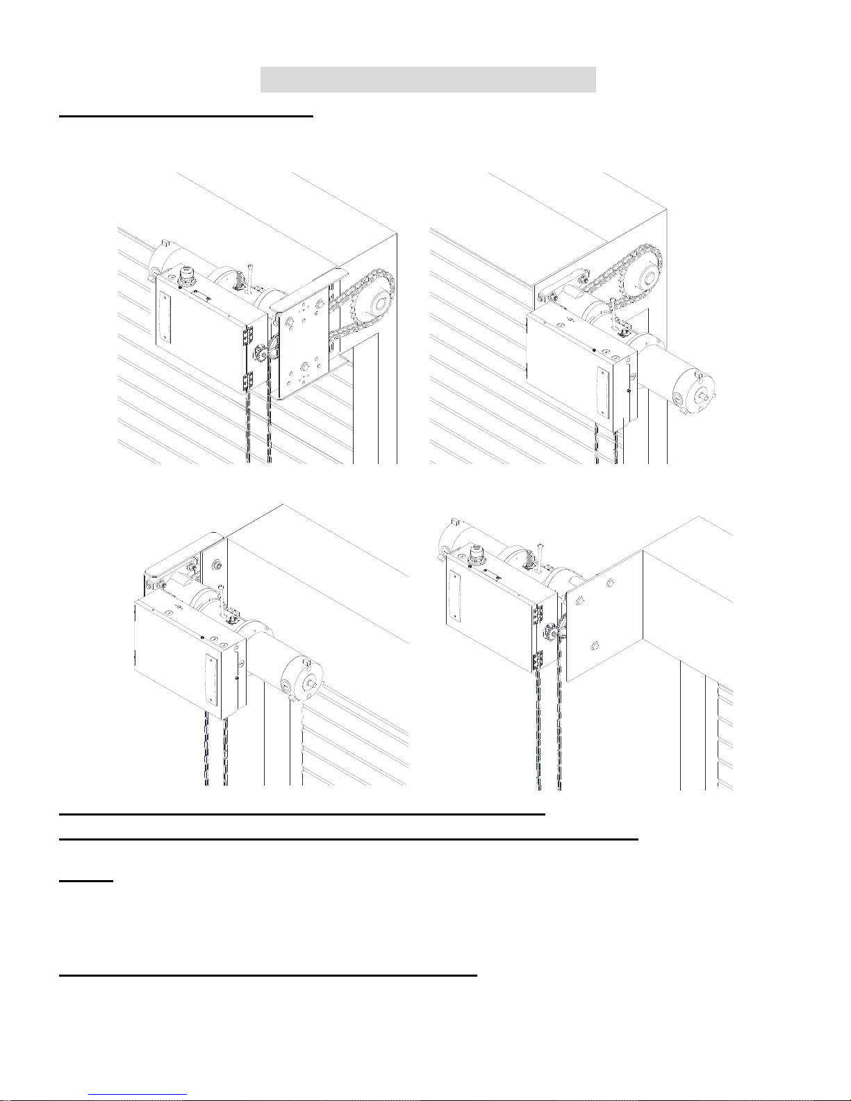
INSTALLATION INSTRUCTIONS
INSTALLATION POSITIONS
LS
RS
RA
LA
Consult factory for changes in installation positions.
Illustrations only, consult door manufacturer for install details.
NOTE: Any change in mounting position may result in a change of operator rotation and
consequently in a change of control functions. Consult factory for any changes. (LH=LS and
RA, RH=RS and LA)
Please see page 11 for Left and Right Switch.
3
U.S. Gear
07/17
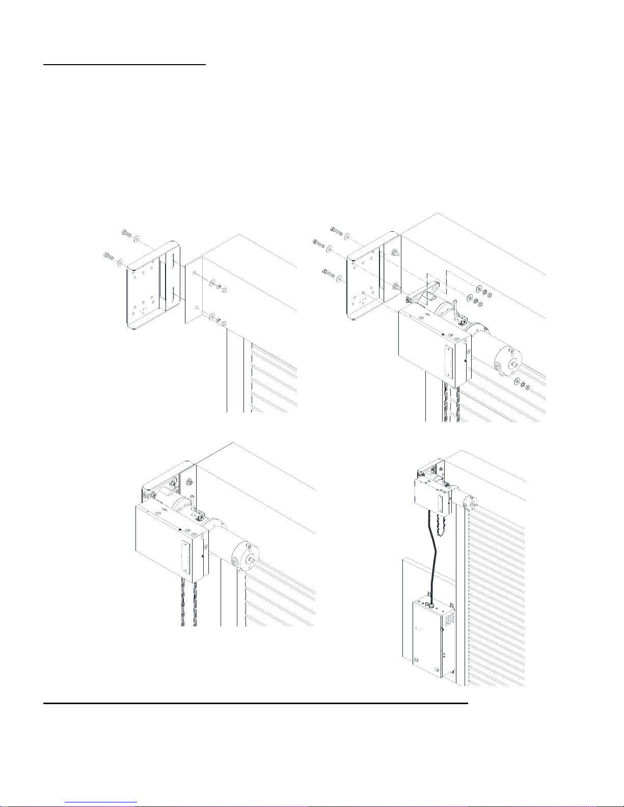
OPERATOR MOUNTING
1. Before the operator is installed, verify that the door is properly operating and balanced.
2. Make sure the layout of the mounting holes on the bracket are correct.
3. Bolt the operator mounting plate to the door bracket plate.
4. Attached and tighten mounting blots to the mounting plate.
5. Finally, mount the operator to the mounting plate.
Illustrations only, consult door manufacturer for install details.
4
U.S. Gear
07/17
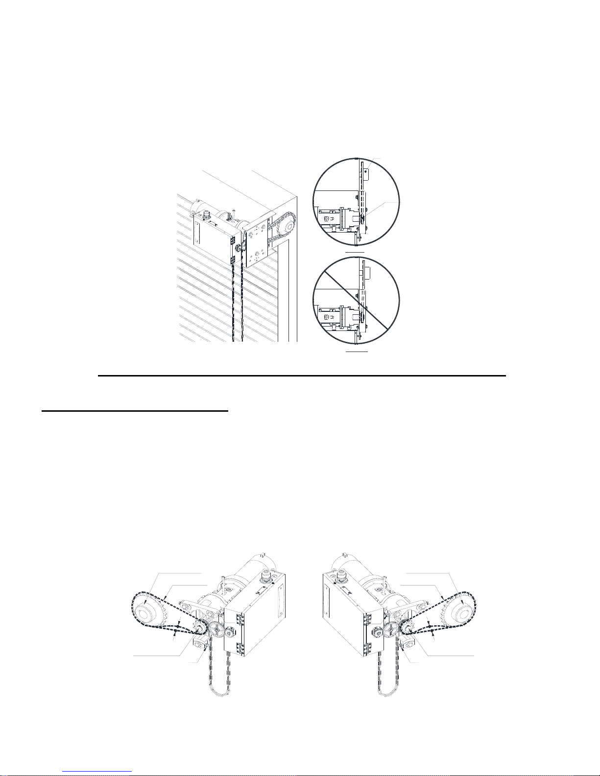
6. When the operator assembly is attached to the door bracket, be sure the door driven sprocket is
properly aligned with the operator drive sprocket before securing the driven sprocket to the shaft.
7. The shelf or bracket must provide adequate support for the operator. Prevent play between the
operator and the door shaft. The operator must be securely attached with the drive shaft parallel to
the door shaft. It may be necessary to field brace the operator/bracket.
Door
Sprocket
Operator
Output
Sprocket
Correct
Incorrect
Illustrations only, consult door manufacturer for install details.
DRIVE CHAIN ADJUSTMENT
NOTE: Use correct type, size and proper length of roller chain.
1. Adjust the drive chain by tilting or move the operator so that there is about 1/4” of slack when the
chain is depressed.
Note: The set screw included in the operator may be used for adjustment. (See figure - T1 and T2).
2. Once the drive chain has been tightened and the base leg screws have been set, and then tighten
the operator screws.
Door Sprocket
Drive Chain
T2
T2
Door Sprocket
Drive Chain
1/4"
Drive Sprocket
T1
5
Drive Sprocket
T1
1/4"
U.S. Gear
07/17
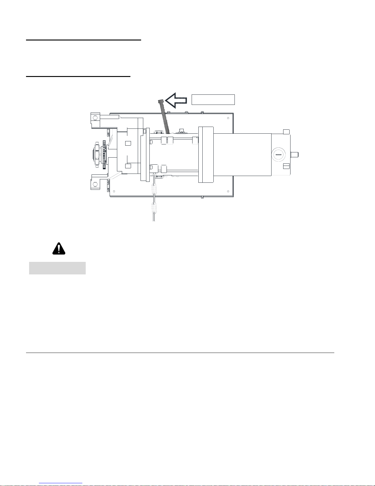
HAND CHAIN ADJUSTMENT
Cut and reconnect chain with different color link provided.
BRAKE RELEASE LEVER
Release
WARNING
1. Pressing the brake release lever will release the motor brake and can cause the door to move
uncontrolled.
2. Open-close-stop controls do not function while the brake release lever is pressed.
NOTE: A door sprung for emergency egress can open when the brake release lever is pressed.
Releasing the door operator brake, or loosening or removing any part of the
door operator drive system, can cause the door to close and cause death or
serious injury. Do NOT release the brake, or loosen or remove any part of
the door operator drive system, unless the door is closed, or the curtain is
secured in the open position to prevent uncoiling.
6
U.S. Gear
07/17
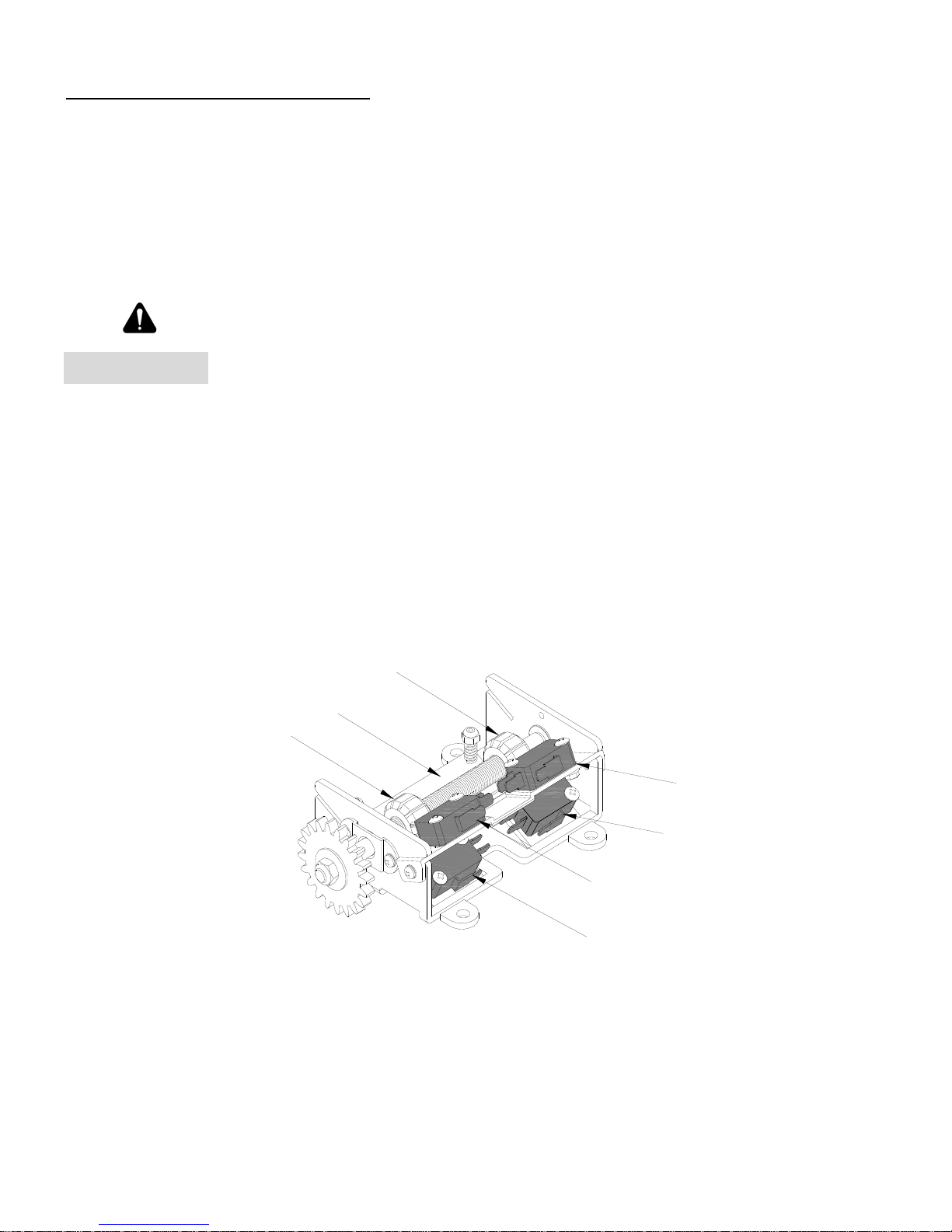
LIMIT SWITCH ADJUSTMENT
Make sure the limit cams are positioned between the limit switch actuators before proceeding
with adjustments.
1. Open / Remove the control panel cover.
2. Open or close door to determine the moving direction of the limit switch cams.
3. Open or close door to the desired position.
WARNING
4. While pressing the spring-loaded lever (G), which holds the limit switch cams in place, adjust the
limit switch cam (E or F) until the micro switch (C or D) clicking sound is heard.
5. If the limit switch cam cannot be rotated to its desired position, release the lever and move the door
away from the desired position, then adjust the limit switch cam to its desired position. It may be
necessary to repeat this step until the exact position has been reached.
6. Repeat step 3 and 4 for the opposite position. Adjust close limit cams so that actuator is engaged as
door fully seats at the floor.
7. Micro switch (A or B) can be adjusted to accommodate sensing edge cut-off position.
Disconnect power before adjusting limit switch cams.
F
G
E
B
D
A
C
NOTE: “C” is usually the opening side and “D” is usually the closing side.
7
U.S. Gear
07/17
 Loading...