

Page 1
Cornell-Plexi 18/20
Head or Combo
Owner’s Manual
DC Developments
Mmusical Equipment Design & Development
Unit 13 Rosshill Industrial Park, Sutton Road,
Southennd-on-Sea. Essex SS2 5PZ : 01702 610964
Page 2

Contents
1. Introduction
Construction and Design
2. Technical Design
3. Controls
4. Specifications
5. Tube Replacement and Valve Failure
Please read all instructions before operating unit!
If you require any further information regarding this amplifier or any other
CORNELL products, please do not hesitate to contact us.
WARNING:
TO PREVENT DAMAGE, FIRE OR SHOCK HAZARD, DO NOT EXPOSE THIS
UNIT TO RAIN OR MOISTURE.
NO USER SERVICEABLE PARTS INSIDE, REFER SERVICING TO QUALIFIED
PERSONNEL ONLY. THIS UNIT MUST BE EARTH GROUNDED.
1
Page 3

Introduction
Thank you for choosing a Cornell amplifier.
Your amplifier employs valve technology and is hand-built to H.M. Ministry of
Defence standards. Only top quality components are used so that you can enjoy
years of professional use.
Please take time to read this manual, to ensure that you get the best from
your amplifier.
Most guitarists of today will know some amplifier history and the name “Plexi” must
be one of the best known. Plexi is a nickname for an amplifier produced between
1963 to 1969, and consisted of a range of three amplifiers of 20,50 and 100 watts.
These amplifiers remain a legend which is reflected in their secondhand value.
Construction and Design
The Cornell-Plexi amplifiers are not one hundred percent copies of the old 1967
models, they are more like one hundred and ten percent copies!
Research has shown us that not all amplifiers made at this time were the same,
minor changes - not just in a visual sense, but also in the basic circuit design appear between batches made at the factory. We have taken the basic design to its
finest point, tailoring the components and adjusting the circuit to produce the
ultimate sound.
The Cornell-Plexi amplifier is not just a good-looking reproduction antique to be
admired, it is reproduces that classic sound and can be gigged and gigged and
gigged.
Cornell-Plexi Sound
The Cornell-Plexi amplifier has a great tone that is instantly recognised and
emulated. Some boffins will tell you that its tone is due to its simplicity and this is a
result of the minimum number of components in the signal path. Amplifiers of today
offer a wide range of tones and sounds resulting in a mass of controls that can
confuse even the most enthusiastic fiddler. The result of this is that most modern
amplifiers sound the same, with a noticeable loss of natural tone that can only be
reproduced by simple design and point to point wiring.
2
Page 4

Technical Design
Virtually all modern amplifiers are built using printed circuit boards, which contain
conductor tracks that connect components together, these conductor tracks often
run very close to one another. When this happens a small capacitance is produced
between them, the result of which is a substantial loss in both high frequency
response and harmonic richness. The Cornell-Plexi is designed to avoid this by
having specific point to point wiring.
Components in the Cornell-Plexi amplifier are mounted on a specially designed
board. This board is produced by the original manufacturer of the 1967 Plexi board
and Turret Tags are hand-riveted onto the board where the components are
mounted. These components are then sealed using a conformal coating to prevent
noise and the shortening of component life caused by moisture penetration.
The steel chassis holds specially designed, interleaved transformers, wound with
impregnated paper. The design ensures a very close reproduction of the full
harmonic spectrum of your guitar’s pick-ups.
The cabinet is of a rigid construction using best quality plywood. The covering is
both heavy duty and burn resistant, The cabinet is handsomely finished and
features original fittings.
The Pre-amplifier
The Cornell-Plexi is designed to be simple in use and yet produce the wide range
of sounds that the musician expects from a professional amplifier.
There are two independent channels each having its own volume control which
controls the overall loudness of the amplifier. The Tone controls are designed to
work over the entire frequency range of your guitar, allowing increased amounts of
low and high frequency adjustment. Channel Two has a brighter tone than that of
that of Channel One.
The Output Stage
Most modern amplifiers use Class AB1 or AB2 output designs which control the
grids of the output valves by a negative voltage – bias voltage. Should the bias
voltage be set too high, cross-over distortion occurs and is present constantly in the
sound of the amplifier, creating a “fuzzy” tone. If set too low, the valves might begin
to glow red which considerably reduces their lives resulting in expensive
replacements.
The Cornell-Plexi 18/20 has a Class A output design achieved by means of a fixed
bias resistor. The resistance valve is selected to complement exactly the
characteristics of the output valve. With its Class A output, the Cornell-Plexi 18/20
gives a sweeter tone with less distortion and avoids the need for bias adjustments.
3
Page 5

Controls
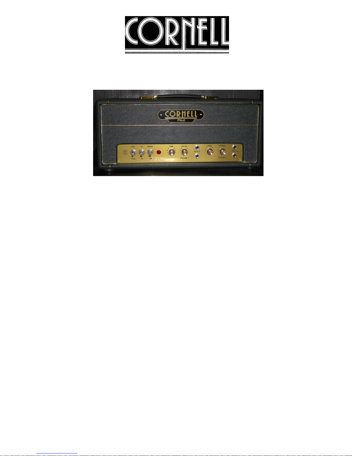
1. Input Hi & Lo.
Jack plug input connection for your electric guitar.
High impedance input connections for instruments.
Input Hi provides 6db more gain than the Lo input.
Both inputs are identical if used simultaneously.
2. Volume
Adjusts the gain of the pre-amp and is used in conjunction to set the overall
volume of the amplifier.
3. Tone
Adjusts the amount of low and high frequency boost.
4. Channel 2
Controls are the same as for Channel 1.
The overall tone of Channel 2 is brighter than Channel 1.
5. 18/20 Switch
Changes the rectification from semiconductor diode (20) to valve rectification
(18).
6. Low-High Switch
Reduces the output from 5 watts (low) to 20 watts when switched to the high
position.
7. Output
The two jack sockets are wired in parallel and are connected to an 8 ohm
speaker load via a jack lead. The output switch changes impedance from 8
(Toggle points “IN”) ohms to 4 ohms (Toggle points “OUT”).
8. Mains
When illuminated the valve heaters are on and there is power to the amplifier.
Mains Switch Operation
Do not operate mains switch without a 30 second delay between
operations.
An internal Thermistor reduces mains surges. It works by introducing a
resistance when switched on, after a few seconds the Thermistor is heated
and the resistance is reduced. When switched off it requires a few seconds to
cool and retain its resistance before the next switch on.
Mains Fuse
The fuse holder contains the mains fuse to the amplifier and protects the
amplifier from electrical faults.
Replace a failed fuse only with the same type and rating.
!
4
Page 6

Specifications
POWER..............................................115 Volt A-C 60hz 80 Watts US Model
230 Volt A-C 50hz 80Watts GB Model
FUSE..................................................T1 Amp for the 115 Volt US Model
T 600 m/Amp for the 230Volt GB Model
INPUT IMPEDANCE.................... Input HI 2.2 Meg Ohm.
Input LO 94k Ohm.
CONTROLS...................................... Pre-amp Volume, Bass, Middle, Treble,
Presence, Channel One and Two.
OUTPUT........................................... 20 Watt R.M.S Class ‘A’.
CABINET.......................................... Pine or lywood cabinet
Dimensions
Head: Height 7¾ ins 195mm
Width 19ins 480mm
Depth 8½ ins 215mm
Dimensions
Combo: Height 20 ins 510mm
Width 24ins 610mm
Depth 9 ins 230mm
WEIGHT
Head: 22 lbs 10Kgs.
Combo: 44 lbs 22 Kgs
OPTIONAL ON REQUEST....... Colours, Speaker Cabinet.
WARNING:
To prevent damage, fire or shock hazard, do not expose this unit to rain or
moisture.
No user serviceable parts inside, refer servicing to qualified personnel only.
This unit must be Earth grounded, use correct mains cord.
5
Page 7
6
Tube Replacement
Tube life varies depending upon playing style and application. Power tubes have a
much shorter life than pre-amp tubes which can last for years. To maintain the
optimum performance of your amplifier, the tubes should only be replaced with the
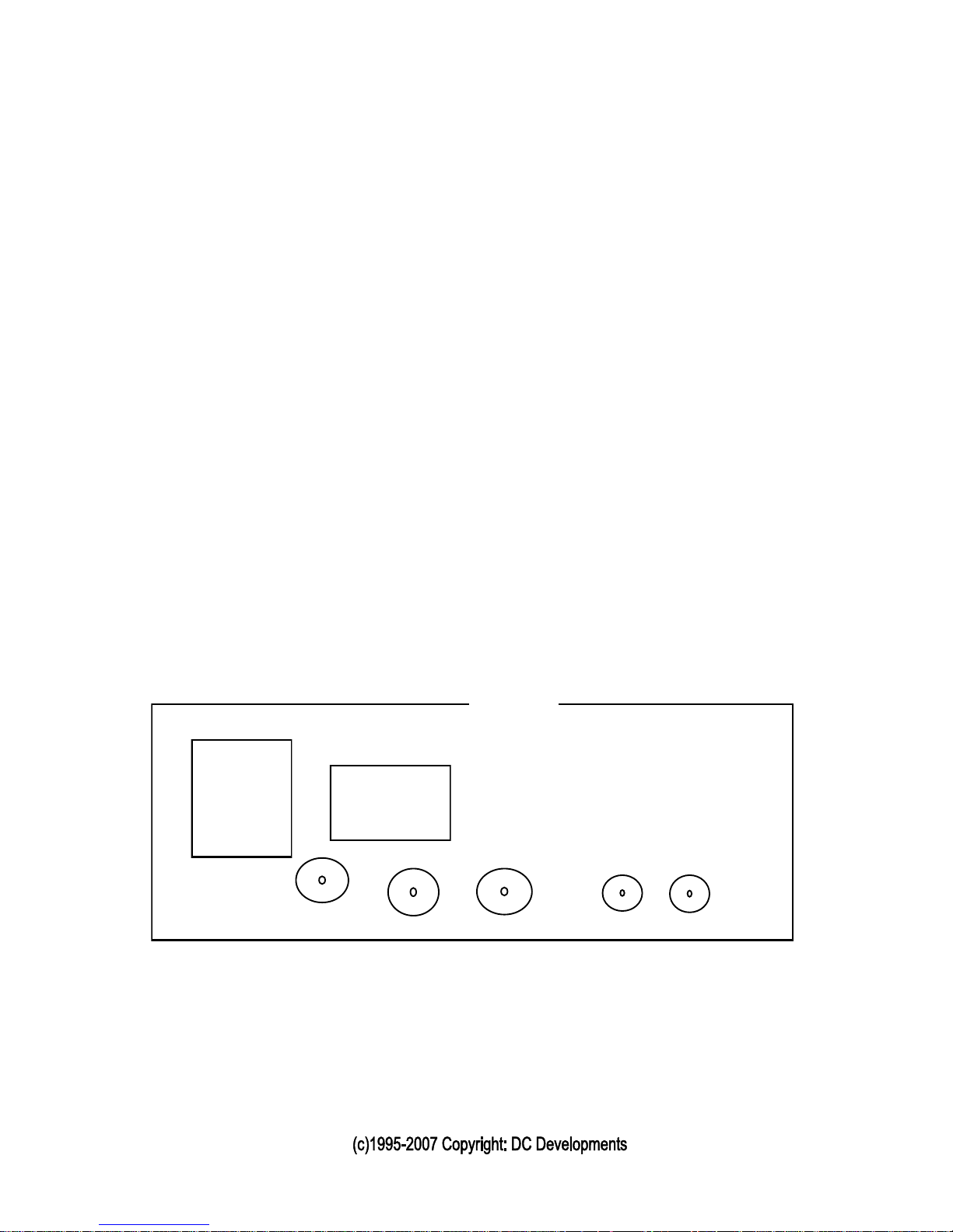
same type as specified on the tube illustration below.
When changing tubes ALWAYS unplug the amplifier and remember that the
TUBES ARE HOT! Wait for the tubes to cool or replace tubes when amplifier has
not been used for several hours.
Your Cornell-Plexi 18/20 amplifier has 4 valves: two pre-amp valves 12AX7 or
ECC83, two power valves EL84 and a rectifier GZ34.
Valve Failure
When a valve breaks down its internal elements can short. This can cause major
damage to the internal components of the amplifier and also be a possible fire risk.
There are two fuses which will break under faulty conditions: one fuse is mounted
on the back panel and the other is on the chassis. Remember to replace the fuses
with the same type and rating.
Remember – we are always happy to assist in any we can, so please do not
hesitate to contact us.
Chassis Valve Line Up
Mains
Transformer
Output
Transformer
EL84 EL84
ECC83
Front panel
CAUTION CHASSIS SURFACE HOT
GZ 34
ECC83
 Loading...