

Page 1
User Manual
Instant
Water
Heater
CIS-E363DCR
CIS-E369DCR
Page 2
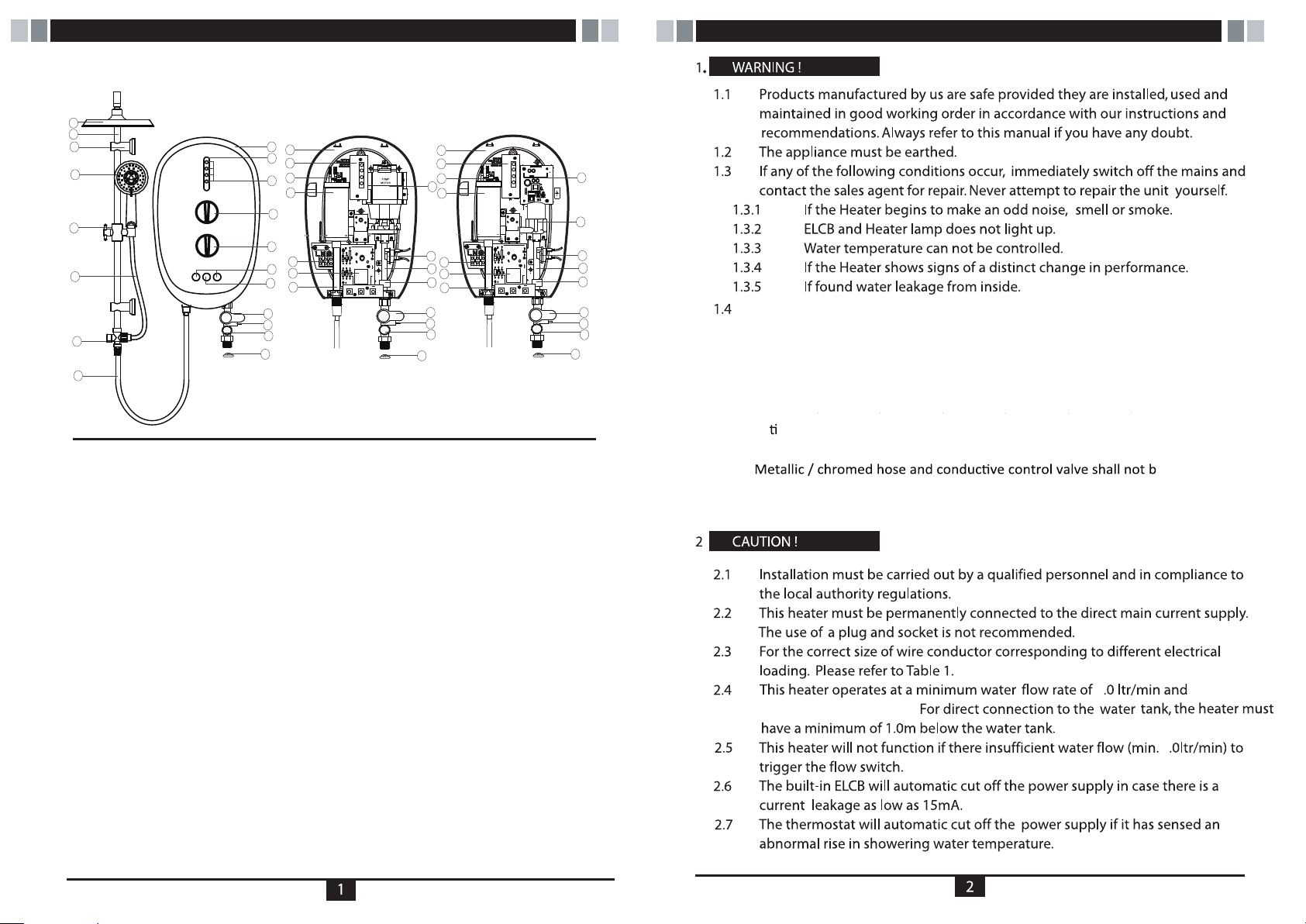
PARTS IDENTIFICATION
attention and check the shower temperature by using hand from time to time.
11
12
13
14
15
16
17
18
1
19
2
20
21
3
22
4
5
23
6
24
7
25
8
9
10
32
G
19
20
21
26
22
27
23
28
24
29
25
8
9
10
32
G
30
31
27
28
29
8
9
10
32
For Pump Model, it is highly recommended to connect the Water Inlet Connection to
tank storage supply, otherwise it may cause damage to the Pump Motor.
When the Shower is used by someone such as child, elderly person, sick person
1.5
and physically handicapped person, the concern person is kindly requested to pay
IMPORTANT SAFETY INFORMATION
Improper grounding could cause electrical shock.
1. Front Cover
2. Face Sticker
3. Indicator Lamp
4. Pump Knob
5. Temperature Control Knob
6. Test / Reset Button
7. Pump Booster Button
8. Stop Valve
9. Flow Regulator Valve
10. Filter Valve
11. Rain Shower Head
12. Sliding Rail
13. Wall Bracket
14. Hand Shower
15. Shower Holder
16. PVC Hose 1.5m
Fig 1.
17. Selector Valve
18. PVC Hose 1.0m
19. Heater Base
20. PCB Board
21. Thermostat
22. Heater Tank
23. Terminal Block
24. Main PCB Board
25. Water Outlet Connection
26. AC Pump
27. TRIAC
28. Water INLET Connection
29. Reed Switch Assy
30. SMPS PCB Board
31. D.C Silent Pump
32. Mesh Filter
User is advised to test and adjust the water temperature before bathing.
In me of lightning/thunder, switch "off'' the electric supply to the shower unit in
1.6
to protect the shower unit against possible damage.
e used.
1.7
advance
Note: When removing the unit from package, small amount of water may found inside.
This is normal as the unit is tested during manufacturing process.
maximum 2
working pressure of 6 bars.
2
Page 3
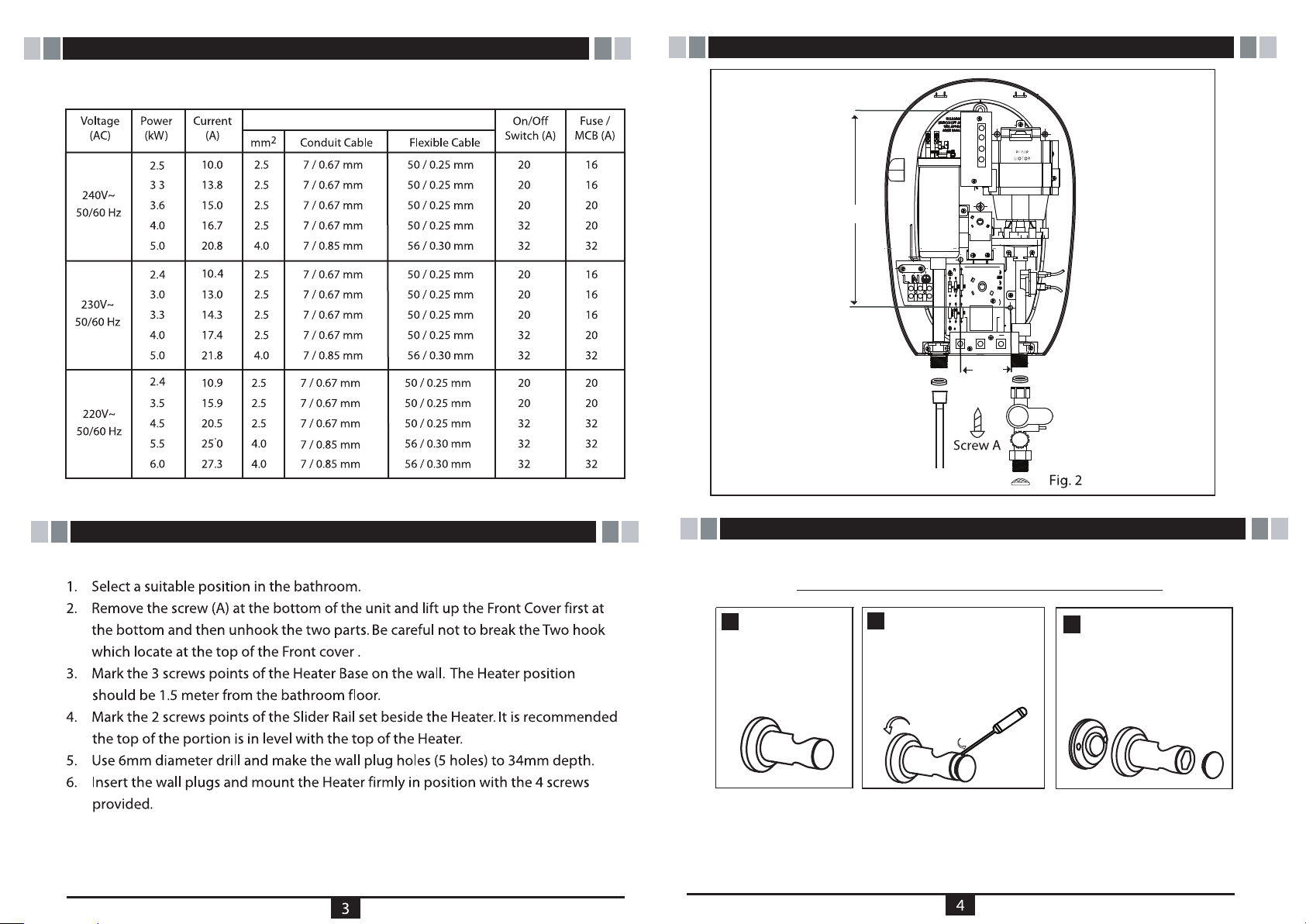
TABLE 1-ELECTRICAL LOADING TABLE
Minimum Conductor Size (csa)
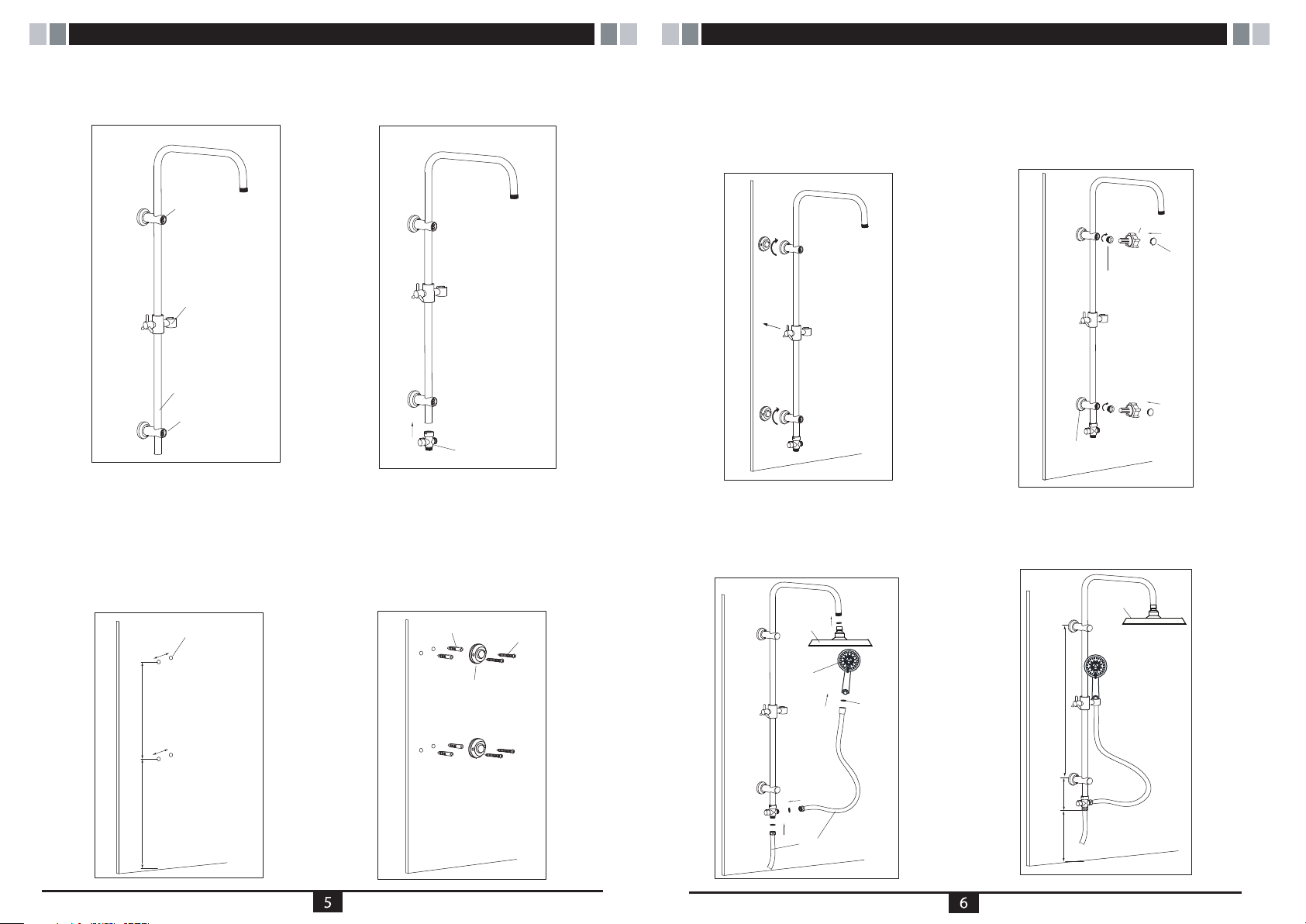
HEATER UNIT INSTALLATION DIAGRAM
255mm
G
65mm
INSTALL THE HEATER UNIT
RAIL BRACKET COVER & CAP DISMANTLE STEPS
1
RAIL BRACKET
RAIN SHOWER SET INSTALLATION PROCEDURES
OPEN THE RAIL
2
BRACKET COVER
BY TURNING ANTI
CLOCKWISE & USING
SCREW DRIVER TO
OPEN THE CAP
RAIL BRACKET
3
COVER COME-OUT
Page 4
continue from RAIN SHOWER SET INSTALLATION PROCEDURES continue from RAIN SHOWER SET INSTALLATION PROCEDURES
STEP 1
Insert the Top Rail Bracket, Adjustable
Shower Holder, & Bottom Rail Bracket
to the Slider Rail.
1.
top rail bracket
shower holder
slider rail
bottom rail bracket
STEP 2
Connect the Selector Valve to the
bottom of Slider Rail.
2.
STEP 5
Mount the Slider Rail (connected
with Rail Bracket, Adjustable
Shower Holder and Selector Valve)
to the mounting terminal
by turns the terminal cover.
5.
STEP 6
Remove the cover and cap from
the Rail Bracket (Fig. 3A) and
screw the rail bracket by turning
the cover clockwise. Using hexagon
tool to tighten the plastic nut to the
desire position and then replace
the cover.
6.
hexagon tool
rail
bracket cap
plastic nut
STEP 3
Select a suitable position for the Rain
Shower Set then mark 4 screws point
(2 on top and 2 on bottom). The gap of
2 screw hole was 38mm. It is
recommended that the Top Rail Bracket
position at height of 1950mm to the floor
and Bottom Rail Bracket 1300mm to the
floor.
wall plug hole
3.
38mm
650mm
38mm
1300mm
selector valve
STEP 4
Use 6mm diameter drill and
make the wall plug holes in
depth of 34mm. Insert the wall
plugs and mounting terminal
firmly in position with the
screw provided.
4.
wall plug
mounting terminal
screw
STEP 7
Connect the Rain Shower Head to the top of
Slider Rail, 1.5Meter PVC Hose to Hand Shower
Head and 1Meter PVC Hose to the Heater.
Connected be sure to put in the Rubber Washer.
7.
rain
shower
head
shower
head
c
d
PVC hose
b
a
rubber
washer
rail bracket
cover
STEP 8
Recommended Height for Rain
Shower Set.
8.
rain
shower
head
650mm
100mm
1200mm
Page 5
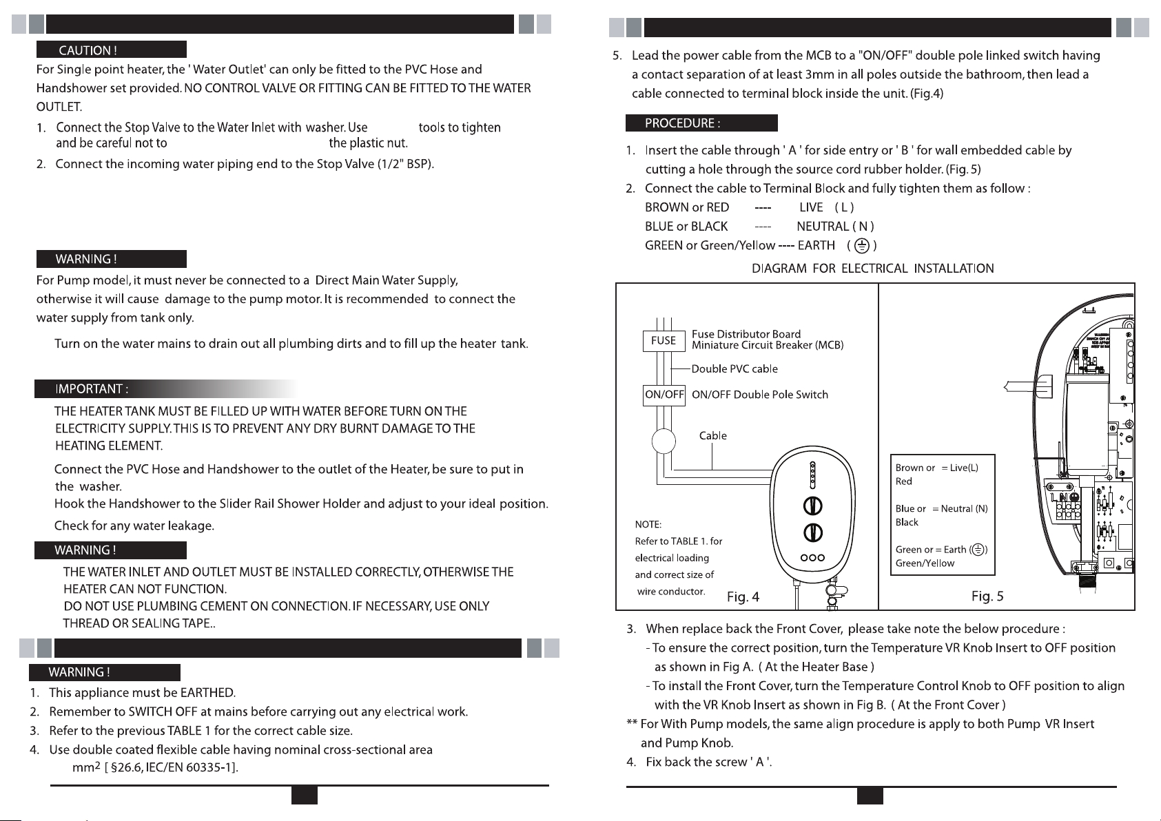
PLUMBING PROCEDURE - IMPORTANT
correct
over tighten and damage
Make sure to put the Mesh Filter between Stop Valve and incoming
water piping.
3. If in any case, the Stop Valve is not use or omitted, make sure to put the
Mesh Filter between the heater unit inlet pipe and incoming water pipe.
4.
5.
Do not use white tape during installation.
continue from ELECTRICAL INSTALLATION -IMPORTANT
(*)
Side Entry A
6.
7.
8.
B
G
.
To ensure the power cord NOT
(*)
touch copper flange.
.
ELECTRICAL INSTALLATION -IMPORTANT
Improper grounding could cause electrical shock.
of
2.5
7 8
Page 6
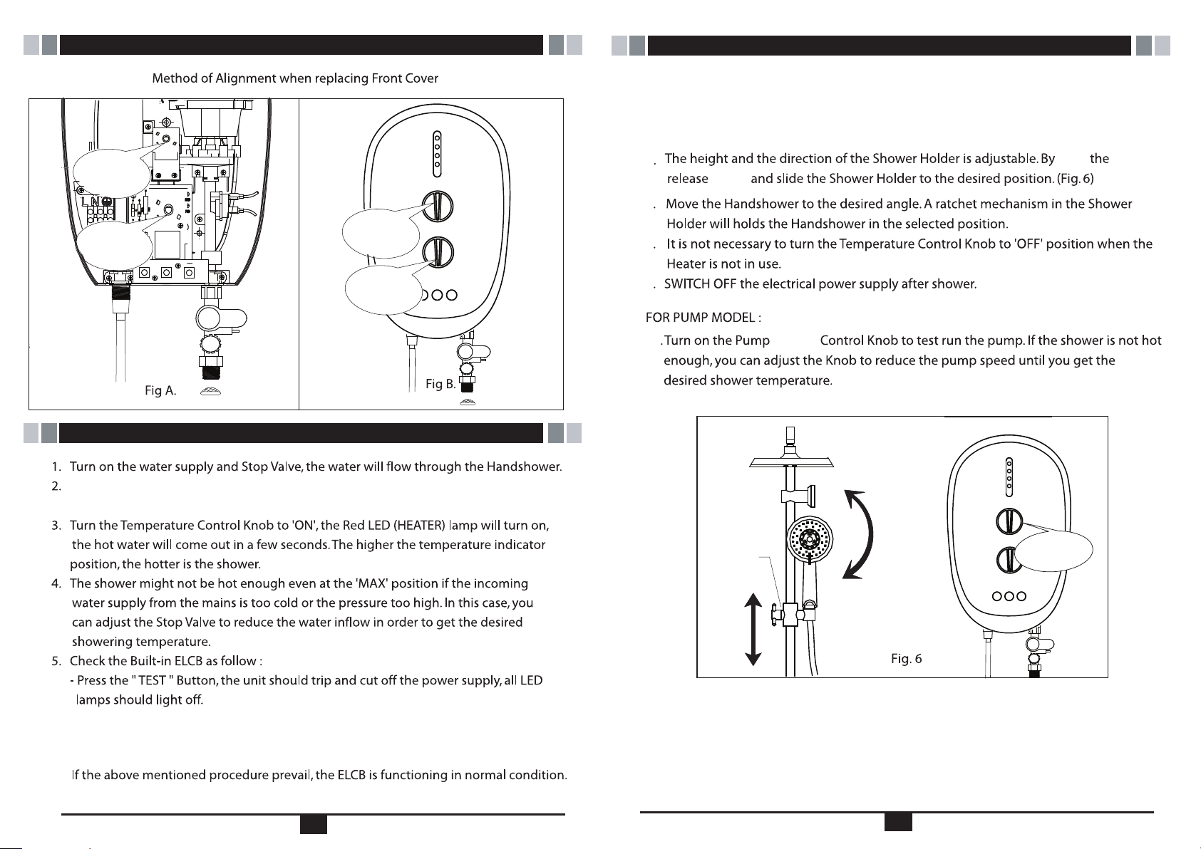
Position
this Way
Position
this Way
continue from ELECTRICAL INSTALLATION - IMPORTANT
Position
G
this Way
continue from TEST RUN
6. The earth indicator will turn "ON" if wiring is done correctly. When earth indicator is "OFF",
please check the following:-
- Improper earthing
- Live (L) and Neutral (N) reversed.
7
turn
knob
8
9
Position
this Way
TEST RUN
Switch on the electrical supply. The 3 LED indicator light shall run ON/OFF 3 times
in sequences to indicate the set are self checking.
10
11
Release
Knob
ON/OFF
VARIABLE
SWITCH
- Press the ‘’RESET’’ button, the 3 LED indicator lights shall run ON/OFF 3 times in sequences
to indicate self check as in No.2 above and the Heater Unit should resume normal function,
the Green LED Indicator should light on.
9
10
Page 7
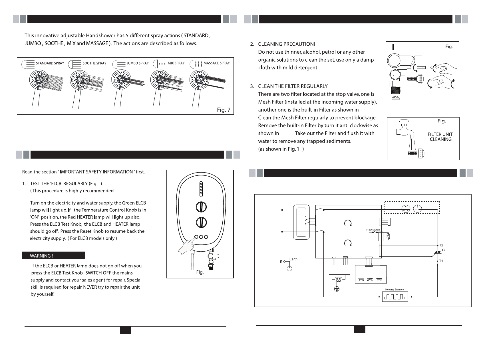
HAND SHOWER ACTION
continue from MAINTENANCE
(Fig. 9 & Fig. 10 )
Fig. 9.
OPEN
INTERNAL
STRAINER
BUILT-IN FILTER
MESH FILTER
FLOW REGULATOR
CLOSE
OPEN
CLOSE
9
Clean the Handshower Head holes by using the soft brush from time to time.
(Recommended once a week)
Note: Take care not to damage the holes of the Handshower Head during cleaning.
MAINTENANCE
8
test at least
once a month).
8
Fig. 9.
LIVE
(L
Main Supply
220 -240 V ~ a.c
NEUTRAL
(N
0
WIRING DIAGRAM
WIRING DIAGRAM - DPDT ( SILENT PUMP MODEL)
Auto
)
in
in
)
Nout
Lout
SMPS PCB
ASSY
Pump On/Off
Power On/Off
Temperature Control
Silent Pump,
Electronic ELCB,
15mA Sensitivity
Test
On/Off Switch
Pump
Booster
Thermostat
Heater Control
T2
G
Reset
Led Board
Manual
Thermostat
10
TRIAC
11
12
Page 8
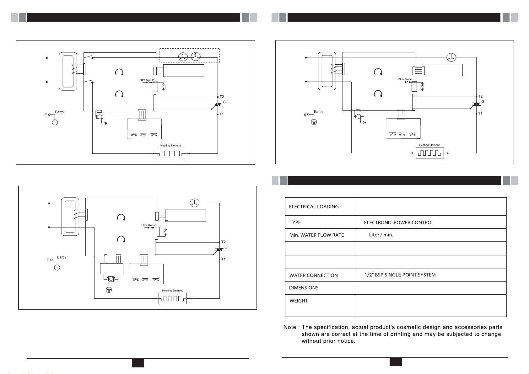
continue from WIRING DIAGRAM
continue from WIRING DIAGRAM
LIVE
(L
in
)
Main Supply
220 -240 V ~ a.c
NEUTRAL
in
)
(N
Note : (*) For Pump Model
WIRING DIAGR
LIVE
(L
in
)
Main Supply
220 -240 V ~ a.c
NEUTRAL
(N
in
WIRING DIAGRAM - DPDT MODEL
Auto
Thermostat
Heater Control
T2
G
(*)
Reset
Nout
Lout
Pump On/Off
Power On/Off
Temperature Control
(*) For PUMP Model
AC PUMP,
120W, 240V d.c
Electronic ELCB,
15mA Sensitivity
Test
On/Off Switch
Pump
Booster
Led Board
Manual
Thermostat
TRIAC
LIVE
(L
Main Supply
220 -240 V ~ a.c
NEUTRAL
(N
WIRING DIAGR
)
in
in
)
AM - SINGLE POLE MODEL
Pump On/Off
Power On/Off
Temperature Control
(*) For PUMP Model
AC PUMP,
120W, 240V d.c
Test
On/Off Switch
Electronic ELCB,
15mA Sensitivity
Pump
Booster
Heater Control
T2
G
(*)
Reset
Led Board
Auto
Thermostat
TRIAC
Note : (*) For Pump Model
AM - SINGLE POLE MODEL ( SILENT PUMP MODEL)
Auto
Thermostat
ELECTRICAL SPECIFICATION
3.3kW 230Va.c.
Led Board
Pump On/Off
)
Power On/Off
Temperature Control
SMPS PCB
ASSY
Silent Pump,
Test
On/Off Switch
Electronic ELCB,
15mA Sensitivity
Pump
Booster
T2
G
Reset
Heater Control
TRIAC
Min. INLET WATER PRESSURE
Max. INLET WATER PRESSURE
2
0.1 Bar (10kPa)
6.0 Bar (0.6MPa)
250 X 400 X 105 mm
13
: 5.3 Kg - ELCB, SILENT PUMP
ESP
EP
6.0 Kg - ELCB,
:
A.C PUMP
14
 Loading...