

Cornelius WCC502-W, WCC500-A, WCF510-A, WCF510-W, WCF512-A Service Manual
...
CONTINUOUS FLOW ICEMAKER
500, 700, 1000, 2000 - Series
Service Manual
Release Date: May 27, 2004
Publication Number: 630460174SER
Revision Date: February 24, 2011
Revision: E
Visit the IMI Cornelius web site at www.cornelius.com for all your Literature needs.

The products, technical information, and instructions contained in this manual are subject to change without notice.
These instructions are not intended to cover all details or variations of the equipment, nor to provide for every possi
ble contingency in the installation, operation or maintenance of this equipment. This manual assumes that the person(s) working on the equipment have been trained and are skilled in working with electrical, plumbing, pneumatic,
and mechanical equipment. It is assumed that appropriate safety precautions are taken and that all local safety and
construction requirements are being met, in addition to the information contained in this manual.
This Product is warranted only as provided in Cornelius’ Commercial Warrant applicable to this Product and is subject to all of the restrictions and limitations contained in the Commercial Warranty.
Cornelius will not be responsible for any repair, replacement or other service required by or loss or damage resulting
from any of the following occurrences, including but not limited to, (1) other than normal and proper use and normal
service conditions with respect to the Product, (2) improper voltage, (3) inadequate wiring, (4) abuse, (5) accident,
(6) alteration, (7) misuse, (8) neglect, (9) unauthorized repair or the failure to utilize suitably qualified and trained per
sons to perform service and/or repair of the Product, (10) improper cleaning, (11) failure to follow installation, operating, cleaning or maintenance instructions, (12) use of “non-authorized” parts (i.e., parts that are not 100%
compatible with the Product) which use voids the entire warranty, (13) Product parts in contact with water or the
product dispensed which are adversely impacted by changes in liquid scale or chemical composition.
Contact Information:
To inquire about current revisions of this and other documentation or for assistance with any Cornelius product contact:
www.cornelius.com
800-238-3600
-
-
Trademarks and Copyrights:
This document contains proprietary information and it may not be reproduced in any way without permission from
Cornelius.
Printed in U.S.A.

TABLE OF CONTENTS
Safety Instructions . . . . . . . . . . . . . . . . . . . . . . . . . . . . . . . . . . . . . . . . . . . . . . . . . . . . . . . . . . . . . . . . . . . . . . . . .1
Read and Follow ALL Safety Instructions . . . . . . . . . . . . . . . . . . . . . . . . . . . . . . . . . . . . . . . . . . . . . . . . . . . . . 1
Safety Overview . . . . . . . . . . . . . . . . . . . . . . . . . . . . . . . . . . . . . . . . . . . . . . . . . . . . . . . . . . . . . . . . . . . . . 1
Recognition . . . . . . . . . . . . . . . . . . . . . . . . . . . . . . . . . . . . . . . . . . . . . . . . . . . . . . . . . . . . . . . . . . . . . . . . .1
Different Types of Alerts . . . . . . . . . . . . . . . . . . . . . . . . . . . . . . . . . . . . . . . . . . . . . . . . . . . . . . . . . . . . . . . . . . .1
Safety Tips . . . . . . . . . . . . . . . . . . . . . . . . . . . . . . . . . . . . . . . . . . . . . . . . . . . . . . . . . . . . . . . . . . . . . . . . . . . . .1
Qualified Service Personnel . . . . . . . . . . . . . . . . . . . . . . . . . . . . . . . . . . . . . . . . . . . . . . . . . . . . . . . . . . . . . . . . 1
Safety Precautions . . . . . . . . . . . . . . . . . . . . . . . . . . . . . . . . . . . . . . . . . . . . . . . . . . . . . . . . . . . . . . . . . . . . . . .2
Shipping And Storage . . . . . . . . . . . . . . . . . . . . . . . . . . . . . . . . . . . . . . . . . . . . . . . . . . . . . . . . . . . . . . . . . . . . 2
General Description . . . . . . . . . . . . . . . . . . . . . . . . . . . . . . . . . . . . . . . . . . . . . . . . . . . . . . . . . . . . . . . . . . . . . . . . 3
Specification Chart . . . . . . . . . . . . . . . . . . . . . . . . . . . . . . . . . . . . . . . . . . . . . . . . . . . . . . . . . . . . . . . . . . . . . . .3
Bin Control . . . . . . . . . . . . . . . . . . . . . . . . . . . . . . . . . . . . . . . . . . . . . . . . . . . . . . . . . . . . . . . . . . . . . . . . . . . . .6
Gearmotor . . . . . . . . . . . . . . . . . . . . . . . . . . . . . . . . . . . . . . . . . . . . . . . . . . . . . . . . . . . . . . . . . . . . . . . . . . . . .6
Cleaning and Sanitizing . . . . . . . . . . . . . . . . . . . . . . . . . . . . . . . . . . . . . . . . . . . . . . . . . . . . . . . . . . . . . . . . . . . . .7
Icemaker Cleaning and Sanitizing Procedures . . . . . . . . . . . . . . . . . . . . . . . . . . . . . . . . . . . . . . . . . . . . . . . . . 7
Maintenance . . . . . . . . . . . . . . . . . . . . . . . . . . . . . . . . . . . . . . . . . . . . . . . . . . . . . . . . . . . . . . . . . . . . . . . . . . . .7
Monthly . . . . . . . . . . . . . . . . . . . . . . . . . . . . . . . . . . . . . . . . . . . . . . . . . . . . . . . . . . . . . . . . . . . . . . . . . . . . . . . .7
Quarterly . . . . . . . . . . . . . . . . . . . . . . . . . . . . . . . . . . . . . . . . . . . . . . . . . . . . . . . . . . . . . . . . . . . . . . . . . . . . . . 7
Semi-annually . . . . . . . . . . . . . . . . . . . . . . . . . . . . . . . . . . . . . . . . . . . . . . . . . . . . . . . . . . . . . . . . . . . . . . . . . .8
Water Level Control . . . . . . . . . . . . . . . . . . . . . . . . . . . . . . . . . . . . . . . . . . . . . . . . . . . . . . . . . . . . . . . . . . . . . . . .9
How Water Level Control Works . . . . . . . . . . . . . . . . . . . . . . . . . . . . . . . . . . . . . . . . . . . . . . . . . . . . . . . . . . . .9
Purpose . . . . . . . . . . . . . . . . . . . . . . . . . . . . . . . . . . . . . . . . . . . . . . . . . . . . . . . . . . . . . . . . . . . . . . . . . . . . . . . 9
To Replace Water Level Control . . . . . . . . . . . . . . . . . . . . . . . . . . . . . . . . . . . . . . . . . . . . . . . . . . . . . . . . . . . . 9
To Replace Water Level Safety Switch . . . . . . . . . . . . . . . . . . . . . . . . . . . . . . . . . . . . . . . . . . . . . . . . . . . . . . . 9
Electrical . . . . . . . . . . . . . . . . . . . . . . . . . . . . . . . . . . . . . . . . . . . . . . . . . . . . . . . . . . . . . . . . . . . . . . . . . . . . . . . . 10
Refrigeration System . . . . . . . . . . . . . . . . . . . . . . . . . . . . . . . . . . . . . . . . . . . . . . . . . . . . . . . . . . . . . . . . . . . . . . 13
Refrigeration System Adjustments . . . . . . . . . . . . . . . . . . . . . . . . . . . . . . . . . . . . . . . . . . . . . . . . . . . . . . . . . . 13
Expansion Valve . . . . . . . . . . . . . . . . . . . . . . . . . . . . . . . . . . . . . . . . . . . . . . . . . . . . . . . . . . . . . . . . . . . . . . .13
Adjustment and Troubleshooting . . . . . . . . . . . . . . . . . . . . . . . . . . . . . . . . . . . . . . . . . . . . . . . . . . . . . . . . . . .13
Condenser Modulating Valve . . . . . . . . . . . . . . . . . . . . . . . . . . . . . . . . . . . . . . . . . . . . . . . . . . . . . . . . . . . . . .14
Condenser Modulating Valve Removal . . . . . . . . . . . . . . . . . . . . . . . . . . . . . . . . . . . . . . . . . . . . . . . . . . . . . .15
Motor Check . . . . . . . . . . . . . . . . . . . . . . . . . . . . . . . . . . . . . . . . . . . . . . . . . . . . . . . . . . . . . . . . . . . . . . . . . . . 16
Start Relay . . . . . . . . . . . . . . . . . . . . . . . . . . . . . . . . . . . . . . . . . . . . . . . . . . . . . . . . . . . . . . . . . . . . . . . . . . . .16
To Replace Gearmotor Assembly . . . . . . . . . . . . . . . . . . . . . . . . . . . . . . . . . . . . . . . . . . . . . . . . . . . . . . . . . .17
Installation and Shaft Seal Replacement 500 . . . . . . . . . . . . . . . . . . . . . . . . . . . . . . . . . . . . . . . . . . . . . . . . . 17
Auger and Extruding Head Removal . . . . . . . . . . . . . . . . . . . . . . . . . . . . . . . . . . . . . . . . . . . . . . . . . . . . . . . . 18
Installation and Shaft Seal Replacement 700 & 1000 . . . . . . . . . . . . . . . . . . . . . . . . . . . . . . . . . . . . . . . . . . .19
Upper Nut and Bearing Assembly . . . . . . . . . . . . . . . . . . . . . . . . . . . . . . . . . . . . . . . . . . . . . . . . . . . . . . . . . . 19
To Replace Bearing . . . . . . . . . . . . . . . . . . . . . . . . . . . . . . . . . . . . . . . . . . . . . . . . . . . . . . . . . . . . . . . . . 19
Electrical Checkout . . . . . . . . . . . . . . . . . . . . . . . . . . . . . . . . . . . . . . . . . . . . . . . . . . . . . . . . . . . . . . . . . . . . . 20
Overload Check . . . . . . . . . . . . . . . . . . . . . . . . . . . . . . . . . . . . . . . . . . . . . . . . . . . . . . . . . . . . . . . . . . . . . . . .20
Compressor Check . . . . . . . . . . . . . . . . . . . . . . . . . . . . . . . . . . . . . . . . . . . . . . . . . . . . . . . . . . . . . . . . . . . . .20
Capacitor Check . . . . . . . . . . . . . . . . . . . . . . . . . . . . . . . . . . . . . . . . . . . . . . . . . . . . . . . . . . . . . . . . . . . . . . . .21
Safety Controls . . . . . . . . . . . . . . . . . . . . . . . . . . . . . . . . . . . . . . . . . . . . . . . . . . . . . . . . . . . . . . . . . . . . . . . . .21
Troubleshooting . . . . . . . . . . . . . . . . . . . . . . . . . . . . . . . . . . . . . . . . . . . . . . . . . . . . . . . . . . . . . . . . . . . . . . . . . .23
Continuous Flow Icemaker Service Manual
!
DANGER:
!
WARNING:
CAUTION:
!
!
WARNING:
!
SAFETY INSTRUCTIONS
READ AND FOLLOW ALL SAFETY INSTRUCTIONS
Safety Overview
• Read and follow ALL SAFETY INSTRUCTIONS in this manual and any warning/caution labels on the unit (decals, labels or
laminated cards).
• Read and understand ALL applicable OSHA (Occupational Safety and Health Administration) safety regulations before
operating this unit.
Recognition
Recognize Safety Alerts
This is the safety alert symbol. When you see it in this manual or on the unit,
be alert to the potential of personal injury or damage to the unit.
DIFFERENT TYPES OF ALERTS
Indicates an immediate hazardous situation which if not avoided WILL result in serious injury, death or equipment
damage.
Indicates a potentially hazardous situation which, if not avoided, COULD result in serious injury, death, or equipment
damage.
Indicates a potentially hazardous situation which, if not avoided, MAY result in minor or moderate injury or equipment
damage.
SAFETY TIPS
• Carefully read and follow all safety messages in this manual and safety signs on the unit.
• Keep safety signs in good condition and replace missing or damaged items.
• Learn how to operate the unit and how to use the controls properly.
• Do not let anyone operate the unit without proper training. This appliance is not intended for use by very young children or
infirm persons without supervision. Young children should be supervised to ensure that they do not play with the appliance.
• Keep your unit in proper working condition and do not allow unauthorized modifications to the unit.
QUALIFIED SERVICE PERSONNEL
Only trained and certified electrical, plumbing and refrigeration technicians should service this unit. ALL WIRING AND
PLUMBING MUST CONFORM TO NATIONAL AND LOCAL CODES. FAILURE TO COMPLY COULD RESULT IN
SERIOUS INJURY, DEATH OR EQUIPMENT DAMAGE.
© 2004-2011, IMI Cornelius Inc. - 1 - Publication Number: 630460174SER
Continuous Flow Icemaker Service Manual
!
WARNING:
CAUTION:
!
CAUTION:
!
SAFETY PRECAUTIONS
This unit has been specifically designed to provide protection against personal injury. To ensure continued protection
observe the following:
Disconnect power to the unit before servicing following all lock out/tag out procedures established by the user. Verify
all of the power is off to the unit before any work is performed.
Failure to disconnect the power could result in serious injury, death or equipment damage.
Always be sure to keep area around the unit clean and free of clutter. Failure to keep this area clean may result in
injury or equipment damage.
SHIPPING AND STORAGE
Before shipping, storing, or relocating the unit, the unit must be sanitized and all sanitizing solution must be drained
from the system. A freezing ambient environment will cause residual sanitizing solution or water remaining inside the
unit to freeze resulting in damage to internal components.
Publication Number: 630460174SER - 2 - © 2004-2011, IMI Cornelius Inc.
Continuous Flow Icemaker Service Manual
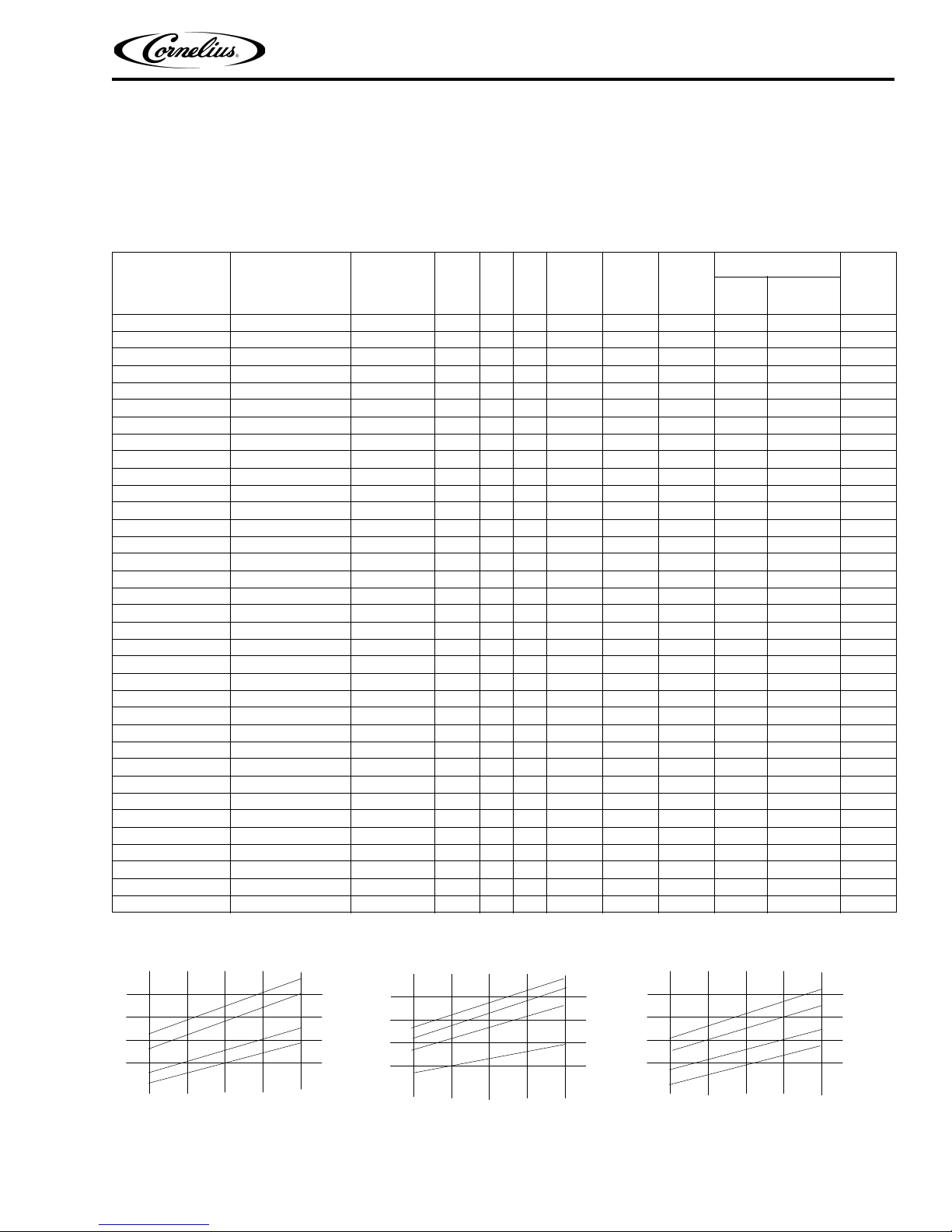
400
380
360
340
320
300
280
260
240
650
600
550
500
450
400
350
1100
1000
900
800
700
600
Capacity Lbs./24 hr.
Capacity Lbs./24 hr.
Capacity Lbs./24 hr.
90 80
70 60
50
90 80 70 60 50
90 80 70 60 50
–50 –70 –90 –100
Water Temperature Deg. F
Water Temperature Deg. F
Water Temperature Deg. F
Air Temperature Deg. F
Air Temperature Deg. F
Air Temperature Deg. F
–50 –70 –90 –100
–50 –70 –90 –100
WCC500
WCC700
WCC1000
GENERAL DESCRIPTION
This section gives the Unit description, theory of operation, and design data for continuous flow icemaker series
500, 700, 1000, and 2000.
SPECIFICATION CHART
Models
Condensing
Unit
VAC HZ PH Wi r e
Comp.
RLA
Fan
Amps
GRMT
R
Amps
Refrigerant
Oz. Type
Circuit
Fuse
WCC500-A Air Cooled 115 60 1 2 10.1 1.1 2 24 R404A 20
WCC500-W Water Cooled 115 60 1 2 10.1 N/A 2 11 R404A 20
WCC502-A Air Cooled 220/240 50 1 2 5.3 0.5 1.6 24 R404A 20
WCC502-W Water Cooled 220/240 50 1 2 5.3 N/A 1.6 11 R404A 20
WCF510-A Air Cooled 115 60 1 2 10.1 1.1 2 24 R404A 20
WCF510-W Water Cooled 115 60 1 2 10.1 N/A 2 11 R404A 20
WCF512-A Air Cooled 220/240 50 1 2 5.3 0.5 1.6 24 R404A 20
WCF512-W Water Cooled 220/240 50 1 2 5.3 N/A 1.6 11 R404A 20
WCC700-A Air Cooled 115 60 1 2 14.6 1.6 2 17.5 R404A 20
WCC700-W Water Cooled 115 60 1 2 12 N/A 2 13 R404A 20
WCC701-A Air Cooled 208/230 60 1 2 7.7 1.6 2 24 R404A 20
WCC701-W Water Cooled 208/230 60 1 2 7.7 N/A 2 13 R404A 20
WCC702-A Air Cooled 220/240 50 1 2 8.2 0.5 1.6 24 R404A 20
WCC702-W Water Cooled 220/240 50 1 2 8.2 N/A 1.6 13 R404A 20
WCF710-A Air Cooled 115 60 1 2 14.6 1.6 2 17.5 R404A 20
WCF710-W Water Cooled 115 60 1 2 12 N/A 2 13 R404A 20
WCC711-A Air Cooled 208/230 60 1 2 7.7 1.6 2 24 R404A 20
WCC711-W Water Cooled 208/230 60 1 2 7.7 N/A 2 13 R404A 20
WCF712-A Air Cooled 220/240 50 1 2 8.2 0.5 1.6 24 R404A 20
WCF712-W Water Cooled 220/240 50 1 2 8.2 N/A 1.6 13 R404A 20
WCC1001-A Air Cooled 208/230 60 1 2 7.5 0.85 2 26 R404A 20
WCC1001-W Water Cooled 208/230 60 1 2 7.5 N/A 2 17 R404A 20
WCC1002-A Air Cooled 220/240 50 1 2 8.9 0.85 2 26 R404A 20
WCF1101-A Air Cooled 208/230 60 1 2 7.5 0.85 2 26 R404A 20
WCF1101-W Water Cooled 208/230 60 1 2 7.5 N/A 2 17 R404A 20
WCF1102-A Air Cooled 220/240 50 1 2 8.9 0.85 2 26 R404A 20
WCC1001-R Remote 220/240 60 1 2 7.5 N/A 2 120 R404A 15
WCF1101-R Remote 208/230 60 1 2 7.5 N/A 2 120 R404A 15
WCC2001–A Air–Cooled 208/230 60 1 2 12.9 .85 (2) 2 46 R404A 25
WCC2001–R Remote 208/230 60 1 2 12.9 1.7 (2) 2 220 R404A 25
WCC2001–W Water Cooled 208/230 60 1 2 12.9 N/A (2) 2 28 R404A 25
WCC2002–A Air Cooled 220/240 50 1 2 11.4 .85 (2) 2 46 R404A 25
WCF2201–A Air–Cooled 208/230 60 1 2 12.9 .85 (2) 2 46 R404A 25
WCF2201–W Water Cooled 208/230 60 1 2 12.9 N/A (2) 2 28 R404A 25
WCF2202–A Air Cooled 220/240 50 1 2 11.4 .85 (2) 2 46 R404A 25
NOTE: For units not listed in above chart, refer to nameplate or contact factory service.
© 2004-2011, IMI Cornelius Inc. - 3 - Publication Number: 630460174SER
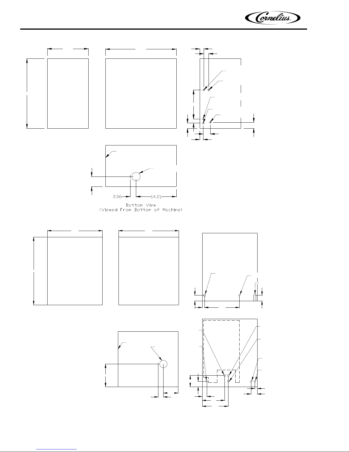
24.50
14.50
25.00 1.38
1.75
INLET 3/8 FLARED
WATER COOLED ONLY
OUTLET 3/8 FLRE
WATER COOLED ONLY
DRAIN 3/8 ID TYGON TUBE
WATER IN 1/4 FLARE
ELECTRIC 7/8 DIA
2.12
2.50
1.19
1.81
1.50
10.15
BACK VIEW
AIR OR WATER COOLED
SIDE
FRONT
FRONT
ICE DISCHARGE
3.50
Continuous Flow Icemaker Service Manual
22.00
27.00
FRONT
24.00
SIDE
BACK VIEW
(AIR COOLED)
ELECTRICAL 7/8” DIA.
WATER UB 1/4” MALE FLARE
DRAIN 3/8” ID TYGON TUBE
2.25
2.25
0.94 13.94
FRONT
ICE DISCHARGE
W/C INLET
3/8” FPT
POWER INLET
7/8” DIA.
AIR EXHAUST
(REMOTE)
DISCHARGE LINE
1/2 PUNCTURE FITTING
W/C OUTLET 3/8” FPT OR
REMOTE COND. LIQ. LINE
3/8 PUCTURE FITTING
DRAIN 3/8” ID TUBE
WATER INLET
1/4” MALE FLARE
1.00
2.50
10.44
9.00
1.88
2.19
4.50
5.87
2.06
9.04
BOTTOM VIEW
(VIEWED FROM BOTTOM OF MACHINE)
Figure 1. SERIES 500 & 700 DIMENSION DRAWING (SHIPPING WT. 160 LBS. APPROX).
Figure 2. Series 1000 Dimension Drawing (Shipping Wt. 210 Lbs. Approx).
Publication Number: 630460174SER - 4 - © 2004-2011, IMI Cornelius Inc.
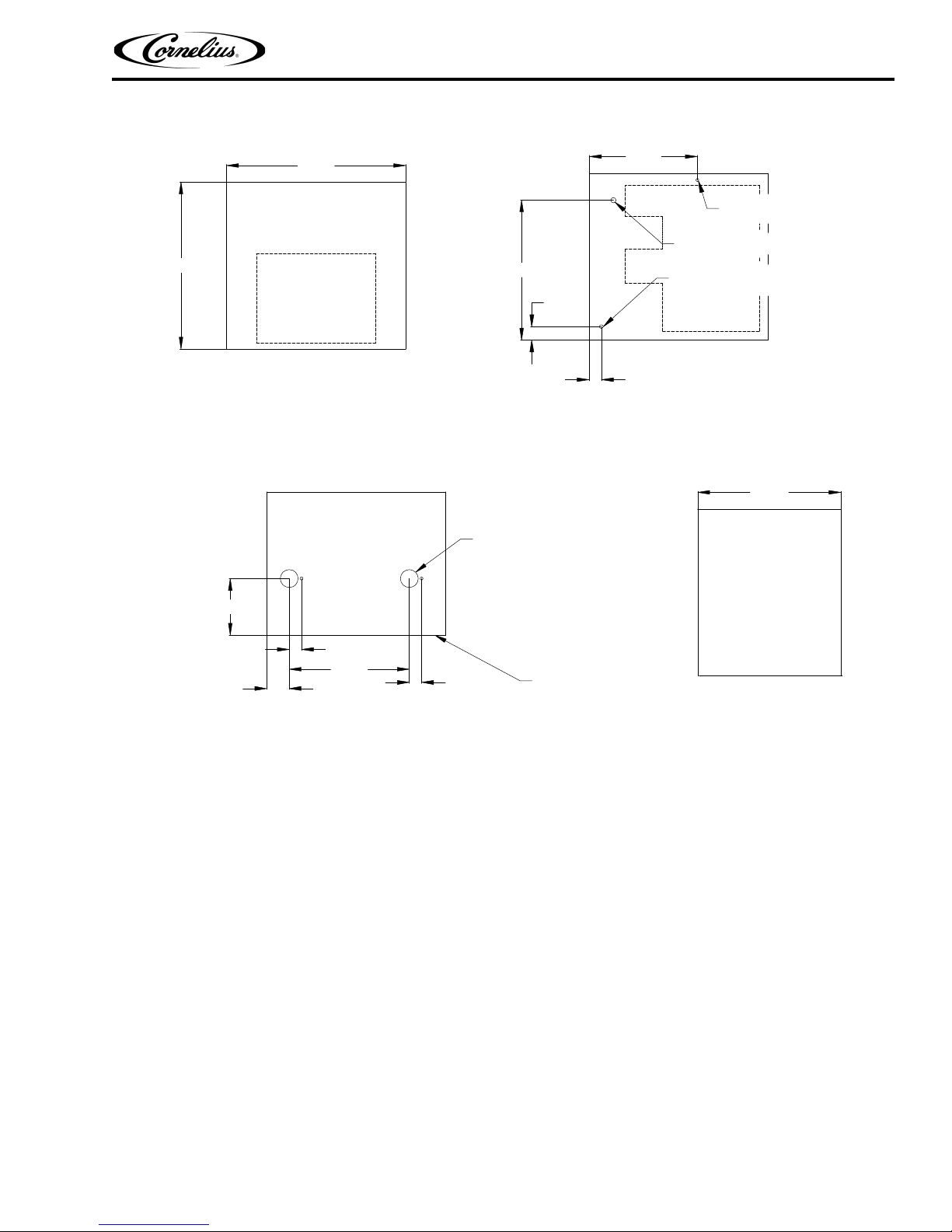
VIEWED FROM BOTTOM OF MACHINE
30.00
24.00
28.06
AIR INLET
SIDE
FRONT
BACK
2.06
2.25
23.50
18.13
WATER IN
ELECTRICAL 7/8 DIA.
DRAIN 3/8 I.D. TUBE
9.50
20.13
3.81
ICE DISCHARGE
2.06
BOTTOM
FRONT
2.06
Continuous Flow Icemaker Service Manual
Figure 3. Series WCC2001-A and WCF2201-A Dimension Drawings
© 2004-2011, IMI Cornelius Inc. - 5 - Publication Number: 630460174SER
Continuous Flow Icemaker Service Manual
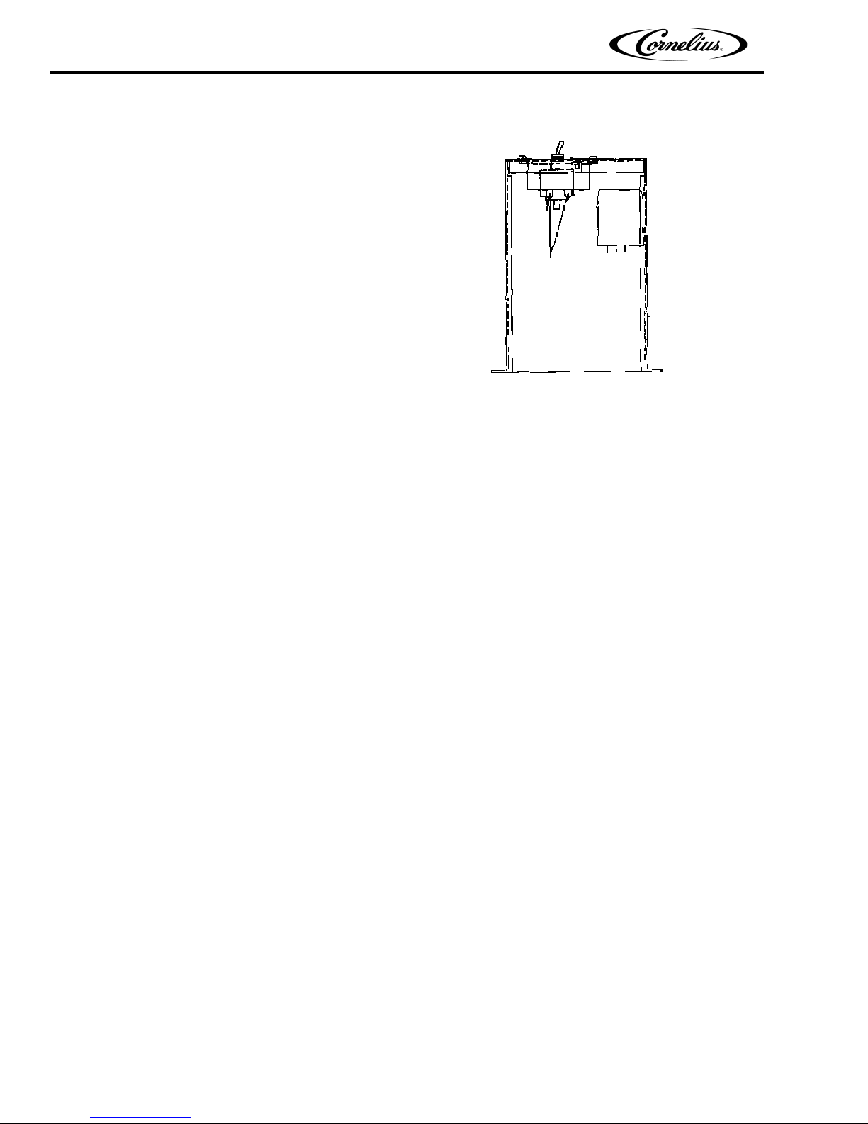
BIN CONTROL
SWITCH TERMINALS
BIN CONTROL
The type of bin control used on all WCC & WCF Models
is an electronic control. The control is supplied with
power to terminals X1 and X2. Terminals X3 and X4 are
a normally closed switch which open when the
thermostat sensor bulb senses ice.
The sensing element is located in a 5/16” stainless steel
ube which hangs from the dispense tray cover down
t
through the center of the drop tube.
To test switch, start the icemaker and block the outlet
. When the ice fills the drop tube about 1/2 full the
tube
icemaker should shut off. When tube is cleared the ice
maker should restart within 5 min.
The Bin control is in electrical series with coil on antifreeze relay along with the low water safety. If unit is water
Figure 4. Bin Control Switch
led, the condenser high pressure cut out is also in series.
coo
The Control Switch is held in place inside electrical box b
y 2 screws. The Control bulb is in the drop tube. It can
be removed by pulling the cable located on the top of the dispense tray cover. When replacing the sensor make
sure the bulb is inserted to the bottom of the thermostat well.
GEARMOTOR
The gearmotor is equipped with a start relay and a manual reset overload.
When current is applied, the relay energizes and completes the circuit to the start winding. The motor reaches a
redetermined speed and the relay drops out, disconnecting the start winding. The run winding remains in the
p
circuit as long as current is applied.
The purpose of the overload is to automatically shut off
transmission, an overload condition within the evaporator or an electrical malfunction. It does this by sensing
amperage draw. If the motor stalls the start relay would energize and stay energized. The amperage would surge 5
to 6 times greater than the normal draw. In this event the overload would shut off the transmission in 4 to 8
seconds.
If the motor is subjected to an abnormal load,
but does not reach a stall condition, the overload will react, but over
a greater period of time. The reaction time depends upon the amperage to which it is subjected.
The overload, through the safety circuit, also shuts off the compressor.
the motor in the event of a mechanical bind of the
Publication Number: 630460174SER - 6 - © 2004-2011, IMI Cornelius Inc.
 Loading...