

Cornelius Viper E 2 Flavor, Viper E 4 Flavor, Viper E 3 Flavor Service Manual
Classic model
Carbon model
VIPER (E) 2 FLAVOR, VIPER (E) 3 FLAVOR
& VIPER (E) 4 FLAVOR
Service Manual
Release Date: November 06, 2008
Publication Number: 621260373SER
Revision Date: May 10, 2016
Revision: N
Visit the Cornelius web site at www.cornelius.com
for all your Literature needs.

The products, technical information, and instructions contained in this manual are subject to change without notice.
These instructions are not intended to cover all details or variations of the equipment, nor to provide for every possi
ble contingency in the installation, operation or maintenance of this equipment. This manual assumes that the person(s) working on the equipment have been trained and are skilled in working with electrical, plumbing, pneumatic,
and mechanical equipment. It is assumed that appropriate safety precautions are taken and that all local safety and
construction requirements are being met, in addition to the information contained in this manual.
This Product is warranted only as provided in Cornelius’ Commercial Warranty applicable to this Product and is subject to all of the restrictions and limitations contained in the Commercial Warranty.
Cornelius will not be responsible for any repair, replacement or other service required by or loss or damage resulting
from any of the following occurrences, including but not limited to, (1) other than normal and proper use and normal
service conditions with respect to the Product, (2) improper voltage, (3) inadequate wiring, (4) abuse, (5) accident,
(6) alteration, (7) misuse, (8) neglect, (9) unauthorized repair or the failure to utilize suitably qualified and trained per
sons to perform service and/or repair of the Product, (10) improper cleaning, (11) failure to follow installation, operating, cleaning or maintenance instructions, (12) use of “non-authorized” parts (i.e., parts that are not 100%
compatible with the Product) which use voids the entire warranty, (13) Product parts in contact with water or the
product dispensed which are adversely impacted by changes in liquid scale or chemical composition.
Contact Information:
To inquire about current revisions of this and other documentation or for assistance with any Cornelius product contact:
www.cornelius.com
800-238-3600
-
-
Trademarks and Copyrights:
This document contains proprietary information and it may not be reproduced in any way without permission from
Cornelius.
This document contains the original instructions for the unit described.
CORNELIUS INC
101 Regency Drive
Glendale Heights, IL
Tel: + 1 800-238-3600
Printed in U.S.A.

TABLE OF CONTENTS
Safety Instructions . . . . . . . . . . . . . . . . . . . . . . . . . . . . . . . . . . . . . . . . . . . . . . . . . . . . . . . . . . . . . . . 1
Read and Follow ALL Safety Instructions . . . . . . . . . . . . . . . . . . . . . . . . . . . . . . . . . . . . . . . . . . . .1
Safety Overview . . . . . . . . . . . . . . . . . . . . . . . . . . . . . . . . . . . . . . . . . . . . . . . . . . . . . . . . . . . . 1
Recognition . . . . . . . . . . . . . . . . . . . . . . . . . . . . . . . . . . . . . . . . . . . . . . . . . . . . . . . . . . . . . . . . 1
Different Types of Alerts . . . . . . . . . . . . . . . . . . . . . . . . . . . . . . . . . . . . . . . . . . . . . . . . . . . . . . . . . 1
Safety Tips . . . . . . . . . . . . . . . . . . . . . . . . . . . . . . . . . . . . . . . . . . . . . . . . . . . . . . . . . . . . . . . . . . . . 1
Qualified Service Personnel . . . . . . . . . . . . . . . . . . . . . . . . . . . . . . . . . . . . . . . . . . . . . . . . . . . . . . 2
Safety Precautions . . . . . . . . . . . . . . . . . . . . . . . . . . . . . . . . . . . . . . . . . . . . . . . . . . . . . . . . . . . . . 2
Shipping And Storage . . . . . . . . . . . . . . . . . . . . . . . . . . . . . . . . . . . . . . . . . . . . . . . . . . . . . . . . . . . 2
Mounting in or on a Counter . . . . . . . . . . . . . . . . . . . . . . . . . . . . . . . . . . . . . . . . . . . . . . . . . . . . . . 2
Cart Information and Mounting . . . . . . . . . . . . . . . . . . . . . . . . . . . . . . . . . . . . . . . . . . . . . . . . . . . . 2
Introduction . . . . . . . . . . . . . . . . . . . . . . . . . . . . . . . . . . . . . . . . . . . . . . . . . . . . . . . . . . . . . . . . . . . . . 3
Manual Overview . . . . . . . . . . . . . . . . . . . . . . . . . . . . . . . . . . . . . . . . . . . . . . . . . . . . . . . . . . . . . . . 3
Dispensed Product Conditions . . . . . . . . . . . . . . . . . . . . . . . . . . . . . . . . . . . . . . . . . . . . . . . . . . . . 4
Overrun, as Applied to Carbonated Beverages . . . . . . . . . . . . . . . . . . . . . . . . . . . . . . . . . . . . . 4
Overrun Definition . . . . . . . . . . . . . . . . . . . . . . . . . . . . . . . . . . . . . . . . . . . . . . . . . . . . . . . . 4
Overrun is a Variable . . . . . . . . . . . . . . . . . . . . . . . . . . . . . . . . . . . . . . . . . . . . . . . . . . . . . .4
Specific Product Ingredients Affect Overrun . . . . . . . . . . . . . . . . . . . . . . . . . . . . . . . . . . . . 4
BRIX Affects Overrun . . . . . . . . . . . . . . . . . . . . . . . . . . . . . . . . . . . . . . . . . . . . . . . . . . . . . 4
Low Dispensing Volume Affects Overrun . . . . . . . . . . . . . . . . . . . . . . . . . . . . . . . . . . . . . . 4
Carbonation Level in Liquid Product Affects Overrun . . . . . . . . . . . . . . . . . . . . . . . . . . . . . 4
Freezing Affects Overrun . . . . . . . . . . . . . . . . . . . . . . . . . . . . . . . . . . . . . . . . . . . . . . . . . . . 4
System Overview . . . . . . . . . . . . . . . . . . . . . . . . . . . . . . . . . . . . . . . . . . . . . . . . . . . . . . . . . . . . . . . . . 5
Introduction . . . . . . . . . . . . . . . . . . . . . . . . . . . . . . . . . . . . . . . . . . . . . . . . . . . . . . . . . . . . . . . . . . . 5
Theory of Operation . . . . . . . . . . . . . . . . . . . . . . . . . . . . . . . . . . . . . . . . . . . . . . . . . . . . . . . . . . . . . 5
CO2 System . . . . . . . . . . . . . . . . . . . . . . . . . . . . . . . . . . . . . . . . . . . . . . . . . . . . . . . . . . . . . . 12
Water System . . . . . . . . . . . . . . . . . . . . . . . . . . . . . . . . . . . . . . . . . . . . . . . . . . . . . . . . . . . . . 17
Syrup System . . . . . . . . . . . . . . . . . . . . . . . . . . . . . . . . . . . . . . . . . . . . . . . . . . . . . . . . . . . . . 17
Control Panel . . . . . . . . . . . . . . . . . . . . . . . . . . . . . . . . . . . . . . . . . . . . . . . . . . . . . . . . . . . . . . . . . 17
Introduction . . . . . . . . . . . . . . . . . . . . . . . . . . . . . . . . . . . . . . . . . . . . . . . . . . . . . . . . . . . . . . . 17
Control Panel Display . . . . . . . . . . . . . . . . . . . . . . . . . . . . . . . . . . . . . . . . . . . . . . . . . . . . 17
Control Panel Buttons . . . . . . . . . . . . . . . . . . . . . . . . . . . . . . . . . . . . . . . . . . . . . . . . . . . . 18
Control Panel Menu Descriptions . . . . . . . . . . . . . . . . . . . . . . . . . . . . . . . . . . . . . . . . . . . . . . . . . 19
System Menus . . . . . . . . . . . . . . . . . . . . . . . . . . . . . . . . . . . . . . . . . . . . . . . . . . . . . . . . . . . . . 19
Main Menu . . . . . . . . . . . . . . . . . . . . . . . . . . . . . . . . . . . . . . . . . . . . . . . . . . . . . . . . . . . . . . . . 20
Unit Data Menu . . . . . . . . . . . . . . . . . . . . . . . . . . . . . . . . . . . . . . . . . . . . . . . . . . . . . . . . .21
Error Status Menu . . . . . . . . . . . . . . . . . . . . . . . . . . . . . . . . . . . . . . . . . . . . . . . . . . . . . . .21
Error Log Menu . . . . . . . . . . . . . . . . . . . . . . . . . . . . . . . . . . . . . . . . . . . . . . . . . . . . . . . . .23
Setup Menu . . . . . . . . . . . . . . . . . . . . . . . . . . . . . . . . . . . . . . . . . . . . . . . . . . . . . . . . . . . . . . . 24
Clock Setup Menu . . . . . . . . . . . . . . . . . . . . . . . . . . . . . . . . . . . . . . . . . . . . . . . . . . . . . . . 24
Setting the Clock . . . . . . . . . . . . . . . . . . . . . . . . . . . . . . . . . . . . . . . . . . . . . . . . . . . . . . 25
Setting Daylight Savings Time . . . . . . . . . . . . . . . . . . . . . . . . . . . . . . . . . . . . . . . . . . . . 25
Events Setup Menu . . . . . . . . . . . . . . . . . . . . . . . . . . . . . . . . . . . . . . . . . . . . . . . . . . . . . . 27
Setting Events . . . . . . . . . . . . . . . . . . . . . . . . . . . . . . . . . . . . . . . . . . . . . . . . . . . . . . . . . . 27

Setting the Sleep and Wake up Times . . . . . . . . . . . . . . . . . . . . . . . . . . . . . . . . . . . . . . . 27
Setting Defrost Lockout . . . . . . . . . . . . . . . . . . . . . . . . . . . . . . . . . . . . . . . . . . . . . . . . . 28
Viscosity Setup Menu . . . . . . . . . . . . . . . . . . . . . . . . . . . . . . . . . . . . . . . . . . . . . . . . . . . . 29
Options Setup Menu . . . . . . . . . . . . . . . . . . . . . . . . . . . . . . . . . . . . . . . . . . . . . . . . . . . . . 29
Setting the Temperature Format . . . . . . . . . . . . . . . . . . . . . . . . . . . . . . . . . . . . . . . . . . 30
Setting the Date Format . . . . . . . . . . . . . . . . . . . . . . . . . . . . . . . . . . . . . . . . . . . . . . . . 30
Setting the Time Format . . . . . . . . . . . . . . . . . . . . . . . . . . . . . . . . . . . . . . . . . . . . . . . . 30
Setting the POS Lighting . . . . . . . . . . . . . . . . . . . . . . . . . . . . . . . . . . . . . . . . . . . . . . . . 30
Setting the Type of Syrup . . . . . . . . . . . . . . . . . . . . . . . . . . . . . . . . . . . . . . . . . . . . . . . 30
Maintenance Menu . . . . . . . . . . . . . . . . . . . . . . . . . . . . . . . . . . . . . . . . . . . . . . . . . . . . . . . . . 30
Barrel Maintenance Menu . . . . . . . . . . . . . . . . . . . . . . . . . . . . . . . . . . . . . . . . . . . . . . . . . 31
Purging a Barrel . . . . . . . . . . . . . . . . . . . . . . . . . . . . . . . . . . . . . . . . . . . . . . . . . . . . . . 31
Filling a Barrel . . . . . . . . . . . . . . . . . . . . . . . . . . . . . . . . . . . . . . . . . . . . . . . . . . . . . . . . 32
Run the Barrel Motor . . . . . . . . . . . . . . . . . . . . . . . . . . . . . . . . . . . . . . . . . . . . . . . . . . . 32
Rinsing a Barrel . . . . . . . . . . . . . . . . . . . . . . . . . . . . . . . . . . . . . . . . . . . . . . . . . . . . . . . 32
Manual Diagnostic Menu . . . . . . . . . . . . . . . . . . . . . . . . . . . . . . . . . . . . . . . . . . . . . . . . . 33
Totals Menu . . . . . . . . . . . . . . . . . . . . . . . . . . . . . . . . . . . . . . . . . . . . . . . . . . . . . . . . . . . 34
BRIX Setup Menu . . . . . . . . . . . . . . . . . . . . . . . . . . . . . . . . . . . . . . . . . . . . . . . . . . . . . . . 34
Motor Setup Menu . . . . . . . . . . . . . . . . . . . . . . . . . . . . . . . . . . . . . . . . . . . . . . . . . . . . . . 37
Calibrating a Motor . . . . . . . . . . . . . . . . . . . . . . . . . . . . . . . . . . . . . . . . . . . . . . . . . . . . 38
System Menu . . . . . . . . . . . . . . . . . . . . . . . . . . . . . . . . . . . . . . . . . . . . . . . . . . . . . . . . . . 39
Security . . . . . . . . . . . . . . . . . . . . . . . . . . . . . . . . . . . . . . . . . . . . . . . . . . . . . . . . . . . . . . . 39
Pressure Sensors . . . . . . . . . . . . . . . . . . . . . . . . . . . . . . . . . . . . . . . . . . . . . . . . . . . . . . . 40
Operation . . . . . . . . . . . . . . . . . . . . . . . . . . . . . . . . . . . . . . . . . . . . . . . . . . . . . . . . . . . . . . . . . . . . . . 41
Maintaining Product Quality . . . . . . . . . . . . . . . . . . . . . . . . . . . . . . . . . . . . . . . . . . . . . . . . . . . . . 41
Dispensed Product Throughput . . . . . . . . . . . . . . . . . . . . . . . . . . . . . . . . . . . . . . . . . . . . . . . 41
Programmed Defrost Scheduling . . . . . . . . . . . . . . . . . . . . . . . . . . . . . . . . . . . . . . . . . . . . . . 41
Sleep Mode Recommendations . . . . . . . . . . . . . . . . . . . . . . . . . . . . . . . . . . . . . . . . . . . . 41
Viscosity Setting . . . . . . . . . . . . . . . . . . . . . . . . . . . . . . . . . . . . . . . . . . . . . . . . . . . . . . . . . . . 42
Starting the Unit . . . . . . . . . . . . . . . . . . . . . . . . . . . . . . . . . . . . . . . . . . . . . . . . . . . . . . . . . . . . . . 42
Preventative Maintenance . . . . . . . . . . . . . . . . . . . . . . . . . . . . . . . . . . . . . . . . . . . . . . . . . . . . . . . . 43
Summary . . . . . . . . . . . . . . . . . . . . . . . . . . . . . . . . . . . . . . . . . . . . . . . . . . . . . . . . . . . . . . . . . . . 43
Monthly Maintenance . . . . . . . . . . . . . . . . . . . . . . . . . . . . . . . . . . . . . . . . . . . . . . . . . . . . . . . . . . 43
Cleaning Air Filter . . . . . . . . . . . . . . . . . . . . . . . . . . . . . . . . . . . . . . . . . . . . . . . . . . . . . . . . . . 43
Semi-Annual Maintenance . . . . . . . . . . . . . . . . . . . . . . . . . . . . . . . . . . . . . . . . . . . . . . . . . . . . . . 44
Inspecting and Replacing Scraper Blades . . . . . . . . . . . . . . . . . . . . . . . . . . . . . . . . . . . . . . . 44
Cleaning the Syrup Connections . . . . . . . . . . . . . . . . . . . . . . . . . . . . . . . . . . . . . . . . . . . . . . 45
Servicing Motorman Dispensing Valves . . . . . . . . . . . . . . . . . . . . . . . . . . . . . . . . . . . . . . . . . 45
Sanitizing the System . . . . . . . . . . . . . . . . . . . . . . . . . . . . . . . . . . . . . . . . . . . . . . . . . . . . . . . 47
Emptying a Barrel . . . . . . . . . . . . . . . . . . . . . . . . . . . . . . . . . . . . . . . . . . . . . . . . . . . . . . . 47
Flushing the System of Syrup . . . . . . . . . . . . . . . . . . . . . . . . . . . . . . . . . . . . . . . . . . . . 47
Sanitizing the Barrel . . . . . . . . . . . . . . . . . . . . . . . . . . . . . . . . . . . . . . . . . . . . . . . . . . . . . 48
Flushing the System . . . . . . . . . . . . . . . . . . . . . . . . . . . . . . . . . . . . . . . . . . . . . . . . . . . . . 49

Cleaning the Water Filter . . . . . . . . . . . . . . . . . . . . . . . . . . . . . . . . . . . . . . . . . . . . . . . . . . . . . 50
Component Replacement . . . . . . . . . . . . . . . . . . . . . . . . . . . . . . . . . . . . . . . . . . . . . . . . . . . . . . . . . 51
Barrel Motor Seal Replacement . . . . . . . . . . . . . . . . . . . . . . . . . . . . . . . . . . . . . . . . . . . . . . . . . . 51
Removing the Existing Seal . . . . . . . . . . . . . . . . . . . . . . . . . . . . . . . . . . . . . . . . . . . . . . . . . . .51
Installing a New Seal . . . . . . . . . . . . . . . . . . . . . . . . . . . . . . . . . . . . . . . . . . . . . . . . . . . . . . . . 51
Motor Seal Leak Test . . . . . . . . . . . . . . . . . . . . . . . . . . . . . . . . . . . . . . . . . . . . . . . . . . . . . . . 53
Barrel Motor Replacement . . . . . . . . . . . . . . . . . . . . . . . . . . . . . . . . . . . . . . . . . . . . . . . . . . . . . . . 53
Motor Run Capacitor Replacement . . . . . . . . . . . . . . . . . . . . . . . . . . . . . . . . . . . . . . . . . . . . . . . . 54
Water Pump Replacement . . . . . . . . . . . . . . . . . . . . . . . . . . . . . . . . . . . . . . . . . . . . . . . . . . . . . . 55
CO2 Shutoff Solenoid Replacement . . . . . . . . . . . . . . . . . . . . . . . . . . . . . . . . . . . . . . . . . . . . . . . 56
Syrup and Water Shutoff Solenoid Replacement . . . . . . . . . . . . . . . . . . . . . . . . . . . . . . . . . . . . . 56
CO2 Regulator Replacement . . . . . . . . . . . . . . . . . . . . . . . . . . . . . . . . . . . . . . . . . . . . . . . . . . . . 57
Condenser Fan Motor Replacement . . . . . . . . . . . . . . . . . . . . . . . . . . . . . . . . . . . . . . . . . . . . . . . 58
Compressor Replacement . . . . . . . . . . . . . . . . . . . . . . . . . . . . . . . . . . . . . . . . . . . . . . . . . . . . . . . 59
Hot Gas Solenoid Replacement . . . . . . . . . . . . . . . . . . . . . . . . . . . . . . . . . . . . . . . . . . . . . . . . . .59
Liquid Line Solenoid Replacement . . . . . . . . . . . . . . . . . . . . . . . . . . . . . . . . . . . . . . . . . . . . . . . .60
Syrup Pressure Switch Replacement . . . . . . . . . . . . . . . . . . . . . . . . . . . . . . . . . . . . . . . . . . . . . . 60
Water Pressure Switch Replacement . . . . . . . . . . . . . . . . . . . . . . . . . . . . . . . . . . . . . . . . . . . . . . 61
Display Board Replacement . . . . . . . . . . . . . . . . . . . . . . . . . . . . . . . . . . . . . . . . . . . . . . . . . . . . . 62
Control Board Replacement . . . . . . . . . . . . . . . . . . . . . . . . . . . . . . . . . . . . . . . . . . . . . . . . . . . . . 62
Backward/Forward Compatibility with Older Software Versions . . . . . . . . . . . . . . . . . . . . . . . 63
Motor Board Replacement . . . . . . . . . . . . . . . . . . . . . . . . . . . . . . . . . . . . . . . . . . . . . . . . . . . . . . . 64
Troubleshooting . . . . . . . . . . . . . . . . . . . . . . . . . . . . . . . . . . . . . . . . . . . . . . . . . . . . . . . . . . . . . . . . 66
Troubleshooting the System . . . . . . . . . . . . . . . . . . . . . . . . . . . . . . . . . . . . . . . . . . . . . . . . . . . . . 66
Troubleshooting Product Not Cold . . . . . . . . . . . . . . . . . . . . . . . . . . . . . . . . . . . . . . . . . . . . . . . .66

Viper Service Manual
!
DANGER:
!
WARNING:
CAUTION:
!
!
SAFETY INSTRUCTIONS
READ AND FOLLOW ALL SAFETY INSTRUCTIONS
Safety Overview
• Read and follow ALL SAFETY INSTRUCTIONS in this manual and any warning/caution labels on the unit (decals,
labels or laminated cards).
• Read and understand ALL applicable OSHA (Occupational Safety and Health Administration) safety regulations before
operating this unit.
Recognition
Recognize Safety Alerts
This is the safety alert symbol. When you see it in this manual or on the unit,
be alert to the potential of personal injury or damage to the unit.
DIFFERENT TYPES OF ALERTS
Indicates an immediate hazardous situation, which if not avoided, WILL result in serious injury, death or equipment
damage.
Indicates a potentially hazardous situation, which if not avoided, COULD result in serious injury, death, or equipment
damage.
Indicates a potentially hazardous situation, which if not avoided, MAY result in minor or moderate injury or
equipment damage.
SAFETY TIPS
• Carefully read and follow all safety messages in this manual and safety signs on the unit.
• Keep safety signs in good condition and replace missing or damaged items.
• Learn how to operate the unit and how to use the controls properly.
• Do not let anyone operate the unit without proper training. This appliance is not intended for use by very young children
or infirm persons without supervision. Young children should be supervised to ensure that they do not play with the
appliance.
• Keep your unit in proper working condition and do not allow unauthorized modifications to the unit.
NOTE: The dispenser is not designed for a wash-down environment and MUST NOT be placed in an
area where a water jet could be used.
© 2008-2016, Cornelius Inc. - 1 - Publication Number: 621260373SER
Viper Service Manual
!
WARNING:
!
WARNING:
CAUTION:
!
!
WARNING:
!
WARNING:
QUALIFIED SERVICE PERSONNEL
Only trained and certified electrical, plumbing and refrigeration technicians should service this unit. ALL WIRING
AND PLUMBING MUST CONFORM TO NATIONAL AND LOCAL CODES. FAILURE TO COMPLY COULD
RESULT IN SERIOUS INJURY, DEATH OR EQUIPMENT DAMAGE.
IF THE SUPPLY CORD IS DAMAGED, IT MUST BE REPLACED BY THE MANUFACTURER, ITS SERVICE
AGENT OR SIMILARLY QUALIFIED PERSONS IN ORDER TO AVOID A HAZARD.
SAFETY PRECAUTIONS
This unit has been specifically designed to provide protection against personal injury. To ensure continued
protection observe the following:
Disconnect power to the unit before servicing following all lock out/tag out procedures established by the user. Verify
all of the power is off to the unit before any work is performed.
Failure to disconnect the power could result in serious injury, death or equipment damage.
Always be sure to keep area around the unit clean and free of clutter. Failure to keep this area clean may result in
injury or equipment damage.
SHIPPING AND STORAGE
Before shipping, storing, or relocating the unit, the unit must be sanitized and all sanitizing solution must be
drained from the system. A freezing ambient environment will cause residual sanitizing solution or water
remaining inside the unit to freeze resulting in damage to internal components.
MOUNTING IN OR ON A COUNTER
When installing the unit in or on a counter top, the counter must be able to support a weight in excess of 450 lbs. to
insure adequate support for the unit.
Failure To Comply Could Result In Serious Injury, Death Or Equipment Damage.
NOTE: Many units incorporate the use of additional equipment such as ice makers. When any
addition equipment is used you must check with the equipment manufacturer to determine
the additional weight the counter will need to support to ensure a safe installation.
CART INFORMATION AND MOUNTING
These carts are also designed with movable wheels that act as outriggers to provide stability to the unit when it is
being moved.
The above listed mounting bolts must be installed and the wheels extended and locked in the outboard position prior
to moving the unit.
Failure to comply could result in serious injury, death or equipment damage.
Publication Number: 621260373SER - 2 - © 2008-2016, Cornelius Inc.

Viper Service Manual
INTRODUCTION
MANUAL OVERVIEW
The organization of this manual allows the user to scan quickly to the subject of interest along the left side of a
page and to read the detail about the subject or procedure on the right side of the page. The manual provides the
detail needed for newcomers to the industry while allowing experienced technicians to skip over the details and
move quickly through the material.
This manual is designed as a guide to the technician in maintaining and servicing the Viper system. The Viper
system is simple in design and has built-in features and diagnostic controls to help the service technician quickly
and accurately service the machine.
The unit consists of multiple freeze barrels that each contain an internal beater driven by a rear mounted electric
motor, a refrigeration system, timer-controlled, automatic hot gas defrost system and interconnecting tubing and
controls required to dispense the product.
Some of the system features and functions are listed below:
• Simple User Interface LCD Display
• Real Time Clock
• Incoming Line Voltage Sensing
• Pressure Sensing of Incoming Water, Syrup and CO
2
• System Error Handling
• Error Log
• Viscosity Control
© 2008-2016, Cornelius Inc. - 3 - Publication Number: 621260373SER
Viper Service Manual
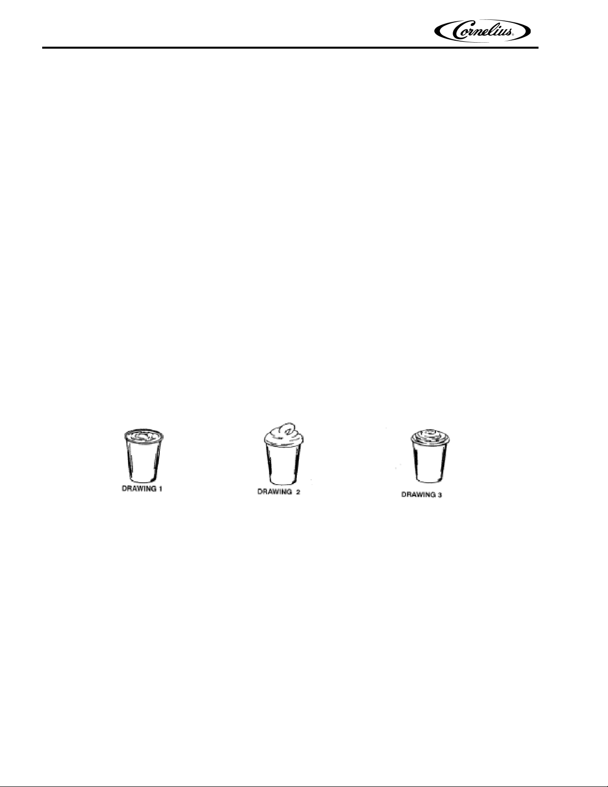
DISPENSED PRODUCT CONDITIONS
Overrun, as Applied to Carbonated Beverages
Overrun Definition
Overrun is defined as product expansion that takes place in the frozen carbonated drink. It is caused primarily by
gas breakout and secondarily by freezing.
CO
2
Overrun is a Variable
The percentage or degree of overrun depends on a number of factors. The specific syrup, BRIX, low dispensing
volume, carbonation level in the liquid product and freezing of the product. These items all affect overrun. After
these factors have been considered, desired viscosity (product consistency) adjustment may be made on the
unit. The viscosity adjustment adjusts product texture from very wet to light.
Specific Product Ingredients Affect Overrun
Each syrup has its own specific formulation of makeup. Fruit flavors contain citric acids that colas do not. Colas
also differ in ingredients from one brand to another. Each product formulation has its own peculiarities regarding
the way the product absorbs carbonation and the way it releases carbonation.
BRIX Affects Overrun
Sugar in carbonated drinks is like anti-freeze in water. The higher the BRIX, the greater the resistance of the
product to freezing. Conversely, in products with lower BRIX, freezing takes place at higher temperatures than for
high-BRIX products. Thus, BRIX affects overrun because the amount of sugar in a drink has a direct bearing on
the product’s freezing characteristics.
Low Dispensing Volume Affects Overrun
When a unit sits idle for a period of time with no drinks being dispensed, CO2 gas in the system takes a “set”.
When the first few drinks are drawn off after an idle period, CO
is dispensed. The result is that these first drinks have less overrun than drinks dispensed during peak-use
periods.
2 gas has less tendency to break out as the drink
Carbonation Level in Liquid Product Affects Overrun
The higher the specific carbonation level in a given product, the greater the potential for carbonation breakout in
frozen carbonated form of that drink. For example, drinks with 3.0 volume of carbonation have more gas breakout
in frozen carbonated form and more overrun than drinks that contain 2.0 volumes of CO
2 gas.
Freezing Affects Overrun
Freezing causes approximately a 5-7 percent expansion in dispensed frozen carbonated drinks. The degree of
freezing is limited because the finished drink is intended to be sipped through a straw. This is not possible if the
product is too “solid”.
Publication Number: 621260373SER - 4 - © 2008-2016, Cornelius Inc.

Viper Service Manual
SYSTEM OVERVIEW
INTRODUCTION
The Viper unit consists of the following systems and hardware:
Multiple freeze barrels, each containing an internal scraper bar driven by an AC motor.
A refrigeration system and an intelligent, hot gas defrost system.
The components are enclosed in a powder-coated steel frame to prevent corrosion. It is covered with ventilated
cladding panels and a lighted merchandiser. The cladding is easily removable to facilitate installation, service and
maintenance.
Each barrel has a transparent faceplate, with an integral relief valve and a removable, self-closing dispensing valve
mounted on the front. A removable drip tray, with cup rest is located directly below the dispensing valves.
A programmable control system with a control panel that controls operational and diagnostic functions and settings
is located behind the merchandiser.
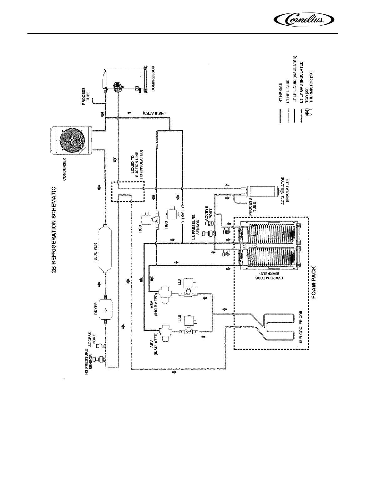
THEORY OF OPERATION
The refrigeration system schematic is shown in Figure 1.. It provides the basic configuration for the Viper
refrigeration system.
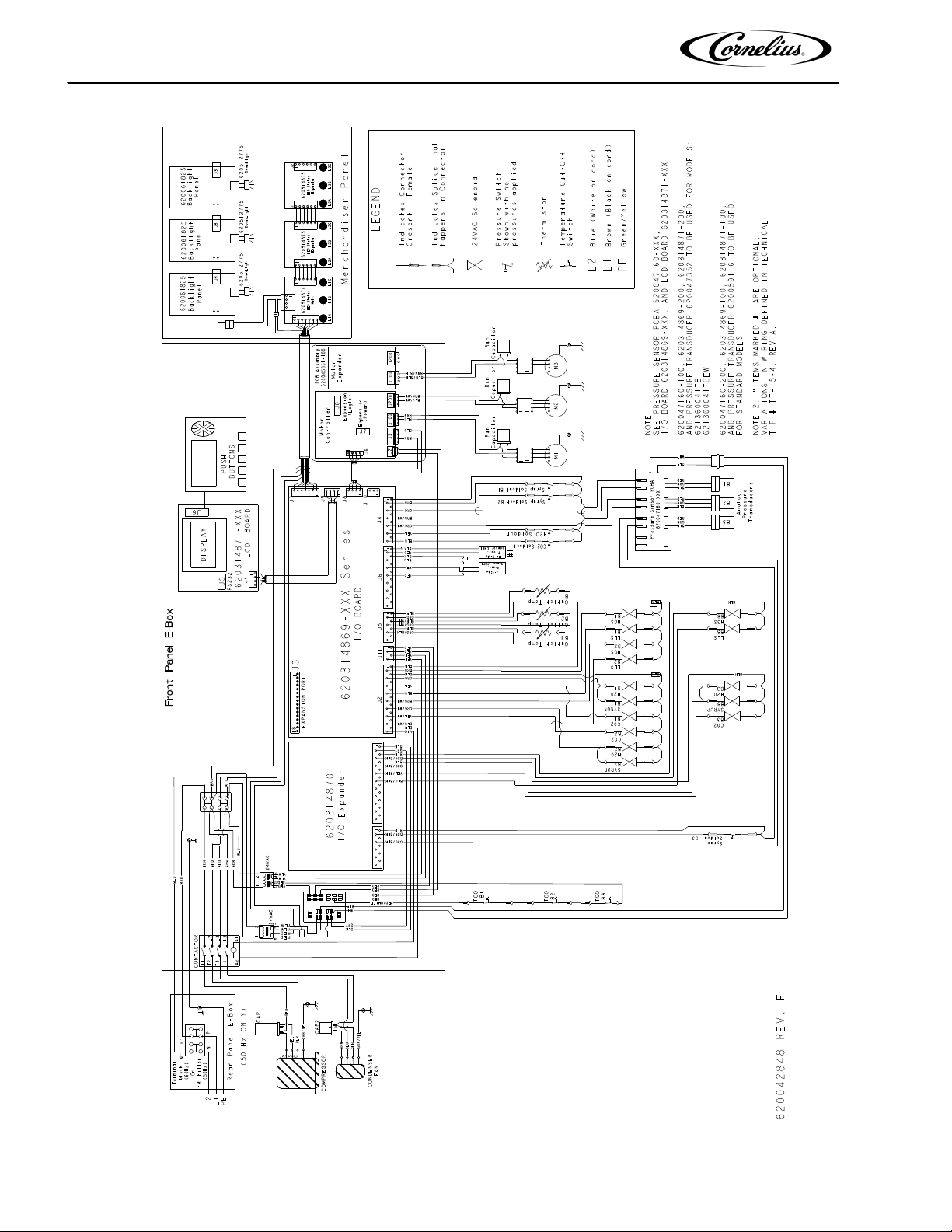
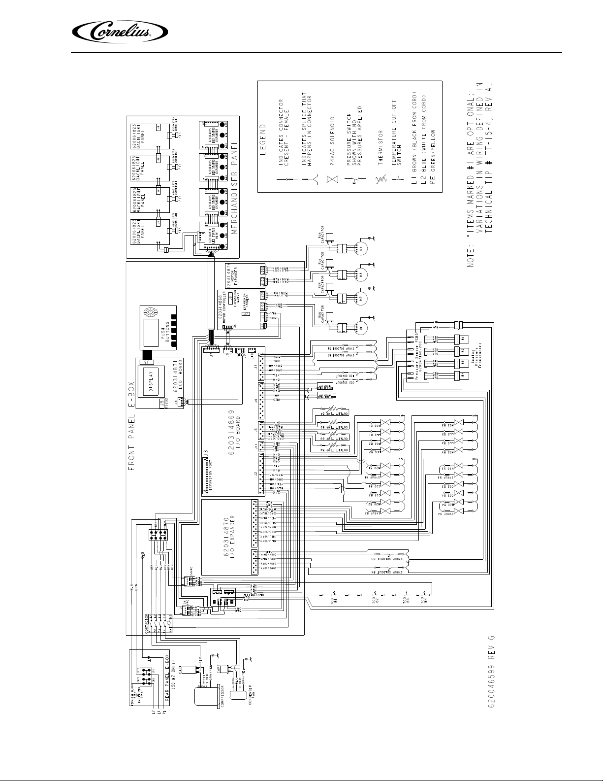
The wiring diagram of the 2-Barrel Viper unit is shown in Figure 4, the wiring diagram of the 3-Barrel Viper unit is
shown in Figure 4. and the wiring diagram of the 4-Barrel Viper unit is shown in Figure 5.. These diagrams show the
details of the electrical connections in the unit.
© 2008-2016, Cornelius Inc. - 5 - Publication Number: 621260373SER
Viper Service Manual
Figure 1. Viper System 2-Barrel Refrigeration Schematic
Publication Number: 621260373SER - 6 - © 2008-2016, Cornelius Inc.
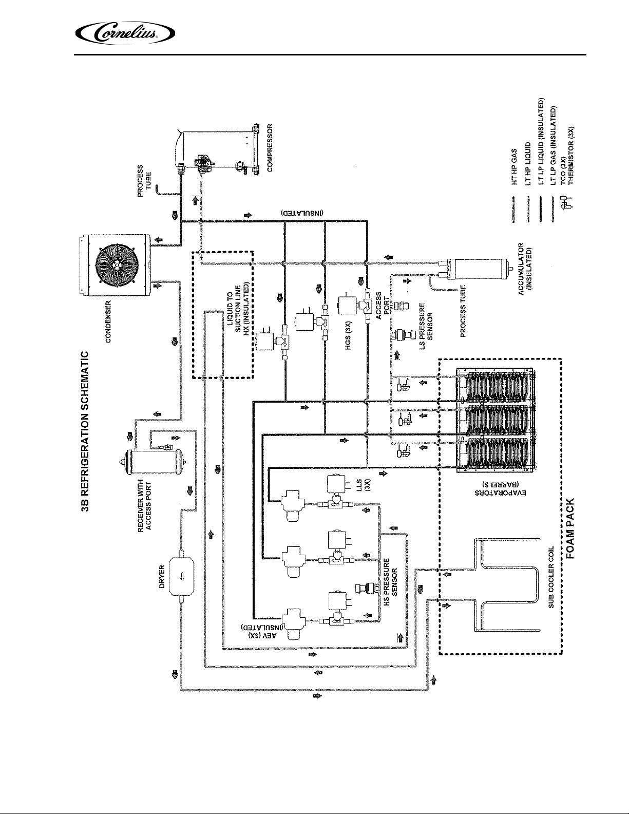
Viper Service Manual
Figure 2. Viper System 3-Barrel Refrigeration Schematic
© 2008-2016, Cornelius Inc. - 7 - Publication Number: 621260373SER
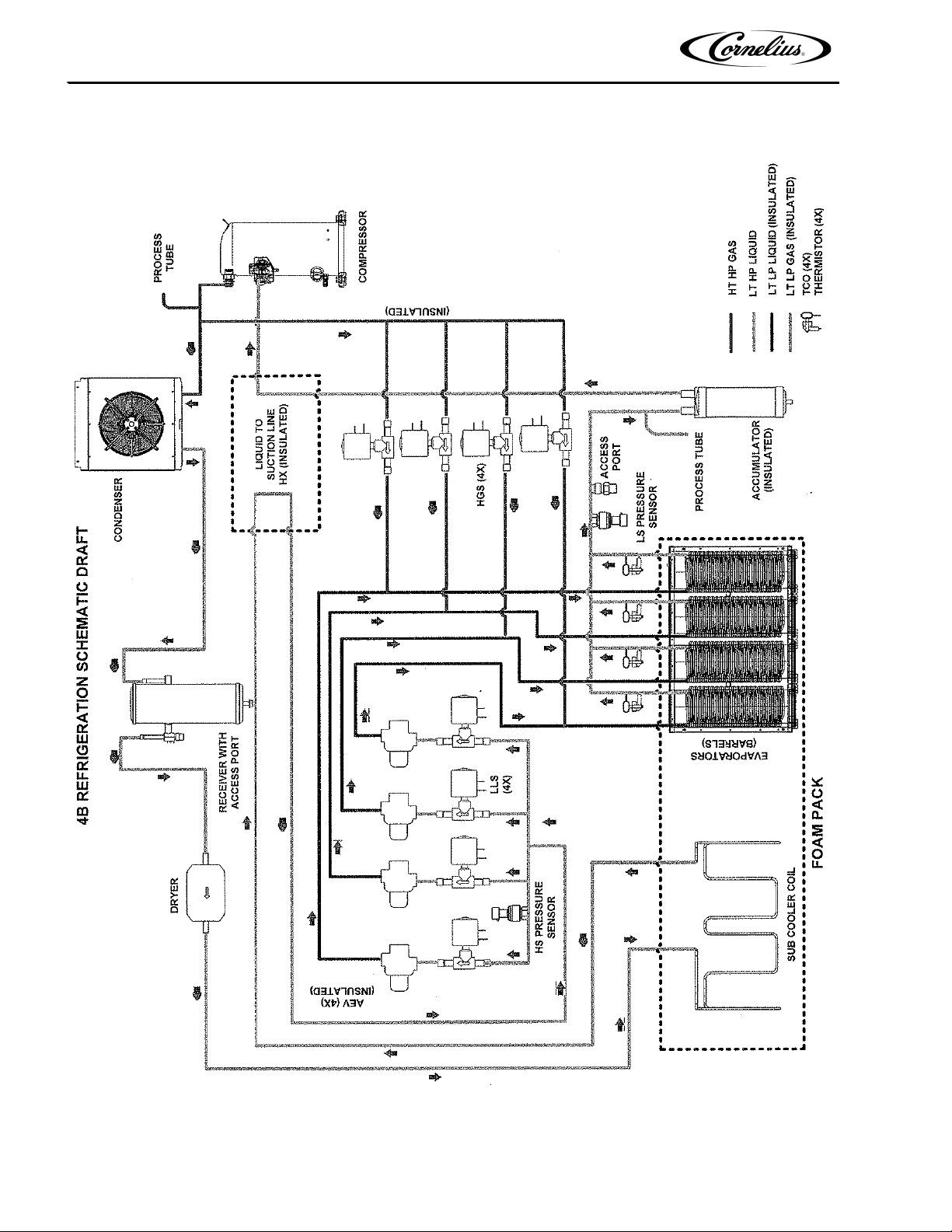
Viper Service Manual
Figure 3. Viper System 4-Barrel Refrigeration Schematic
Publication Number: 621260373SER - 8 - © 2008-2016, Cornelius Inc.
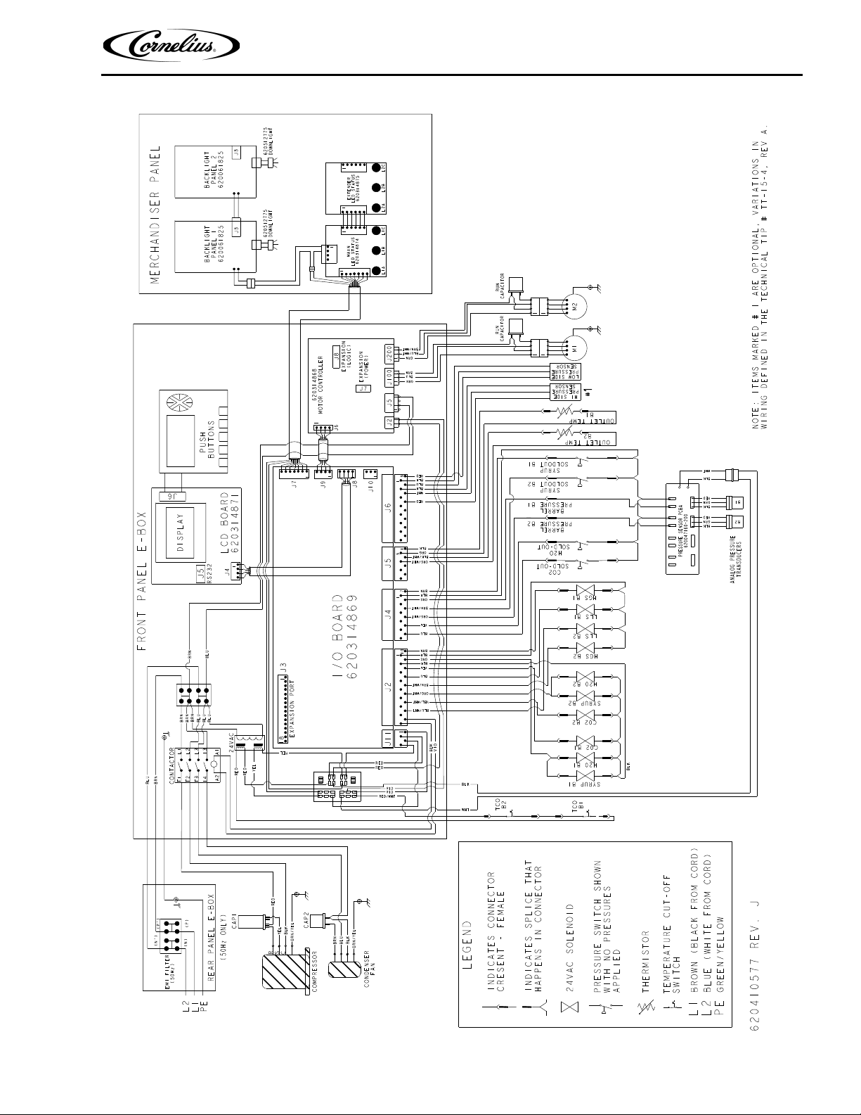
Viper Service Manual
Figure 4. Viper 2-Barrel Wiring Diagram (W/Transducer)
© 2008-2016, Cornelius Inc. - 9 - Publication Number: 621260373SER
Viper Service Manual
Figure 5. Viper 3-Barrel Wiring Diagram
Publication Number: 621260373SER - 10 - © 2008-2016, Cornelius Inc.
Viper Service Manual
Figure 6. Viper 4-Barrel Wiring Diagram
© 2008-2016, Cornelius Inc. - 11 - Publication Number: 621260373SER
Viper Service Manual
FCB Unit
ylppuS2OC
BIB Syrup
BIB Syrup
BIB Pump
C
E
D
A
F
I
Water Filter
Connections
Tubing
1/2 Inch Beverage Tubing
3/8 Inch Beverage Tubing
1/4 Inch Beverage Tubing
3/8 Inch Tygon Tubing
A
B
C
D
E
F
1/2 Inch Hose Barb to 3/4 NPT
1/4 Inch Female Flare Nut and Barb (1/4)
Direct Connection to Syrup
Outlet on Syrup Pump
Direct Connection to CO2
Inlet on Syrup Pump
Direct Connection to Syrup
Inlet on Syrup Pump
1/2 to 3/8 Inch Fitting Reducer
Water Inlet
Syrup Line 1
Syrup Line 2
CO2 Inlet
BIB Syrup
BIB Syrup BIB Pump
C
E
D
G
BIB Pump
C
E
D
BIB Pump
C
E
D
Syrup Line 3
Syrup Line 4
G
¼ Inch Cross Barb
K
H
J
H
CO2 Regulator
I
3/8 Inch TEE Barb
J
3/8 Inch Flare Nut and Barb (3/8)
K
3/8 to 1/4 Inch Fitting Reducer
H
H
B
Max 3 Feet
J
K
K
K
K
F
3 Feet Typical
115 Psig
75 Psig
75 Psig
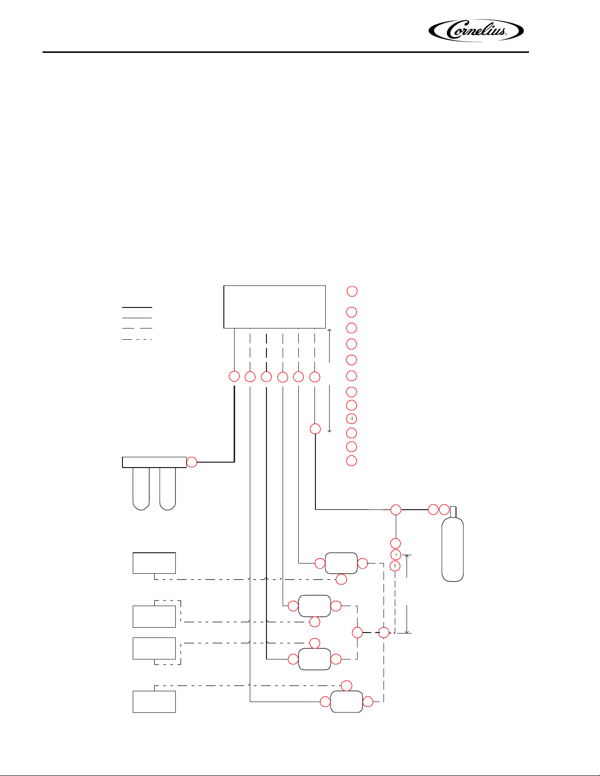
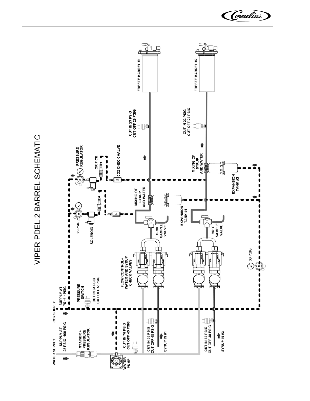
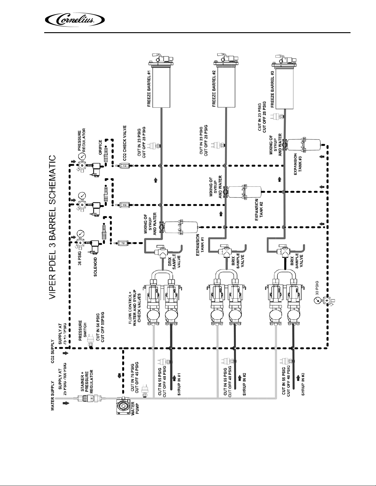
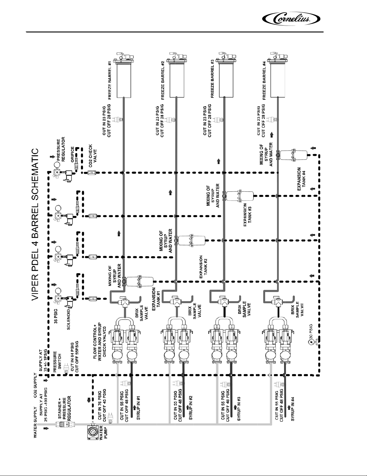
An overall schematic of the three delivery systems contained in the unit are shown in Figure 8., Figure 9. and Figure
10. The CO
diagram. The CO
2 system is on top, the water system is in the middle and the syrup system is at the bottom of the
2 system interacts with both the water and syrup systems. It provides pressure and carbonation for
the syrup/water product mix.
CO2 System
A CO2 tank or bulk CO2 supply delivers carbon dioxide gas (CO2) to an adjustable secondary CO2 regulator
assembly that is attached to the tank as shown in Figure 7. The CO
pump, the expansion tank regulator and the secondary CO
2 enters the expansion tank regulator and is reduced to approximately 30 psig to feed holding pressure on the
CO
2 tank regulators.
expansion tank. This provides a force to work against the barrel pressure when the product freezes and expands.
2 also enters the secondary regulators. These regulators are used to adjust barrel overrun/expansion for various
CO
products. The pressure settings for various types of syrup are shown in Table 1.. Overrun CO
the CO
From the in-line check valve, the CO
2 control solenoids through preset orifices and on to the in-line check valves.
2 flows into the product line.
2 system also supplies CO2 to the water boost
2 pressure is applied to
Publication Number: 621260373SER - 12 - © 2008-2016, Cornelius Inc.
Figure 7. Cylinder CO2 Connection
Viper Service Manual
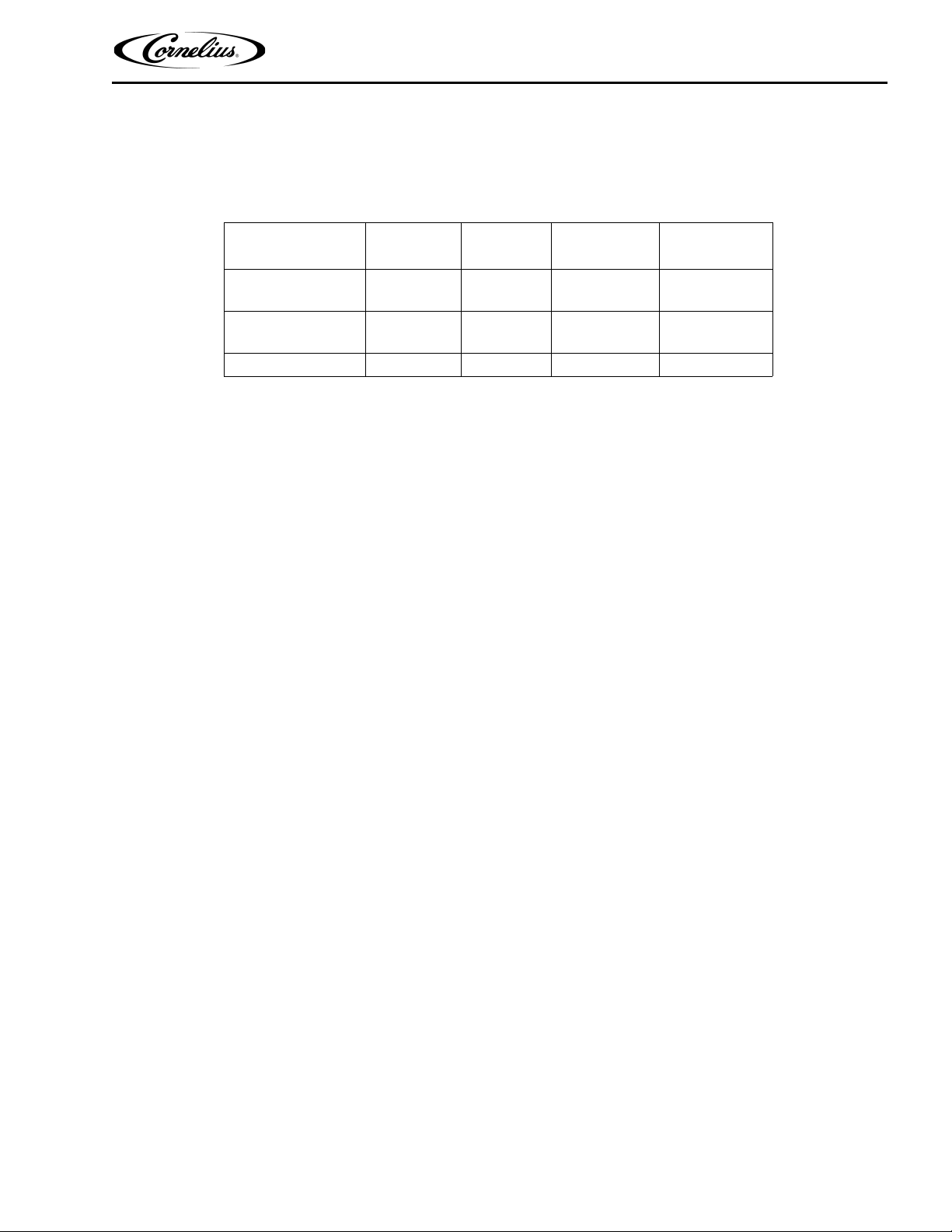
Table 1. provides guidelines for machine settings based on general syrup type. Several factors, including syrup
formulation, level of citric acids, etc, will impact settings. These settings are to provide initial adjustments to achieve
product overruns in the 80-120% range.
Table 1.
Syrup Type
FCB Syrup w/
Foaming Agent
FCB Syrup w/o
Foaming Agent
FUB FUB 7 N/A 30
Syrup Type
Set
FCB 4 34-36 PSIG 30
FCB 4 32-36 PSIG 30
Viscosity Pressure Expansion
NOTE: For citric syrups, adjust the CO2 pressures down by 2-4 PSIG from the above to compensate
for the lower CO
2 adsorption.
© 2008-2016, Cornelius Inc. - 13 - Publication Number: 621260373SER
Viper Service Manual
Figure 8. 2-Barrel System Schematic
Publication Number: 621260373SER - 14 - © 2008-2016, Cornelius Inc.
Viper Service Manual
Figure 9. 3-Barrel System Schematic
© 2008-2016, Cornelius Inc. - 15 - Publication Number: 621260373SER
Viper Service Manual
Figure 10. 4-Barrel System Schematic
Publication Number: 621260373SER - 16 - © 2008-2016, Cornelius Inc.

Viper Service Manual
Water System
Incoming water flows to a water pressure regulator that is preset to 30 psig. It flows through the water booster pump,
to the regulator and through a sold-out switch.
Once through the boost pump, the water supply is split to each barrel and is fed to the water flow controls. From the
flow rate control, the water passes through a single ball check valve and mixes with the syrup in a wye fitting for
injection into the freeze barrel.
Syrup System
Syrup enters the unit through a sold-out switch. It enters a similar flow control to the water system, passes through a
single-ball check valve and into the wye fitting where it meets the water for injection into the freeze barrel.
CONTROL PANEL
Introduction
The Viper unit uses a microprocessor based control system that monitors and controls all of the major systems and
components of the machine. Temperatures and pressures are monitored, along with pumps, valves and the
refrigeration system. They are managed by the control system to provide a consistently high quality product with
optimal efficiency.
The control system is set up by the service provider to perform the tasks necessary to keep the Viper unit operating
correctly. In addition to controlling the unit, the control system keeps track of the diagnostic information used when
adjusting and/or repairing the machine.
The control system needs to be accessed in the following situations:
• Installing the Viper
• Modifying Operating Characteristics
• Checking Performance
• Servicing/Repairing the Machine
• Checking for Error Messages
The control system is accessed using the control panel located behind the lighted merchandiser. The control panel
contains an LCD display and buttons shown in
There are 2 levels of access to the control panel: The first level can be accessed by the operator for normal
operation and the second level is used by qualified service technicians for installation and service functions. The
service functions can be secured (locked out) so that an operator does not have access to them. The control panel
has a structured organization of menus. The outline of this structure is shown in
menu is not visible when the security feature is on.
The first menu that is displayed after the unit is powered up and stabilized is the BARREL STATUS or HOME menu,
shown in
Figure 11. This menu is displayed when the unit is running in normal operation.
Figure 11.
Figure 12. The Maintenance sub-
Control Panel Display
The control panel display has two main areas. The first area is the menu display area. This area presents
information about the status and settings of the machine. It also displays menus of actions that are taken to modify
the functioning of the machine.
© 2008-2016, Cornelius Inc. - 17 - Publication Number: 621260373SER
 Loading...