

Cornelius VIPER (E) 2 FLAVOR, VIPER (E) 3 FLAVOR, VIPER (E) 4 FLAVOR Installation Manual

Classic Model
Carbon Model
VIPER (E) 2 FLAVOR, VIPER (E) 3 FLAVOR &
VIPER (E) 4 FLAVOR
Installation Manual
Release Date: October 28, 2008
Publication Number: 621260373INS
Revision Date: September 10, 2015
Revision: J
Visit the Cornelius web site at
www.cornelius.com for all your Literature needs.

The products, technical information, and instructions contained in this manual are subject to change without notice.
These instructions are not intended to cover all details or variations of the equipment, nor to provide for every possi
ble contingency in the installation, operation or maintenance of this equipment. This manual assumes that the person(s) working on the equipment have been trained and are skilled in working with electrical, plumbing, pneumatic,
and mechanical equipment. It is assumed that appropriate safety precautions are taken and that all local safety and
construction requirements are being met, in addition to the information contained in this manual.
This Product is warranted only as provided in Cornelius’ Commercial Warranty applicable to this Product and is subject to all of the restrictions and limitations contained in the Commercial Warranty.
Cornelius will not be responsible for any repair, replacement or other service required by or loss or damage resulting
from any of the following occurrences, including but not limited to, (1) other than normal and proper use and normal
service conditions with respect to the Product, (2) improper voltage, (3) inadequate wiring, (4) abuse, (5) accident,
(6) alteration, (7) misuse, (8) neglect, (9) unauthorized repair or the failure to utilize suitably qualified and trained per
sons to perform service and/or repair of the Product, (10) improper cleaning, (11) failure to follow installation, operating, cleaning or maintenance instructions, (12) use of “non-authorized” parts (i.e., parts that are not 100%
compatible with the Product) which use voids the entire warranty, (13) Product parts in contact with water or the
product dispensed which are adversely impacted by changes in liquid scale or chemical composition.
Contact Information:
To inquire about current revisions of this and other documentation or for assistance with any Cornelius product contact:
www.cornelius.com
800-238-3600
-
-
Trademarks and Copyrights:
This document contains proprietary information and it may not be reproduced in any way without permission from
Cornelius.
This document contains the original instructions for the unit described.
CORNELIUS INC
101 Regency Drive
Glendale Heights, IL
Tel: + 1 800-238-3600
Printed in U.S.A.
Correct Disposal of this Product
This marking indicates that this product should not be disposed with other household wastes throughout the EU.
To prevent possible harm to the environment or human health from uncontrolled waste disposal, recycle it respon
sibly to promote the sustainable reuse of material resources. To return your used device, please use the return
and collection systems or contact the retailer where the product was purchased. They can take this product for
environmental safe recycling.
-

TABLE OF CONTENTS
Safety Instructions . . . . . . . . . . . . . . . . . . . . . . . . . . . . . . . . . . . . . . . . . . . . . . . . . . . . . . . . . . . . . . . 1
Read and Follow ALL Safety Instructions . . . . . . . . . . . . . . . . . . . . . . . . . . . . . . . . . . . . . . . . . . . . 1
Safety Overview . . . . . . . . . . . . . . . . . . . . . . . . . . . . . . . . . . . . . . . . . . . . . . . . . . . . . . . . . . . . 1
Recognition . . . . . . . . . . . . . . . . . . . . . . . . . . . . . . . . . . . . . . . . . . . . . . . . . . . . . . . . . . . . . . . . 1
Different Types of Alerts . . . . . . . . . . . . . . . . . . . . . . . . . . . . . . . . . . . . . . . . . . . . . . . . . . . . . . . . . 1
Safety Tips . . . . . . . . . . . . . . . . . . . . . . . . . . . . . . . . . . . . . . . . . . . . . . . . . . . . . . . . . . . . . . . . . . . 1
Qualified Service Personnel . . . . . . . . . . . . . . . . . . . . . . . . . . . . . . . . . . . . . . . . . . . . . . . . . . . . . . 2
Safety Precautions . . . . . . . . . . . . . . . . . . . . . . . . . . . . . . . . . . . . . . . . . . . . . . . . . . . . . . . . . . . . . 2
Shipping And Storage . . . . . . . . . . . . . . . . . . . . . . . . . . . . . . . . . . . . . . . . . . . . . . . . . . . . . . . . . . . 2
Mounting in or on a Counter . . . . . . . . . . . . . . . . . . . . . . . . . . . . . . . . . . . . . . . . . . . . . . . . . . . . . . 2
Viper Machine Usage . . . . . . . . . . . . . . . . . . . . . . . . . . . . . . . . . . . . . . . . . . . . . . . . . . . . . . . . . . . 2
Decommissioning and/or Transporting the Unit . . . . . . . . . . . . . . . . . . . . . . . . . . . . . . . . . . . . . . . 3
Storage within the Machine . . . . . . . . . . . . . . . . . . . . . . . . . . . . . . . . . . . . . . . . . . . . . . . . . . . . . . . 3
Introduction. . . . . . . . . . . . . . . . . . . . . . . . . . . . . . . . . . . . . . . . . . . . . . . . . . . . . . . . . . . . . . 4
System Overview . . . . . . . . . . . . . . . . . . . . . . . . . . . . . . . . . . . . . . . . . . . . . . . . . . . . . . . . . . . . . . 4
Introduction . . . . . . . . . . . . . . . . . . . . . . . . . . . . . . . . . . . . . . . . . . . . . . . . . . . . . . . . . . . . . . . . 4
Dispensed Product Conditions . . . . . . . . . . . . . . . . . . . . . . . . . . . . . . . . . . . . . . . . . . . . . . . . . . . . 4
Overrun, as Applied to Carbonated Beverages . . . . . . . . . . . . . . . . . . . . . . . . . . . . . . . . . . . . 4
Overrun Definition . . . . . . . . . . . . . . . . . . . . . . . . . . . . . . . . . . . . . . . . . . . . . . . . . . . . . . . . 4
Overrun is a Variable . . . . . . . . . . . . . . . . . . . . . . . . . . . . . . . . . . . . . . . . . . . . . . . . . . . . . 4
Specific Product Ingredients Affect Overrun . . . . . . . . . . . . . . . . . . . . . . . . . . . . . . . . . . . . 4
BRIX Affects Overrun . . . . . . . . . . . . . . . . . . . . . . . . . . . . . . . . . . . . . . . . . . . . . . . . . . . . . 5
Low Dispensing Volume Affects Overrun . . . . . . . . . . . . . . . . . . . . . . . . . . . . . . . . . . . . . . 5
Carbonation Level in Liquid Product Affects Overrun . . . . . . . . . . . . . . . . . . . . . . . . . . . . . 5
Freezing Affects Overrun . . . . . . . . . . . . . . . . . . . . . . . . . . . . . . . . . . . . . . . . . . . . . . . . . . 5
Installation. . . . . . . . . . . . . . . . . . . . . . . . . . . . . . . . . . . . . . . . . . . . . . . . . . . . . . . . . . . . . . . 6
Delivery, Inspection & Unpacking . . . . . . . . . . . . . . . . . . . . . . . . . . . . . . . . . . . . . . . . . . . . . . . . . . 6
Counter Location . . . . . . . . . . . . . . . . . . . . . . . . . . . . . . . . . . . . . . . . . . . . . . . . . . . . . . . . . . . . . . 6
Installing Leg . . . . . . . . . . . . . . . . . . . . . . . . . . . . . . . . . . . . . . . . . . . . . . . . . . . . . . . . . . . . . . . . . 6
Counter Mounting . . . . . . . . . . . . . . . . . . . . . . . . . . . . . . . . . . . . . . . . . . . . . . . . . . . . . . . . . . . . . . 6
Countertop Template Installation Instructions . . . . . . . . . . . . . . . . . . . . . . . . . . . . . . . . . . . . . . . . 7
Backroom Requirements . . . . . . . . . . . . . . . . . . . . . . . . . . . . . . . . . . . . . . . . . . . . . . . . . . . . . . . . 8
Supply Connections . . . . . . . . . . . . . . . . . . . . . . . . . . . . . . . . . . . . . . . . . . . . . . . . . . . . . . . . . . . . 8
Electrical Requirements . . . . . . . . . . . . . . . . . . . . . . . . . . . . . . . . . . . . . . . . . . . . . . . . . . . . . . 9
Line Voltage . . . . . . . . . . . . . . . . . . . . . . . . . . . . . . . . . . . . . . . . . . . . . . . . . . . . . . . . . . . . 9
Power . . . . . . . . . . . . . . . . . . . . . . . . . . . . . . . . . . . . . . . . . . . . . . . . . . . . . . . . . . . . . . . . . 9
Electrical Connections . . . . . . . . . . . . . . . . . . . . . . . . . . . . . . . . . . . . . . . . . . . . . . . . . . . 10

Water Supply Requirements . . . . . . . . . . . . . . . . . . . . . . . . . . . . . . . . . . . . . . . . . . . . . . . . . . 11
Water Connections . . . . . . . . . . . . . . . . . . . . . . . . . . . . . . . . . . . . . . . . . . . . . . . . . . . . . . 11
CO2 Requirements . . . . . . . . . . . . . . . . . . . . . . . . . . . . . . . . . . . . . . . . . . . . . . . . . . . . . . . . . 11
CO2 Connections . . . . . . . . . . . . . . . . . . . . . . . . . . . . . . . . . . . . . . . . . . . . . . . . . . . . . . . 12
Syrup Requirements . . . . . . . . . . . . . . . . . . . . . . . . . . . . . . . . . . . . . . . . . . . . . . . . . . . . . 12
Syrup Connections . . . . . . . . . . . . . . . . . . . . . . . . . . . . . . . . . . . . . . . . . . . . . . . . . . . . . . 12
Testing Power . . . . . . . . . . . . . . . . . . . . . . . . . . . . . . . . . . . . . . . . . . . . . . . . . . . . . . . . . . 12
Installing The Drip Tray . . . . . . . . . . . . . . . . . . . . . . . . . . . . . . . . . . . . . . . . . . . . . . . . . . . . . . . . . 13
Viper Classic Models . . . . . . . . . . . . . . . . . . . . . . . . . . . . . . . . . . . . . . . . . . . . . . . . . . . . . . . . 13
Viper Carbon Models . . . . . . . . . . . . . . . . . . . . . . . . . . . . . . . . . . . . . . . . . . . . . . . . . . . . . . . 13
Installing The Graphics Sheet . . . . . . . . . . . . . . . . . . . . . . . . . . . . . . . . . . . . . . . . . . . . . . . . . . . . 14
Viper Classic Models . . . . . . . . . . . . . . . . . . . . . . . . . . . . . . . . . . . . . . . . . . . . . . . . . . . . . . . . 14
Viper Carbon Models . . . . . . . . . . . . . . . . . . . . . . . . . . . . . . . . . . . . . . . . . . . . . . . . . . . . . . . 14
Installing The Flavor Card . . . . . . . . . . . . . . . . . . . . . . . . . . . . . . . . . . . . . . . . . . . . . . . . . . . . . . . 15
Viper Classic Models . . . . . . . . . . . . . . . . . . . . . . . . . . . . . . . . . . . . . . . . . . . . . . . . . . . . . . . . 15
Viper Carbon Models . . . . . . . . . . . . . . . . . . . . . . . . . . . . . . . . . . . . . . . . . . . . . . . . . . . . . . . 15
Cart Information and Mounting . . . . . . . . . . . . . . . . . . . . . . . . . . . . . . . . . . . . . . . . . . . . . . . . . . . 16
Control Panel Overview. . . . . . . . . . . . . . . . . . . . . . . . . . . . . . . . . . . . . . . . . . . . . . . . . . . . 17
Setting Up the Control Panel . . . . . . . . . . . . . . . . . . . . . . . . . . . . . . . . . . . . . . . . . . . . . . . . . . . . 17
Setting the System Options . . . . . . . . . . . . . . . . . . . . . . . . . . . . . . . . . . . . . . . . . . . . . . . . . . . 18
Setting the Clock . . . . . . . . . . . . . . . . . . . . . . . . . . . . . . . . . . . . . . . . . . . . . . . . . . . . . . . . 18
Setting Daylight Savings Time . . . . . . . . . . . . . . . . . . . . . . . . . . . . . . . . . . . . . . . . . . . . . 20
Options Setup Menu . . . . . . . . . . . . . . . . . . . . . . . . . . . . . . . . . . . . . . . . . . . . . . . . . . . . . 21
Setting the Temperature Format . . . . . . . . . . . . . . . . . . . . . . . . . . . . . . . . . . . . . . . . . . . . 21
Setting the Date Format . . . . . . . . . . . . . . . . . . . . . . . . . . . . . . . . . . . . . . . . . . . . . . . . . . 21
Setting the Time Format . . . . . . . . . . . . . . . . . . . . . . . . . . . . . . . . . . . . . . . . . . . . . . . . . . 22
Setting the POS Lighting . . . . . . . . . . . . . . . . . . . . . . . . . . . . . . . . . . . . . . . . . . . . . . . . . . 22
Setting the Type of Syrup . . . . . . . . . . . . . . . . . . . . . . . . . . . . . . . . . . . . . . . . . . . . . . . . . 22
Events Setup Menu . . . . . . . . . . . . . . . . . . . . . . . . . . . . . . . . . . . . . . . . . . . . . . . . . . . . . . 22
Setting Defrost Lockout . . . . . . . . . . . . . . . . . . . . . . . . . . . . . . . . . . . . . . . . . . . . . . . . . . . 22
Setting the Sleep and Wake up Times . . . . . . . . . . . . . . . . . . . . . . . . . . . . . . . . . . . . . . . 24
Setting Viscosity . . . . . . . . . . . . . . . . . . . . . . . . . . . . . . . . . . . . . . . . . . . . . . . . . . . . . . . . 24
Commissioning the Unit . . . . . . . . . . . . . . . . . . . . . . . . . . . . . . . . . . . . . . . . . . . . . . . . . . . 26
Unit Location . . . . . . . . . . . . . . . . . . . . . . . . . . . . . . . . . . . . . . . . . . . . . . . . . . . . . . . . . . . . . . . . . 26
Pressurizing the CO2 System . . . . . . . . . . . . . . . . . . . . . . . . . . . . . . . . . . . . . . . . . . . . . . . . . 26
Pressurizing the Water System . . . . . . . . . . . . . . . . . . . . . . . . . . . . . . . . . . . . . . . . . . . . . . . . 27
Pressurizing the Syrup System . . . . . . . . . . . . . . . . . . . . . . . . . . . . . . . . . . . . . . . . . . . . . . . . 27
Setting BRIX . . . . . . . . . . . . . . . . . . . . . . . . . . . . . . . . . . . . . . . . . . . . . . . . . . . . . . . . . . . . . . 28
Testing BRIX Level . . . . . . . . . . . . . . . . . . . . . . . . . . . . . . . . . . . . . . . . . . . . . . . . . . . . . . 28

Adjusting BRIX Level . . . . . . . . . . . . . . . . . . . . . . . . . . . . . . . . . . . . . . . . . . . . . . . . . . . . 31
Filling the Barrels . . . . . . . . . . . . . . . . . . . . . . . . . . . . . . . . . . . . . . . . . . . . . . . . . . . . . . . . . . 33
Calibrating a Motor . . . . . . . . . . . . . . . . . . . . . . . . . . . . . . . . . . . . . . . . . . . . . . . . . . . . . . . . . 33
Security Menu . . . . . . . . . . . . . . . . . . . . . . . . . . . . . . . . . . . . . . . . . . . . . . . . . . . . . . . . . . . . . 35
Troubleshooting . . . . . . . . . . . . . . . . . . . . . . . . . . . . . . . . . . . . . . . . . . 36
Specifications . . . . . . . . . . . . . . . . . . . . . . . . . . . . . . . . . . . . . . . . . . . 37
Noise Level . . . . . . . . . . . . . . . . . . . . . . . . . . . . . . . . . . . . . . . . . . . . . . . . . . . . . . . . . . . . . . . . . . 37
Viper Installation Manual
!
DANGER:
!
WARNING:
CAUTION:
!
!
SAFETY INSTRUCTIONS
READ AND FOLLOW ALL SAFETY INSTRUCTIONS
Safety Overview
• Read and follow ALL SAFETY INSTRUCTIONS in this manual and any warning/caution labels on the unit (decals, labels
or laminated cards).
• Read and understand ALL applicable OSHA (Occupational Safety and Health Administration) safety regulations before
operating this unit.
Recognition
Recognize Safety Alerts
This is the safety alert symbol. When you see it in this manual or on the unit,
be alert to the potential of personal injury or damage to the unit.
DIFFERENT TYPES OF ALERTS
Indicates an immediate hazardous situation which if not avoided WILL result in serious injury, death or equipment
damage.
Indicates a potentially hazardous situation which, if not avoided, COULD result in serious injury, death, or equipment
damage.
Indicates a potentially hazardous situation which, if not avoided, MAY result in minor or moderate injury or
equipment damage.
SAFETY TIPS
• Carefully read and follow all safety messages in this manual and safety signs on the unit.
• Keep safety signs in good condition and replace missing or damaged items.
• Learn how to operate the unit and how to use the controls properly.
• Do not let anyone operate the unit without proper training. This appliance is not intended for use by very young children or
infirm persons without supervision. Young children should be supervised to ensure that they do not play with the appliance.
• Keep your unit in proper working condition and do not allow unauthorized modifications to the unit.
NOTE: The dispenser is not designed for a wash-down environment and MUST NOT be placed in an area
where a water jet could be used.
© 2008-2015, Cornelius Inc. - 1 - Publication Number: 621260373INS
Viper Installation Manual
!
WARNING:
!
WARNING:
CAUTION:
!
CAUTION:
!
!
WARNING:
QUALIFIED SERVICE PERSONNEL
Only trained and certified electrical, plumbing and refrigeration technicians should service this unit. ALL WIRING
AND PLUMBING MUST CONFORM TO NATIONAL AND LOCAL CODES. FAILURE TO COMPLY COULD
RESULT IN SERIOUS INJURY, DEATH OR EQUIPMENT DAMAGE.
IF THE SUPPLY CORD IS DAMAGED, IT MUST BE REPLACED BY THE MANUFACTURER, ITS SERVICE
AGENT OR SIMILARLY QUALIFIED PERSONS IN ORDER TO AVOID A HAZARD.
SAFETY PRECAUTIONS
This unit has been specifically designed to provide protection against personal injury. To ensure continued
protection observe the following:
Disconnect power to the unit before servicing following all lock out/tag out procedures established by the user. Verify
all of the power is off to the unit before any work is performed.
Failure to disconnect the power could result in serious injury, death or equipment damage.
Always be sure to keep area around the unit clean and free of clutter. Failure to keep this area clean may result in
injury or equipment damage.
SHIPPING AND STORAGE
Before shipping, storing, or relocating the unit, the unit must be sanitized and all sanitizing solution must be drained
from the system. A freezing ambient environment will cause residual sanitizing solution or water remaining inside
the unit to freeze resulting in damage to internal components.
MOUNTING IN OR ON A COUNTER
When installing the unit in or on a counter top, the counter must be able to support a weight in excess of 450 lbs. to
insure adequate support for the unit.
Failure To Comply Could Result In Serious Injury, Death Or Equipment Damage.
NOTE: Many units incorporate the use of additional equipment such as ice makers. When any addition
equipment is used you must check with the equipment manufacturer to determine the additional
weight the counter will need to support to ensure a safe installation.
VIPER MACHINE USAGE
This appliance is not intended for use by persons (including children) with reduced physical, sensory or mental
capabilities, or lack of experience and knowledge, unless they have been given supervision or instruction concern
ing use of the appliance by a person responsible for their safety.
-
Children should be supervised to ensure that they do not play with the appliance.
This appliance is not intended to be used in household and similar applications such as:
• staff kitchen areas in shops, offices and other working environments
• farm houses and by clients in hotels, motels and other residential type environments
• bed and breakfast type environments
• catering and similar non-retail applications
THE APPLIANCE HAS TO BE PLACED IN A HORIZONTAL POSITION
Publication Number: 621260373INS - 2 - © 2008-2015, Cornelius Inc.

Viper Installation Manual
CAUTION:
!
DECOMMISSIONING AND/OR TRANSPORTING THE UNIT
Whenever the viper unit is going to be removed from service and/or transported, the unit must be completely
drained of product and rinsed out to remove residual product.
When transporting the unit, make sure that the product bowl is removed from the top of the unit and stored in a safe
place for shipment. The unit must be carefully tied down or stored in such a manner that the unit will not move during
shipment.
STORAGE WITHIN THE MACHINE
Do not store explosive substances such as aerosol cans with a flammable propellant in this appliance.
© 2008-2015, Cornelius Inc. - 3 - Publication Number: 621260373INS

Viper Installation Manual
INTRODUCTION
SYSTEM OVERVIEW
Introduction
The Viper system is a state-of-the-art FCB/FUB machine. Viper provides improved drink availability, reliability and reduced
complexity in a compact, reduced footprint machine.
Viper provides the highest quality in drink appearance and consistency while keeping operation and maintenance simple and
straightforward.
The unit consists of multiple freeze barrels that each contain an internal beater driven by an electric motor, a refrigeration
system, a timer-controlled, intelligent defrost system and interconnecting tubing and controls required to dispense the product.
DISPENSED PRODUCT CONDITIONS
Overrun, as Applied to Carbonated Beverages
Overrun Definition
Overrun is defined as product expansion that takes place in the frozen carbonated drink. It is caused primarily by CO2 gas
breakout and secondarily by freezing.
Overrun is a Variable
The percentage or degree of overrun depends on a number of factors. The specific syrup, BRIX, low dispensing volume,
carbonation level in the liquid product and freezing of the product. These items all affect overrun. After these factors have
been considered, desired viscosity (product consistency) adjustment may be made on the unit. The viscosity adjustment
adjusts product texture from very wet to light.
Specific Product Ingredients Affect Overrun
Each syrup has its own specific formulation of makeup. Fruit flavors contain citric acids that colas do not. Colas also differ in
ingredients from one brand to another. Each product formulation has its own peculiarities regarding the way the product
absorbs carbonation and the way it releases carbonation.
Publication Number: 621260373INS - 4 - © 2008-2015, Cornelius Inc.
Viper Installation Manual
BRIX Affects Overrun
Sugar in carbonated drinks is like anti-freeze in water. The higher the BRIX, the greater the resistance of the product to
freezing. Conversely, in products with lower BRIX, freezing takes place at higher temperatures than for high-BRIX products.
Thus, BRIX affects overrun because the amount of sugar in a drink has a direct bearing on the product’s freezing
characteristics.
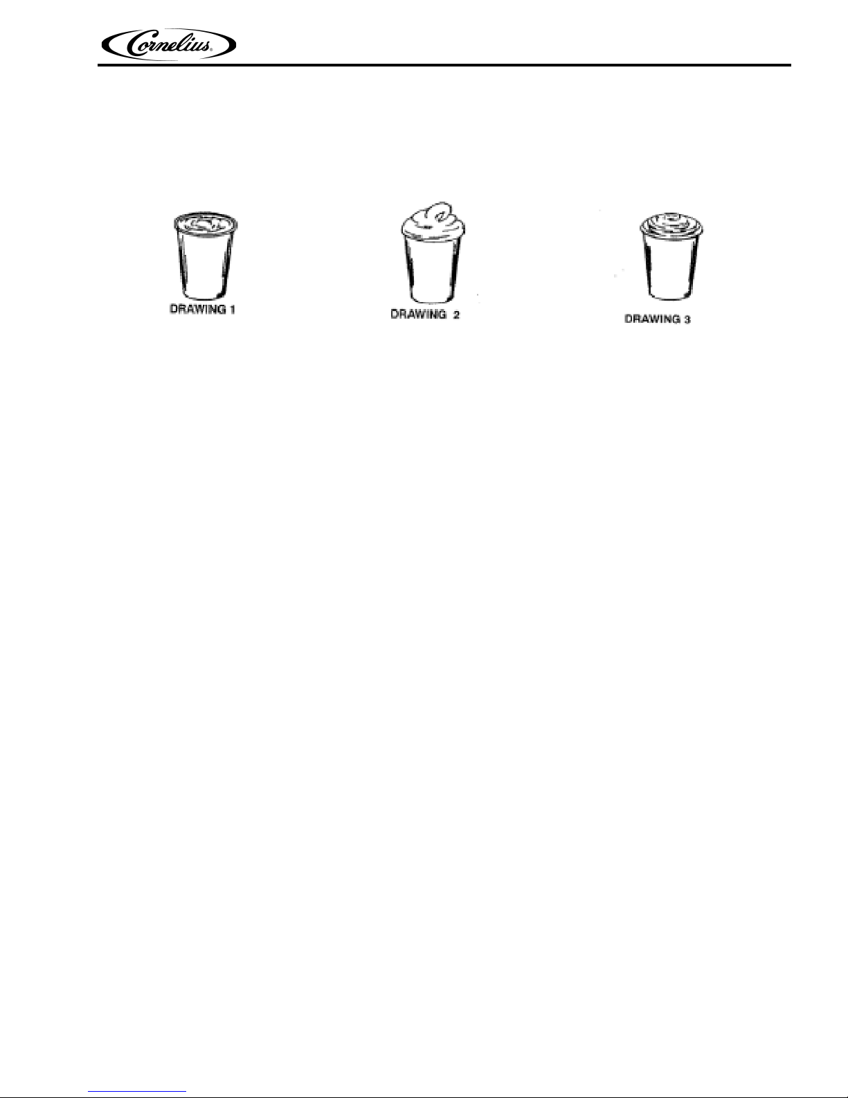
Figure 1.
Low Dispensing Volume Affects Overrun
When a unit sits idle for a period of time with no drinks being dispensed, CO2 gas in the system takes a “set”. When the first
few drinks are drawn off after an idle period, CO2 gas has less tendency to break out as the drink is dispensed. The result is
that these first drinks have less overrun than drinks dispensed during peak-use periods.
Carbonation Level in Liquid Product Affects Overrun
The higher the specific carbonation level in a given product, the greater the potential for carbonation breakout in frozen
carbonated form of that drink. For example, drinks with 3.0 volume of carbonation have more gas breakout in frozen
carbonated form and more overrun than drinks that contain 2.0 volumes of CO
2 gas.
Freezing Affects Overrun
Freezing causes approximately a 5-7 percent expansion in dispensed frozen carbonated drinks. The degree of
freezing is limited because the finished drink is intended to be sipped through a straw. This is not possible if the
product is too “solid”.
© 2008-2015, Cornelius Inc. - 5 - Publication Number: 621260373INS

Viper Installation Manual
INSTALLATION
DELIVERY, INSPECTION & UNPACKING
NOTE: Cornelius is not responsible for damaged freight. If damage is found, you must save all packaging
material and contact the freight carrier. Failure to contact the carrier within 48 hours of receipt
may void your claim.
1. Inspect the carton and note any damage, regardless if it appears minor. If the carton is damaged, note
on the consignee copy of the freight invoice “exterior carton damage – concealed damage possible” and
contact the freight company immediately.
2. Remove any staples along the bottom edge of the carton and lift the carton off the pallet.
3. Remove the exterior carton sleeve, internal fillers and plastic bag around the unit. Carefully inspect the
unit for damage.
4. Remove the bolts holding the dispenser to the pallet.
5. Remove the packing fillers from the top of the unit.
6. Inspect the dispenser cabinet and make sure it has no scratches, dents or any other cosmetic defects.
7. Make sure that the glass or plastic merchandiser panels are not scratched or cracked.
8. Open the packages of loose parts and inspect all of the parts for damage or missing parts. Check the
parts received against the packing list to insure receipt of all parts.
NOTE: If unit is installed more than three months from date of production, replace the seals according to
the instructions accompanying the spare seals supplied with the unit. Unite date of manufacture
is included in the unit serial no. as follows: The date code follows the first letter of the serial
number. The next four numbers reflect the date of manufacture. The first two represent the year,
the next two the week. For example, 62A0815xxxxxx would be a unit produced during the 15th
week of 2008.
COUNTER LOCATION
Select a location in a well ventilated area, close to a grounded electrical outlet and backroom connections. The counter must
be capable of supporting a minimum of 400 pounds. If possible do not place the unit close to hot and/or steaming machines.
The minimum clearance is: 2 in. (5.08 am) in back and 12 in. (30.48 am) on top of the unit. If both sides have a minimum
clearance of 2” (5.08 am), then the unit may be flush to the wall in the back.
This appliance is not intended for use by persons (including children) with reduced physical, sensory or mental capabilities, or
lack of experience and knowledge, unless they have been given supervision or instruction concerning use of the appliance by
a person responsible for their safety.
Children should be supervised to ensure that they do not play with the unit.
NOTE: Condenser air is drawn in from the sides or back and discharged out the top. Failure to maintain
clearance space will reduce the capacity of the unit and cause premature compressor failure.
INSTALLING LEG
NOTE: : Before installing legs, the plastic plugs must be removed.
Unpack the four (4) legs and install them into the threaded holes provided in the bottom of the unit. The installer must provide
flexibility in the product and utility supply lines to permit shifting the position of the dispenser sufficiently to clean the area
beneath it.
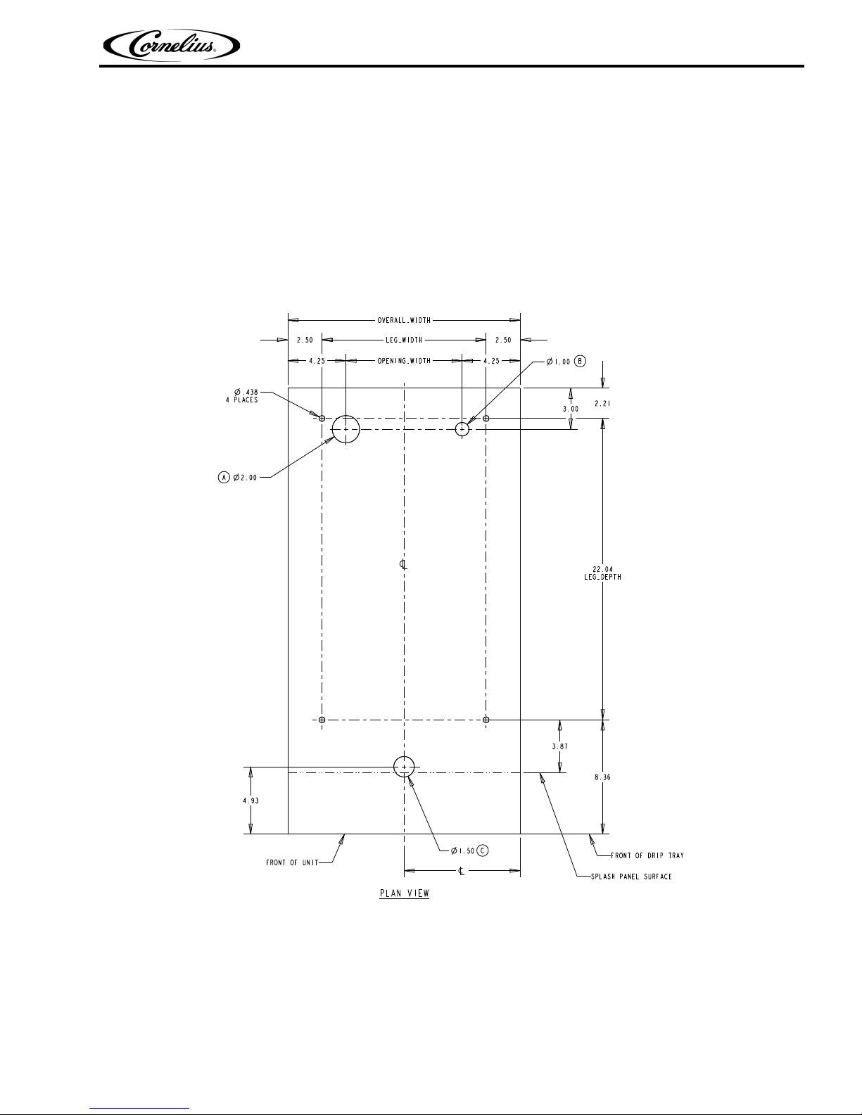
COUNTER MOUNTING
The Viper unit must be sealed to the counter. The MOUNTING TEMPLATE (Figure 2) indicates where openings can be cut in
the counter. Locate the desired position for the dispenser, then mark the outline dimensions on the counter using the
MOUNTING TEMPLATE. Cut openings in the counter.
Publication Number: 621260373INS - 6 - © 2008-2015, Cornelius Inc.
Viper Installation Manual
LEG_WIDTH
LEG_DEPTH
22.04
8.36
FRONT OF DRIP TRAY
3.87
SPLASH PANEL SURFACE
2.00
1.00
1.50
4 PLACES
.438
4.93
2.21
OVERALL_WIDTH
4.25OPENING_WIDTH4.25
3.00
2.50 2.50
PLAN VIEW
A
B
C
FRONT OF UNIT
Apply a continuous bead of National Sanitation Foundation (NSF) listed silastic sealant (Dow 732 or equal) approximately 1/4”
inside of the unit outline dimensions and around all openings. Then, position the unit on the counter within the outline
dimensions. All excess sealant must be wiped away immediately.
The beverage tubes, drain tube and power cord are routed through the large opening in the bottom of the unit. See
th
e MOUNTING TEMPLATE (see Figure 2), for locating the re
quired clearance hole in the counter for these utility
lines.
COUNTERTOP TEMPLATE INSTALLATION INSTRUCTIONS
Use the template shown in Figure 2 and the dimensions shown in Table 1: to drill the necessary holes for
installing the unit.
Figure 2
A - Opening for Product Tubes
B - Opening for Electrical Cables
C - Opening for Drip Tray Drain
© 2008-2015, Cornelius Inc. - 7 - Publication Number: 621260373INS
Viper Installation Manual
Power Cord
Syrup, Water and CO2
Input Lines
Table 1:
Model Overall Width (In.) Leg Width (In.) Opening Width (In.) Center Line (In.)
2FL 17.00 12.00 10.25 8.50
3FL 22.90 17.90 14.40 11.45
4FL 29.00 24.00 22.25 14.50
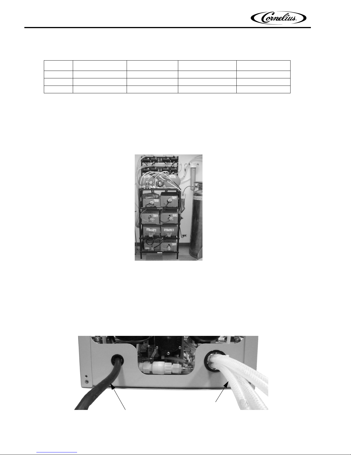
BACKROOM REQUIREMENTS
Typically the supplies for the unit are located in a backroom adjoining the service area. Syrup, water and CO2 lines are then
run from the backroom to the service area. The backroom supplies (syrup boxes, CO2, water filters and pumps) are typically
installed on a rack system that sits on the floor, as shown in Figure 3.The CO2 cylinder is normally mounted against the wall.
.
SUPPLY CONNECTIONS
All of the electrical and supply connections to the unit are typically located near the bottom rear of the unit. There are alternate
locations for the electrical and supply connections on the bottom of the unit, below the rear locations. The bottom connection
locations may be used if the unit is located directly against a wall.
The electrical connection is located at the
shown in Figure 4.
Publication Number: 621260373INS - 8 - © 2008-2015, Cornelius Inc.
Figure 3
left side of the rear panel and the tubing supplies are located on the right side, as
Figure 4.
Viper Installation Manual
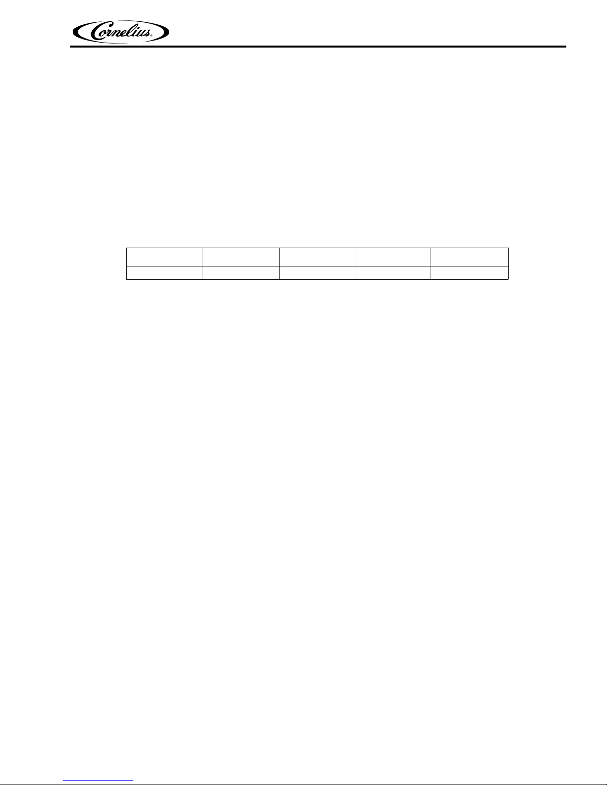
Electrical Requirements
Refer to the nameplate to determine the power requirements before connecting electrical power to the unit. All of the power
cords shall comply with safety requirements outlined in the EC Standards (EN60335-1 1 Clause 24.1) in countries where CE
compliance is required. All cords must be HD 21 or HD 22.
Line Voltage
The recommended line voltage range for the Viper unit is 215 to 245VAC. Measure the voltage at the wall outlet to verify
proper wiring of the outlet before plugging the Viper unit in.
Power
The power circuit must have some sort of overload protection, such as a circuit breaker or fuse that meets local and national
electrical codes.
Table 2 shows the power requirements for the various types of units.
Table 2.
2-Barrel 60Hz 3-Barrel 60Hz 4-Barrel 60Hz 2-Barrel 50Hz 3-Barrel 50Hz
20 A. Circuit 30 A. Circuit 30 A. Circuit 20 A. Circuit 30 A. Circuit
© 2008-2015, Cornelius Inc. - 9 - Publication Number: 621260373INS
 Loading...