

Page 1
Viper Motor Run Capacitor Kit Installation Instructions
!
WARNING:
!
WARNING:
!
WARNING:
CAUTION:
!
INSTALLATION INSTRUCTIONS
FIELD INSTALLATION INSTRUCTIONS FOR KIT 629097264, 629097286,
629097287, 629097265 & 629097285.
Before starting installation, read and understand all safety label and warnings on the machine. Also, review and
understand all safety instructions in the owners, installation and service manuals.
Failure to comply could result in serious injury, death or damage to the equipment.
Only trained and certified electrical, plumbing and refrigeration technicians should service this unit.
All wiring and plumbing must conform to national and local codes. Failure to comply could result in
serious injury, death or equipment damage.
Disconnect power to the unit before servicing. Follow all lock out/tag out procedures established by the user. Verify all
power is off to the unit before performing any work.
Failure to comply could result in serious injury, death or damage to the equipment.
Always be sure to keep the area around the unit clean and free of clutter.
Failure to keep this area clean may result in injury or equipment damage.
Table 1. Applicable Kit's
Item No. Part No. Description
1 629097264 Kit Motor Run Capacitor. Viper 2fl 60hz
2 629097286 Kit Motor Run Capacitor. Viper 3fl 60hz
3 629097287 Kit Motor Run Capacitor. Viper 4fl 60hz
4 629097265 Kit Motor Run Capacitor. Viper 2fl 50hz
5 629097285 Kit Motor Run Capacitor. Viper 3fl 50hz
629097264 Kit Includes:
Table 2. Parts Lists For Kit - 629097264
Item No. Part No. Description Quantity
1 342663000 Screw Tc 08-32 Paph 12 Stzi 23 1
2 620057820 Capacitor Motor Run Viper 60hz 2
3 620057846 Brkt Capacitor Hold-down Motor 1
4 620058302 Brkt Assembly Capacitor Viper 1
5 620720833 Screw Se 08-32 Paph 16 Stzi 4
Release Date: February 18, 2016 www.cornelius.com Revision: A
© 2016, Cornelius Inc. - 1 - Publication Number: 629097264INS
Page 2
Viper Motor Run Capacitor Kit Installation Instructions
629097286 Kit Includes:
Table 3. Parts Lists For Kit - 629097286
Item No. Part No. Description Quantity
1 342663000 Screw Tc 08-32 Paph 12 Stzi 23 2
2 620057820 Capacitor Motor Run Viper 60hz 3
3 620057846 Brkt Capacitor Hold-down Motor 2
4 620058302 Brkt Assembly Capacitor Viper 2
5 620720833 Screw Se 08-32 Paph 16 Stzi 8
629097287
629097265
Kit Includes:
Table 4. Parts Lists For Kit - 629097287
Item No. Part No. Description Quantity
1 342663000 Screw Tc 08-32 Paph 12 Stzi 23 2
2 620057820 Capacitor Motor Run Viper 60hz 4
3 620057846 Brkt Capacitor Hold-down Motor 2
4 620058302 Brkt Assembly Capacitor Viper 2
5 620720833 Screw Se 08-32 Paph 16 Stzi 8
Kit Includes:
Table 5. Parts Lists For Kit - 629097265
Item No. Part No. Description Quantity
1 342663000 Screw Tc 08-32 Paph 12 Stzi 23 1
2 620057821 Capacitor Motor Run Viper 50hz 2
3 620057846 Brkt Capacitor Hold-down Motor 1
4 620058302 Brkt Assembly Capacitor Viper 1
5 620720833 Screw Se 08-32 Paph 16 Stzi 4
629097285
Publication Number: 629097264INS - 2 - © 2016, Cornelius Inc.
Kit Includes:
Table 6. Parts Lists For Kit - 629097285
Item No. Part No. Description Quantity
1 342663000 Screw Tc 08-32 Paph 12 Stzi 23 2
2 620057821 Capacitor Motor Run Viper 50hz 3
3 620057846 Brkt Capacitor Hold-down Motor 2
4 620058302 Brkt Assembly Capacitor Viper 2
5 620720833 Screw Se 08-32 Paph 16 Stzi 8
Page 3
Viper Motor Run Capacitor Kit Installation Instructions
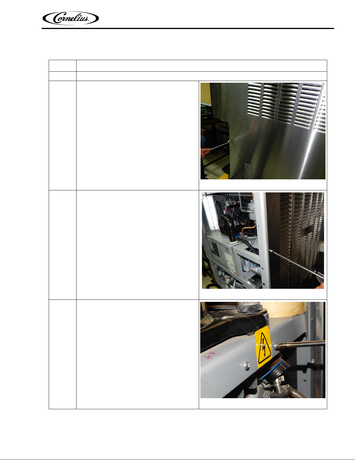
The instructions in Table 7 should be used for installation of the capacitor kit on Viper units.
Table 7. Installation Procedure
Step Action
1
Disconnect the power cord.
Remove 3 mounting screws from side panel.
2
Figure 1.
3 Remove 4 mounting screws from Back panel.
Figure 2.
Locate and remove the Bracket screws.
4
4 screws, 2bracket for 3 and 4 flavor unit.
2 screws,1bracket for 2flavor unit.
Figure 3.
© 2016, Cornelius Inc. - 3 - Publication Number: 629097264INS
Page 4

Viper Motor Run Capacitor Kit Installation Instructions
Table 7. Installation Procedure
Step Action
Gently remove the bracket and capacitor from the
5
frame.
Figure 4.
Carefully remove the connection wires from the
6
capacitor leads (2 for each capacitor).
Figure 5.
Turn the capacitor bracket over and unscrew the
7
ground wire(s) as seen.
Figure 6.
Publication Number: 629097264INS - 4 - © 2016, Cornelius Inc.
Page 5

Table 7. Installation Procedure
Step Action
Replace the old capacitor and bracket with new
capacitor and bracket.
The bracket will have two parts that fit together.
8
Use only the correct capacitor for your location.
1. 620057820 / 4UF 60HZ
2. 620047821 / 5UF 50HZ
Viper Motor Run Capacitor Kit Installation Instructions
Figure 7.
10
Slide the capacitor in two oval holes from the out-
9
side of the bracket as shown.
Slide the bracket holding the capacitor into second bracket and line up the lip and the screw
holes.
Figure 8.
Figure 9.
© 2016, Cornelius Inc. - 5 - Publication Number: 629097264INS
Page 6

Viper Motor Run Capacitor Kit Installation Instructions
Table 7. Installation Procedure
Step Action
11
12
Verify that the bracket covers the lip of the capaci-
tor and the screw holes line up on the side.
Figure 10.
Screw the bracket together using screw
#620720833 in the locations shown.
Figure 11.
13 Plug the wires back into the capacitor(s).
Figure 12.
Publication Number: 629097264INS - 6 - © 2016, Cornelius Inc.
Page 7

Table 7. Installation Procedure
Step Action
Align the bracket side with two holes with the
frame and screw the bracket in.
14
Use screw #620720833 in the locations shown.
Viper Motor Run Capacitor Kit Installation Instructions
15
16
Screw the ground wire into the bracket at this
location.
Use self taping screw #342663000.
Reattach the back panel and side panel with the screws.
Plug the unit and start as usual.
Mounting location
Figure 13.
Figure 14.
© 2016, Cornelius Inc. - 7 - Publication Number: 629097264INS
 Loading...