

Page 1
®
FCB PINNACLE
2 and 4 Flavor
Service Manual
FCB - 2 Flavor FCB - 4 Flavor
Release Date: October 30, 2003
Publication Number: 560007298SER
Revision Date: May 07, 2014
Revision: J
Page 2

CONTACT INFORMATION
The products, technical information, and instructions contained in this manual are subject to change without notice. These instructions are not intended to cover all details or variations of the equipment, nor to
provide for every possible contingency in the installation, operation or maintenance of this equipment.
This manual assumes that the person(s) working on the equipment have been trained and are skilled in
working with electrical, plumbing, pneumatic, and mechanical equipment. Appropriate safety precautions
should be followed and all local safety and construction requirements should be met.
To inquire about current revisions of this and other documentation, or for assistance with any Cornelius
product contact:
www.cornelius.com
800-238-3600
This document contains proprietary information and it may not be reproduced in any way without permission from Cornelius.
Printed in U.S.A.
Copyright © 2003-2014, All Rights Reserved, Cornelius Inc.
Page 3

TABLE OF CONTENTS
Safety . . . . . . . . . . . . . . . . . . . . . . . . . . . . . . . . . . . . . . . . . . . . . . . . . . . . . . . . . . . . . . . 1
Safety Instructions . . . . . . . . . . . . . . . . . . . . . . . . . . . . . . . . . . . . . . . . . . . . . . . . . . . 1
Read and Follow all Safety Instructions . . . . . . . . . . . . . . . . . . . . . . . . . . . . . . . .1
Recognize Safety Alerts . . . . . . . . . . . . . . . . . . . . . . . . . . . . . . . . . . . . . . . . . . . .1
Different Types of Alerts . . . . . . . . . . . . . . . . . . . . . . . . . . . . . . . . . . . . . . . . . . . .1
Safety Tips . . . . . . . . . . . . . . . . . . . . . . . . . . . . . . . . . . . . . . . . . . . . . . . . . . . . . . . . . 1
Qualified Service Personnel. . . . . . . . . . . . . . . . . . . . . . . . . . . . . . . . . . . . . . . . . . . . 1
CO2 (Carbon Dioxide) Warning . . . . . . . . . . . . . . . . . . . . . . . . . . . . . . . . . . . . . . . . . 1
Shipping And Storage . . . . . . . . . . . . . . . . . . . . . . . . . . . . . . . . . . . . . . . . . . . . . . . . 2
Magnet Warning. . . . . . . . . . . . . . . . . . . . . . . . . . . . . . . . . . . . . . . . . . . . . . . . . . . . . 2
System Overview . . . . . . . . . . . . . . . . . . . . . . . . . . . . . . . . . . . . . . . . . . . . . . . . . . . . . . 3
Product Overview. . . . . . . . . . . . . . . . . . . . . . . . . . . . . . . . . . . . . . . . . . . . . . . . . . . . 3
Specifications. . . . . . . . . . . . . . . . . . . . . . . . . . . . . . . . . . . . . . . . . . . . . . . . . . . . . . . 4
Dimensions . . . . . . . . . . . . . . . . . . . . . . . . . . . . . . . . . . . . . . . . . . . . . . . . . . . . . .4
Line Voltage . . . . . . . . . . . . . . . . . . . . . . . . . . . . . . . . . . . . . . . . . . . . . . . . . . . . .4
Accessories — Included . . . . . . . . . . . . . . . . . . . . . . . . . . . . . . . . . . . . . . . . . . . .4
Accessories — Optional . . . . . . . . . . . . . . . . . . . . . . . . . . . . . . . . . . . . . . . . . . . .5
Operation and Service. . . . . . . . . . . . . . . . . . . . . . . . . . . . . . . . . . . . . . . . . . . . . . . . . . 6
Maintaining Product Quality
Cornelius FCB Equipment - Operator Instructions. . . . . . . . . . . . . . . . . . . . . . . . . . . 6
1. Dispensed Product Throughput . . . . . . . . . . . . . . . . . . . . . . . . . . . . . . . . . . . .6
2. Programmed Defrost Scheduling . . . . . . . . . . . . . . . . . . . . . . . . . . . . . . . . . . .6
3. Sleep Mode Recommendations . . . . . . . . . . . . . . . . . . . . . . . . . . . . . . . . . . . .7
4. Viscosity Setting . . . . . . . . . . . . . . . . . . . . . . . . . . . . . . . . . . . . . . . . . . . . . . . .7
Service . . . . . . . . . . . . . . . . . . . . . . . . . . . . . . . . . . . . . . . . . . . . . . . . . . . . . . . . . . . . . . 8
Preventive Maintenance . . . . . . . . . . . . . . . . . . . . . . . . . . . . . . . . . . . . . . . . . . . . . . 8
Preventive Maintenance Summary . . . . . . . . . . . . . . . . . . . . . . . . . . . . . . . . . . . .8
Cleaning Air Filter (Integral Only) . . . . . . . . . . . . . . . . . . . . . . . . . . . . . . . . . . . . .8
Sanitizing . . . . . . . . . . . . . . . . . . . . . . . . . . . . . . . . . . . . . . . . . . . . . . . . . . . . . . . .8
Stainless Steel Double Check Valve Inspection & Cleaning . . . . . . . . . . . . . . . .11
Check BRIX . . . . . . . . . . . . . . . . . . . . . . . . . . . . . . . . . . . . . . . . . . . . . . . . . . . . .11
Adjustments . . . . . . . . . . . . . . . . . . . . . . . . . . . . . . . . . . . . . . . . . . . . . . . . . . . . . . . 12
Water, Syrup, & CO2 Regulator Settings . . . . . . . . . . . . . . . . . . . . . . . . . . . . . .12
Pinnacle Control System . . . . . . . . . . . . . . . . . . . . . . . . . . . . . . . . . . . . . . . . . . . . . 12
Control System Overview . . . . . . . . . . . . . . . . . . . . . . . . . . . . . . . . . . . . . . . . . .12
Control Panel Menu Descriptions . . . . . . . . . . . . . . . . . . . . . . . . . . . . . . . . . . . .15
Control Panel Error Descriptions . . . . . . . . . . . . . . . . . . . . . . . . . . . . . . . . . . . . .36
Component Service . . . . . . . . . . . . . . . . . . . . . . . . . . . . . . . . . . . . . . . . . . . . . . . . . . . 38
Magnet Assembly Replacement . . . . . . . . . . . . . . . . . . . . . . . . . . . . . . . . . . . . . . . 38
DC Control Drive Motor Board Replacement - Emerson . . . . . . . . . . . . . . . . . . . . . 40
Main and Product Delivery Board Replacement - Emerson . . . . . . . . . . . . . . . . . . 40
Chip Change Procedure . . . . . . . . . . . . . . . . . . . . . . . . . . . . . . . . . . . . . . . . . . . . . 41
DC Inverter Board Replacement - Baldor . . . . . . . . . . . . . . . . . . . . . . . . . . . . . . . . 42
Main and Product Delivery Board Replacement - Baldor . . . . . . . . . . . . . . . . . . . . 42
Display Board Replacement . . . . . . . . . . . . . . . . . . . . . . . . . . . . . . . . . . . . . . . . . . 43
Merchandiser Light Ballast Replacement . . . . . . . . . . . . . . . . . . . . . . . . . . . . . . . . 43
Page 4

Transformer Replacement . . . . . . . . . . . . . . . . . . . . . . . . . . . . . . . . . . . . . . . . . . . . 44
Contactor Replacement . . . . . . . . . . . . . . . . . . . . . . . . . . . . . . . . . . . . . . . . . . . . . . 44
Start Components Replacement . . . . . . . . . . . . . . . . . . . . . . . . . . . . . . . . . . . . . . . 44
Pump Motor Replacement . . . . . . . . . . . . . . . . . . . . . . . . . . . . . . . . . . . . . . . . . . . . 45
Agitator Motor Replacement . . . . . . . . . . . . . . . . . . . . . . . . . . . . . . . . . . . . . . . . . . 45
Syrup/Water Valve Replacement. . . . . . . . . . . . . . . . . . . . . . . . . . . . . . . . . . . . . . . 45
CO2 Regulator Replacement. . . . . . . . . . . . . . . . . . . . . . . . . . . . . . . . . . . . . . . . . . 46
Blendonator Float Switch Replacement. . . . . . . . . . . . . . . . . . . . . . . . . . . . . . . . . . 46
Blendonator Tank Replacement: . . . . . . . . . . . . . . . . . . . . . . . . . . . . . . . . . . . . . . . 46
Hy-Pot Test Procedure . . . . . . . . . . . . . . . . . . . . . . . . . . . . . . . . . . . . . . . . . . . . . . 47
Hall Effect Sensor Diagnosis & Replacement - Baldor . . . . . . . . . . . . . . . . . . . . . . 48
Hall Board Diagnostic Procedure: . . . . . . . . . . . . . . . . . . . . . . . . . . . . . . . . . . . .48
DC Stator Test - Emerson . . . . . . . . . . . . . . . . . . . . . . . . . . . . . . . . . . . . . . . . . . . . 49
DC Stator Test - Baldor . . . . . . . . . . . . . . . . . . . . . . . . . . . . . . . . . . . . . . . . . . . . . . 50
DC Stator Assembly Replacement . . . . . . . . . . . . . . . . . . . . . . . . . . . . . . . . . . . . . 51
DC Stator Assembly Replacement - Baldor. . . . . . . . . . . . . . . . . . . . . . . . . . . . . . . 52
Condenser Fan Motor Replacement (Integral Only) . . . . . . . . . . . . . . . . . . . . . . . . 53
Condenser Filter Replacement (Integral Only) . . . . . . . . . . . . . . . . . . . . . . . . . . . . 53
Foam Pack Replacement: . . . . . . . . . . . . . . . . . . . . . . . . . . . . . . . . . . . . . . . . . . . . 54
Compressor Replacement: . . . . . . . . . . . . . . . . . . . . . . . . . . . . . . . . . . . . . . . . . . . 55
Hot Gas Valve Rebuilding:. . . . . . . . . . . . . . . . . . . . . . . . . . . . . . . . . . . . . . . . . . . . 55
Pulse Valve Replacement:. . . . . . . . . . . . . . . . . . . . . . . . . . . . . . . . . . . . . . . . . . . . 56
Water Pressure Regulator / Switch Replacement:. . . . . . . . . . . . . . . . . . . . . . . . . . 56
Water Strainer Cleaning: . . . . . . . . . . . . . . . . . . . . . . . . . . . . . . . . . . . . . . . . . . . . . 56
Merchandiser Lamp Removal and Installation. . . . . . . . . . . . . . . . . . . . . . . . . . . . . 57
Removal . . . . . . . . . . . . . . . . . . . . . . . . . . . . . . . . . . . . . . . . . . . . . . . . . . . . . . .57
Installation . . . . . . . . . . . . . . . . . . . . . . . . . . . . . . . . . . . . . . . . . . . . . . . . . . . . . .58
Troubleshooting. . . . . . . . . . . . . . . . . . . . . . . . . . . . . . . . . . . . . . . . . . . . . . . . . . . . . . 60
Troubleshooting the System . . . . . . . . . . . . . . . . . . . . . . . . . . . . . . . . . . . . . . . . . . 60
Troubleshooting Product Not Cold. . . . . . . . . . . . . . . . . . . . . . . . . . . . . . . . . . . . . . 61
Appendix A - Historic Brix Procedures . . . . . . . . . . . . . . . . . . . . . . . . . . . . . . . . . . . 63
Section 1: 3-Way Valve Brixing Procedure . . . . . . . . . . . . . . . . . . . . . . . . . . . . . . . 63
Section 2: Shut-Off Valve and Blendonator Outlet Brix Sample Tube Procedure . . 66
Appendix B . . . . . . . . . . . . . . . . . . . . . . . . . . . . . . . . . . . . . . . . . . . . . . . . . . . . . . . . . . 67
Valve Torque and Staking . . . . . . . . . . . . . . . . . . . . . . . . . . . . . . . . . . . . . . . . . . . . 67
Delta Valve . . . . . . . . . . . . . . . . . . . . . . . . . . . . . . . . . . . . . . . . . . . . . . . . . . . . .68
Motorman Valve . . . . . . . . . . . . . . . . . . . . . . . . . . . . . . . . . . . . . . . . . . . . . . . . .70
Page 5
SAFETY
SAFETY INSTRUCTIONS
Read and Follow all Safety Instructions
Read and follow all safety instructions in this manual and on the machine (decals, labels, and laminated
cards).
Read and understand all applicable OSHA (Occupation Safety and Health Administration) safety regula-
tions before operating the machine.
Recognize Safety Alerts
This is the safety alert symbol. When you see it in this manual or on the machine be
alert to the potential of personal injury or damage to the machine.
Different Types of Alerts
There are 3 types of safety alerts:
DANGER — Indicates an immediate hazardous situation which if not avoided WILL result in seri-
ous injury, death, or equipment damage.
Pinnacle 2 and 4 Flavor Service Manual
WARNING — Indicates a potentially hazardous situation which, if not avoided, COULD result in
serious injury, death, or equipment damage.
CAUTION — Indicates a potentially hazardous situation which, if not avoided, MAY result in
minor or moderate injury or equipment damage.
SAFETY TIPS
• Carefully read all safety messages in this manual and safety signs on the machine.
• Keep safety signs in good condition and replace missing or damaged safety signs.
• Learn how to operate the machine and how to use the controls properly.
• Do not let anyone operate the machine without proper training. This appliance is not intended for use
by very young children or infirm persons without supervision. Young children should be supervised to
ensure that they do not play with the appliance.
• Keep your machine in proper working condition and do not allow unauthorized modifications to the
machine.
QUALIFIED SERVICE PERSONNEL
CAUTION — Only trained and certified electrical, plumbing and refrigeration technicians should
service this unit. ALL WIRING AND PLUMBING MUST CONFORM TO NATIONAL AND LOCAL
CODES.
CO2 (CARBON DIOXIDE) WARNING
WARNING
CO
gas leaks in the entire CO2 and soft drink system. If a CO2 gas leak is suspected, particularly
2
in a small area, immediately ventilate the contaminated area before attempting to repair the leak.
Personnel exposed to high concentration of CO
rapidly by loss of consciousness.
© 2003-2014, Cornelius Inc.. - 1 - Publication Number: 560007298SER
— CO2 Displaces Oxygen. Strict Attention must be observed in the prevention of
gas will experience tremors which are followed
2
Page 6
SHIPPING AND STORAGE
CAUTION — Before shipping, storing, or relocating the Unit, syrup systems must be sanitized
and all sanitizing solution must be purged from the syrup systems. All liquids, after sanitizing, must
be purged from the unit. A freezing ambient environment will cause residual sanitizing solution or
water remaining inside the Unit to freeze resulting in damage to the internal components.
MAGNET WARNING
CAUTION — After removing the very strong magnet from the freeze cylinder, be careful to avoid
crushing fingers between the magnet and any ferrous metal. Keep the magnet free from metallic
debris and wipe clean prior to reinstallation.
WARNING — Strong Magnetic Field.
Person wearing pacemaker, implanted cardioverter defibrillator, or other implanted medical device
may be affected by the magnetic field and must keep the magnet at 6 or more inches from the
device. The magnetic field can affect operation of these devices which may cause bodily injury or
death.
If disruption of device occurs or operation is adversely effected, immediately move the victim far
away from magnet and seek medical assistance.
Pinnacle 2 and 4 Flavor Service Manual
© 2003-2014, Cornelius Inc. - 2 - Publication Number: 560007298SER
Page 7
PRODUCT OVERVIEW
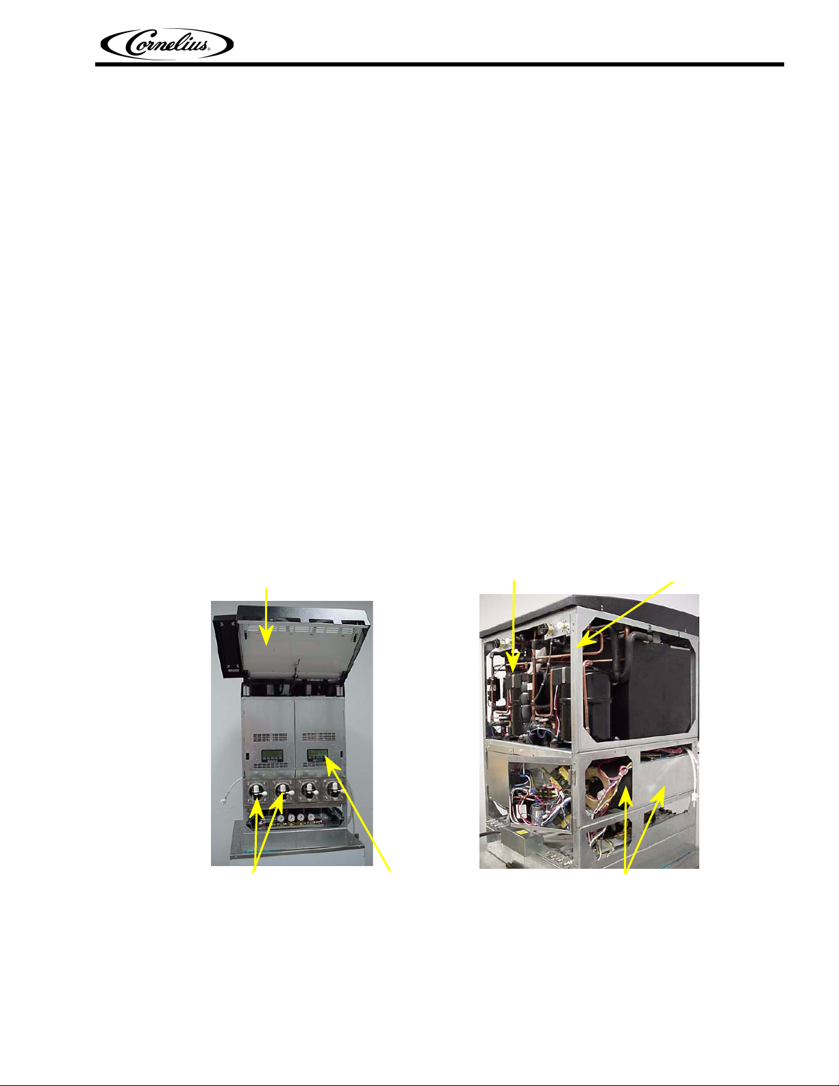
The 2 and 4 Flavor Pinnacle (see pictures below) consists of the following:
• 2 or 4 freeze cylinders each containing an internal beater bar driven by DC electric motors, utilizing
external stator coils and internal rotor magnets. These motors contain no seals there by eliminating leak-
age and minimizing preventive maintenance.
• A DC motor using magnetics to drive the beater bars in each cylinder.
• 1 refrigeration systems per 2 barrels, 1 blendonator assembly per barrel, a programmable defrost sys-
tem to defrost the freeze cylinders, and interconnecting tubing, components and fittings necessary to reg-
ulate, transfer, and dispense a quality frozen carbonated product.
• The components are enclosed in a steel frame. The frame is then covered with panels.
• The panels enclosing the components and frame are easily removable to facilitate installation, service,
and maintenance.
• Each barrel has a transparent faceplate, with an integral relief valve and a removable self-closing dis-
pensing valve mounted on the front of each faceplate.
• A removable drip tray, with cup rest is located directly below the dispensing valves.
Pinnacle 2 and 4 Flavor Service Manual
SYSTEM OVERVIEW
• Lighted merchandising compliments each unit.
• 2 or 4 blendonators using a refrigerated ice coil and water bath to cool the product before carbonating.
• 1 self contained refrigeration system for the 2 flavor and 2 for the 4 flavor.
• A programmable system to defrost the freeze cylinders, and components that dispense the product.
• Control Panel with 5 buttons that control operational and diagnostic functions and settings.
Lighted Display Panel
Double Refrigeration System
Steel Frame
Dispensing Valves & Face Plates Control Panel
FIGURE 1 FIGURE 2
© 2003-2014, Cornelius Inc. - 3 - Publication Number: 560007298SER
Foam Pack& Motor
Page 8
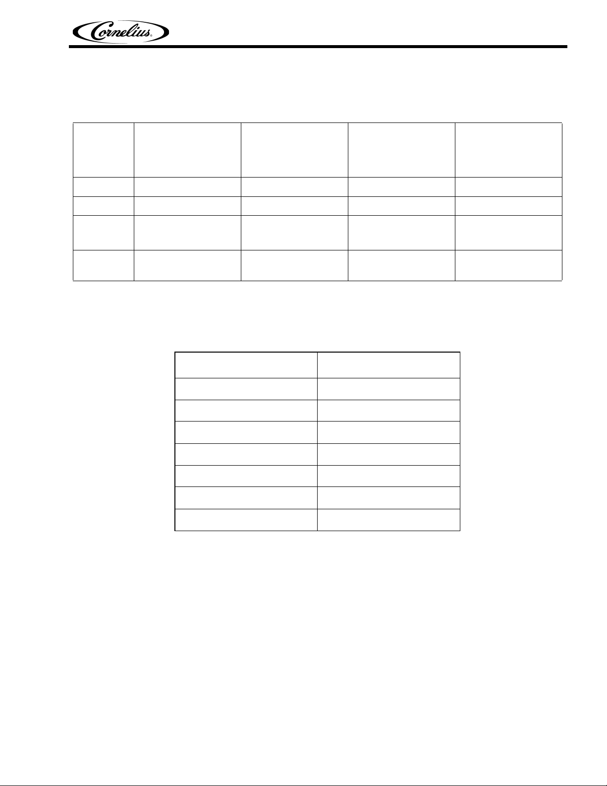
SPECIFICATIONS
Dimensions
Pinnacle 2 and 4 Flavor Service Manual
Height
Width
Depth
Shipping
weight
Line Voltage
The recommended line voltages for the Pinnacle unit are as follows:
The unit has a low voltage cut out at 180 VAC and a high voltage cut out at 260 VAC.
Overcounter
Integral/Remote 2
Flavor
43.75 in. 43.75 in. 74.75 in. 74.75 in.
14.5 in. 28 in. 14.5 in. 28 in.
31 in.
36 in. (with drip
tray)
429 lbs. (approx.) 732 lbs. (approx.) 525 lbs. (approx.) 858 lbs. (approx.)
Voltage Corrective Action
Below 180 V Do not connect unit.
180 to 190 VAC Boost voltage by +32 V.
Overcounter
Integral/Remote 4
Flavor
31 in.
36 in. (with drip
tray)
Overcounter
Integral/Remote 2
Flavor w/ Cornelius
Cart
32 in.
37 in. (with drip
tray)
Overcounter
Integral/Remote 4
Flavor w/ Cornelius
Cart
32 in.
37 in. (with drip
tray)
191 to 207 VAC Boost voltage by +16 V.
208 to 240 VAC Use line voltage.
241 to 253 VAC Reduce voltage by -16 V.
254 to 272 VAC Reduce voltage by -32 V.
Above 272 VAC Do not connect unit.
Accessories — Included
Magnet puller . . . . . . . . . . . . . . . . . . . . . . . . . . . . . . . . . . . . . . . . 560003662
John Guest fitting tool . . . . . . . . . . . . . . . . . . . . . . . . . . . . . . . . . . 560003481
Brush . . . . . . . . . . . . . . . . . . . . . . . . . . . . . . . . . . . . . . . . . . . . . . 325216000
© 2003-2014, Cornelius Inc. - 4 - Publication Number: 560007298SER
Page 9

Accessories — Optional
Installation kit . . . . . . . . . . . . . . . . . . . . . . . . . . . . . . . . . . . . . . . . 1155
Cup holder . . . . . . . . . . . . . . . . . . . . . . . . . . . . . . . . . . . . . . . . . . 511006000
Cornelius refractometer, 0-30 scale . . . . . . . . . . . . . . . . . . . . . . . 511004000
Transformer. . . . . . . . . . . . . . . . . . . . . . . . . . . . . . . . . . . . . . . . . . 325674000
Remote Condensing Unit (one required for each two barrels) . . . 631700512
Refrigeration line sets (one required for each two barrels) . . . . . 561441250
Refrigeration line sets with flexible end and 90 degree fittings
(one required for each two barrels). . . . . . . . . . . . . . . . . . . . . . . . 561441253
Cornelius cart, stainless steel, 2 Flavor . . . . . . . . . . . . . . . . . . . . 620201705
Cornelius cart, stainless steel, 4 Flavor . . . . . . . . . . . . . . . . . . . . 620201701
Leg 4” Height (4 required per unit) . . . . . . . . . . . . . . . . . . . . . . . . 3184
2 FL Generic main graphic and flavor card set . . . . . . . . . . . . . . . 560007299
4 FL Generic main graphic and flavor card set . . . . . . . . . . . . . . . 560007300
Pinnacle 2 and 4 Flavor Service Manual
© 2003-2014, Cornelius Inc. - 5 - Publication Number: 560007298SER
Page 10
Pinnacle 2 and 4 Flavor Service Manual
OPERATION AND SERVICE
MAINTAINING PRODUCT QUALITY
CORNELIUS FCB EQUIPMENT - OPERATOR INSTRUCTIONS
It has been determined that the following factors can affect the rate at which product quality diminishes
(as indicated by a change in product appearance).
1. Dispensed Product Throughput
2. Programmed Defrost Scheduling
3. Viscosity Setting
Cornelius recommends the following instructions be read and followed relative to operating and
establishing settings with the FCB equipment. Cornelius equipment service manuals contain instructions
on how to program settings within the control system. Operators who have not been trained on servicing
Cornelius FCB equipment should not attempt to modify equipment settings but should contact an
accredited service provider.
Cornelius makes the following recommendations to help assure maximum product quality:
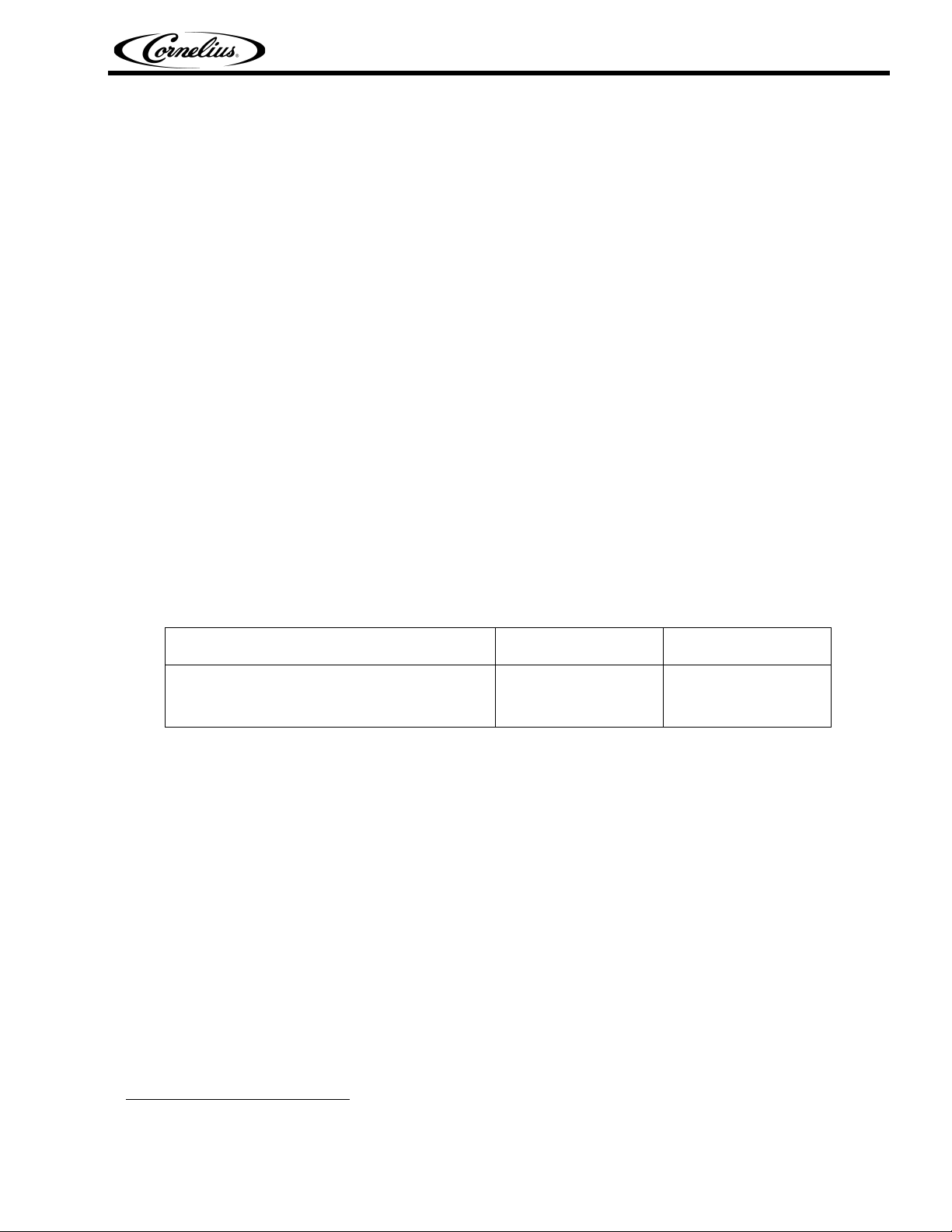
1. Dispensed Product Throughput
FCB equipment is designed to provide a high throughput of frozen carbonated dispensed product to meet
peak draw demands. Where low product throughput is experienced, there is the potential for product
quality to diminish. The matrix below outlines the minimum throughput per barrel that must be dispensed
on a 24 hour basis.
Dispensed product throughput matrix
Pinnacle Viscosity </= 4 Viscosity >4
Volume of dispensed product per barrel
per 24 hours required to maintain product
quality.
Cornelius recommends that, in conditions where the FCB machine is operational and the
minimum throughput (set forth in the matrix above) is not met on a per barrel basis, product
should be dispensed and discarded to increase throughput and help assure that product quality
is maintained.
2. Programmed Defrost Scheduling
The control system in Cornelius FCB equipment includes a function to automatically defrost product in
the barrel at programmed times. Programmed defrosts must be scheduled frequently to ensure that
product quality within the barrel is maintained. Failure to defrost regularly during periods of low
throughput will allow increased ice crystal growth, with a possible decrease in product quality and will
cause drive errors. Regular throughput of dispensed product will replenish the barrel frequently with liquid
and reduce the requirements of programmed defrosts.
Cornelius recommends that programmed defrosts be scheduled to occur during any 3 hour
window during which time dispensed product throughput is low. Low throughput is defined as
less than 8 x 16oz drinks per barrel during any 3-hour window.
1
48 oz 60 oz
1. Data in matrix assumes equipment has been correctly installed, commissioned and calibrated as per
directions contained in all technical literature published by Cornelius and the recommendations contained in this document have been followed.
© 2003-2014, Cornelius Inc. - 6 - Publication Number: 560007298SER
Page 11

3. Sleep Mode Recommendations
Cornelius recommends programming a sleep for any period of time, over 3 hours, in which the unit will
not have any usage. If the programmed sleep is longer than 6 hours, Cornelius also recommends turning
the ice bank off in the options menu. This will increase the life of the machine and reduce the energy con-
sumption.
A wake time must be programmed to return the unit to normal operation. Cornelius recommends pro-
gramming the wake 30 minutes before the unit is needed if the ice bank option is set to ON and 60 min-
utes before the unit is needed if the ice bank option is set to OFF. These are the time recommended if the
ambient temperature is at 75
ambient temperature require more time for the ice bank to build).
o
F. The times will vary depending on the ambient temperature (a higher
4. Viscosity Setting
The control system in Cornelius FCB equipment includes a function to select the desired product
viscosity. This function is referred to as “Viscosity Setting”. There is a selectable Viscosity range of 1–9
for the Pinnacle. The higher the number selected the more viscous the frozen product in the barrel will
become. This increased viscosity is achieved by freezing the product in the barrel to a lower temperature
thereby increasing ice crystal size/growth. As the ice crystal size increases, however, there is potential for
product quality to diminish.
Cornelius recommends that the viscosity settings be set at the lowest possible setting to achieve
the desired drink quality. In most typical installations using a sugar-based syrup, acceptable
drink quality can be achieved by programmed Viscosity Settings in the range of 3-5 for Pinnacle.
Pinnacle 2 and 4 Flavor Service Manual
Diet FCB syrups freeze much more readily than sugar based syrups, so the Viscosity Setting
should be selected at the minimum value available (which is 1 for the Pinnacle).
© 2003-2014, Cornelius Inc. - 7 - Publication Number: 560007298SER
Page 12
Pinnacle 2 and 4 Flavor Service Manual
SERVICE
CAUTION — Only trained and certified electrical, plumbing and refrigeration technicians should
service this unit. ALL WIRING AND PLUMBING MUST CONFORM TO NATIONAL AND LOCAL
CODES.
PREVENTIVE MAINTENANCE
Preventive Maintenance Summary
Preventive Maintenance Summary
Procedure Frequency
Clean air filter (on air cooled units) Monthly or as necessary
Clean condenser every 6 months
Sanitize unit every 6 months
Change or rotate scraper blades every 6 months
Inspect Double Liquid Check Valve every 6 months
Check for leaks every 6 months
Check BRIX every 6 months
Clean BIB connectors every 6 months
Check clock setting every 6 months
Cleaning Air Filter (Integral Only)
1. The air filter should be cleaned every month. Remove the filter by sliding it straight back. Wash with
mild soap solution, rinse with clean water, and shake out excess water (or blow with low pressure com-
pressed air if available).
2. Vacuum the condenser coil or blow it out with low pressure compressed air before reinstalling the air
filter.
3. Reinstall the air filter.
Sanitizing
The syrup systems should be sanitized every 6 months per the following procedure using a non-scented
liquid household bleach containing a 5.25% sodium hypochlorite concentration.
1. Press <OFF> from the BARREL STATUS menu on the Control Panels to stop beater and refrigeration
on all cylinders.
2. Take the following actions from the Control Panel:
• From the BARREL STATUS menu, press <MENU>.
• From the CHOOSE MODE menu, select <MANUAL DEFROST> and press <GO>.
• Select barrel and press <DFRST>.
© 2003-2014, Cornelius Inc. - 8 - Publication Number: 560007298SER
Page 13
Pinnacle 2 and 4 Flavor Service Manual
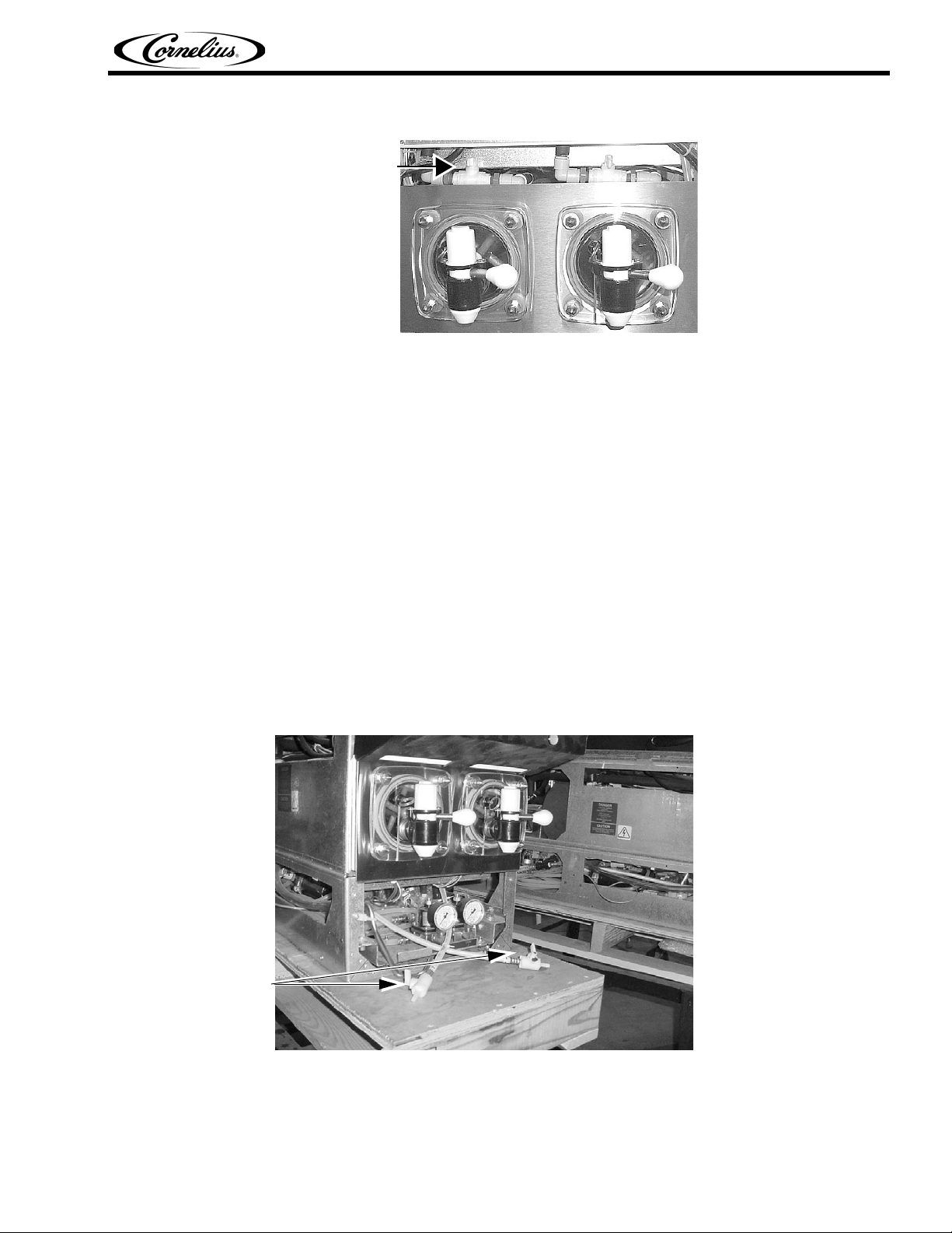
3. Close barrel # 1 freeze cylinder shutoff valve (see below).
Freeze
Cylinder
Shutoff Valve
FIGURE 3
4. Turn blendonator #1 OFF (from the BLENDONATOR menu) to prevent more product from entering the
blendonator.
5. Place container under barrel # 1 dispensing valve. Open the valve and dispense all product from the
freeze cylinder and the blendonator. As product level lowers in the freeze cylinder partially close the valve
to avoid spurting.
6. Disconnect bag-in-box from barrel # 1.
7. Wash the system by completing the following steps:
• Use a clean 5-gallon pail (bag-in-box system) filled with a solution of household liquid detergent
and warm water. Mix approximately 1 ounce of household liquid detergent per gallon of warm water.
• Connect the sanitizing fitting (p/n cc 28688) to the bag-in-box connector. Put the connector in the
bucket of wash water.
• Turn barrel # 1 blendonator ON (from BLENDONATOR menu) to fill blendonator.
• Fill barrel # 1 with washing solution by repeatedly pulling and releasing the faceplate relief valve
until solution comes out.
• Open the dispensing valve until solution flows from the valve, then close the valve.
• Open blendonator sample valve (see FIGURE 4) until solution flows from the valve, then close the
valve.
BRIX Sample
Valves
FIGURE 4
• Place barrel # 1 in MOTOR mode (from ON/OFF/MOTOR menu) to start barrel # 1 beater. Allow
beater to operate for 5–minutes, then place barrel # 1 in OFF mode (from ON/OFF/MOTOR menu) to
stop the beater.
© 2003-2014, Cornelius Inc. - 9 - Publication Number: 560007298SER
Page 14

Pinnacle 2 and 4 Flavor Service Manual
8. Flush the wash water from the system by completing the following steps:
• Turn barrel # 1 blendonator OFF (from BLENDONATOR menu) to prevent more wash water from
entering the blendonator.
• Place container under barrel # 1 dispensing valve. Open the dispense valve and dispense all wash
water from the freeze cylinder and the blendonator. As the wash water level lowers in the freeze cylinder partially close the valve to avoid spurting.
• Use a clean syrup tank (syrup tank system) or a clean 5-gallon pail (bag-in-box system) filled with
plain water.
• Connect the sanitizing fitting to the bag-in-box connector. Put the connector in the bucket of plain
water.
• Turn barrel # 1 blendonator ON (from BLENDONATOR menu) to fill blendonator.
• Fill barrel # 1 with plain water by repeatedly pulling and releasing the faceplate relief valve until
solution comes out.
• Open the dispensing valve until water flows from the valve, then close the valve.
• Open blendonator sample valve (see FIGURE 4) until water flows from the valve, then close the
valve.
• Place barrel # 1 in MOTOR mode (from ON/OFF/MOTOR menu) to start barrel # 1 beater. Allow
beater to operate for 2–minutes, then place barrel # 1 in OFF mode (from ON/OFF/MOTOR menu) to
stop the beater.
9. Sanitize the system by completing the following steps:
• Turn barrel # 1 blendonator OFF (from BLENDONATOR menu) to prevent more plain water from
entering the blendonator.
• Place container under barrel # 1 dispensing valve. Open the dispense valve and dispense all plain
water from the freeze cylinder and the blendonator. As the plain water level lowers in the freeze cylinder partially close the valve to avoid spurting.
• Use a clean 5-gallon pail (bag-in-box system) to prepare sanitizing solution. Mix approximately 1
ounce of household bleach per gallon of warm water. When the blendonator runs it mixes with potable water to give proper mixture.
• Put the sanitizing connector in the bucket of sanitizing solution.
NOTE: This mixture will provide 800-ppm of chlorine. Sanitizing solution will be diluted to approx-
imately 200-ppm inside the blendonator tank after carbonated water has been mixed with the san-
itizing solution.
NOTE: If powder sanitizer is used be sure it is thoroughly dissolved and mixed with the correct
amount of water.
• Turn barrel # 1 blendonator ON (from BLENDONATOR menu) to fill blendonator.
• Fill barrel # 1 with sanitizing solution by repeatedly pulling and releasing the faceplate relief valve
until solution comes out.
• Open the dispensing valve until solution flows from the valve, then close the valve.
• Open blendonator sample valve (see FIGURE 4) until solution flows from the valve, then close the
valve.
• Place barrel # 1 in MOTOR mode (from ON/OFF/MOTOR menu) to start barrel # 1 beater. Allow
beater to operate for at least 10 minutes but not more than 15 minutes. Then place barrel # 1 in OFF
mode (from ON/OFF/MOTOR menu) to stop the beater.
• Turn barrel # 1 blendonator OFF (from BLENDONATOR menu) to prevent more sanitizing solution
from entering the blender tank.
© 2003-2014, Cornelius Inc. - 10 - Publication Number: 560007298SER
Page 15

Pinnacle 2 and 4 Flavor Service Manual
• Place container under barrel # 1 dispensing valve. Open the valve and dispense all sanitizing solution from the cylinder. As sanitizing solution level lowers in the cylinder, partially close the valve to
avoid spurting.
• Disconnect sanitizing solution syrup inlet line from pail of sanitizing solution.
10. Flush the system by completing the following steps:
CAUTION — Flush the system thoroughly, residual sanitizing solution left in the system could create a health hazard.
• Use a clean 5-gallon pail (bag-in-box system) filled with plain water.
• Turn barrel # 1 blendonator ON (from BLENDONATOR menu) to fill blendonator.
• Fill barrel # 1 with plain water by repeatedly pulling and releasing the faceplate relief valve until
solution comes out.
• Open the dispensing valve until water flows from the valve, then close the valve.
• Open blendonator tank sample valve (see FIGURE 4) until water flows from the valve, then close
the valve.
• Place barrel # 1 in MOTOR mode (from ON/OFF/MOTOR menu) to start barrel # 1 beater. Allow
beater to operate for 2–minutes, then place barrel # 1 in OFF mode (from ON/OFF/MOTOR menu) to
stop the beater.
11. Repeat procedure for side 2, 3, and 4.
Stainless Steel Double Check Valve Inspection & Cleaning
CAUTION — The product pump, double-liquid check valve must be inspected after any disrup-
tions to the water supply system (plumbing work, earth quakes, etc.) It should also be inspected at
least once a year under normal conditions. If particles lodge in the check valve CO
flow into the water system and create a health hazard.
1. Press both <OFF> switches to stop cylinders beaters and refrigeration system.
2. Disconnect electrical power to the unit.
3. Shut OFF CO
4. Disassemble valve.
5. Check seat and O-rings. Replace if necessary.
6. Reassemble valve.
7. Check for leaks.
, syrup, and water supplies to the unit.
2
Check BRIX
Should be done whenever flavors are changed or any service is preformed.
gas could back
2
© 2003-2014, Cornelius Inc. - 11 - Publication Number: 560007298SER
Page 16
ADJUSTMENTS
Water, Syrup, & CO2 Regulator Settings
Regulator Settings
CO
source (at unit) 60 psi
2
Blendonator 22 - 28 psi
CO
2
Water source (at unit) (minimum) 25 psi flowing
Syrup source (at unit) 60 psi
PINNACLE CONTROL SYSTEM
Control System Overview
The Pinnacle uses a control system that monitors the major systems and components of the machine.
Temperatures and pressures are monitored, and pumps, valves and the refrigeration system are man-
aged by the control system to provide a consistently high quality product with optimal efficiency.
The control system is pre-programmed at the factory to perform the tasks necessary to keep the Pinnacle
operating correctly. In addition to controlling the Pinnacle, the control system keeps track of the diagnos-
tic information used when adjusting and/or repairing the machine.
The control system needs to be accessed in the following situations:
• Installing the Pinnacle,
Pinnacle 2 and 4 Flavor Service Manual
• Checking performance,
• Servicing/repairing the machine,
• Checking for error messages.
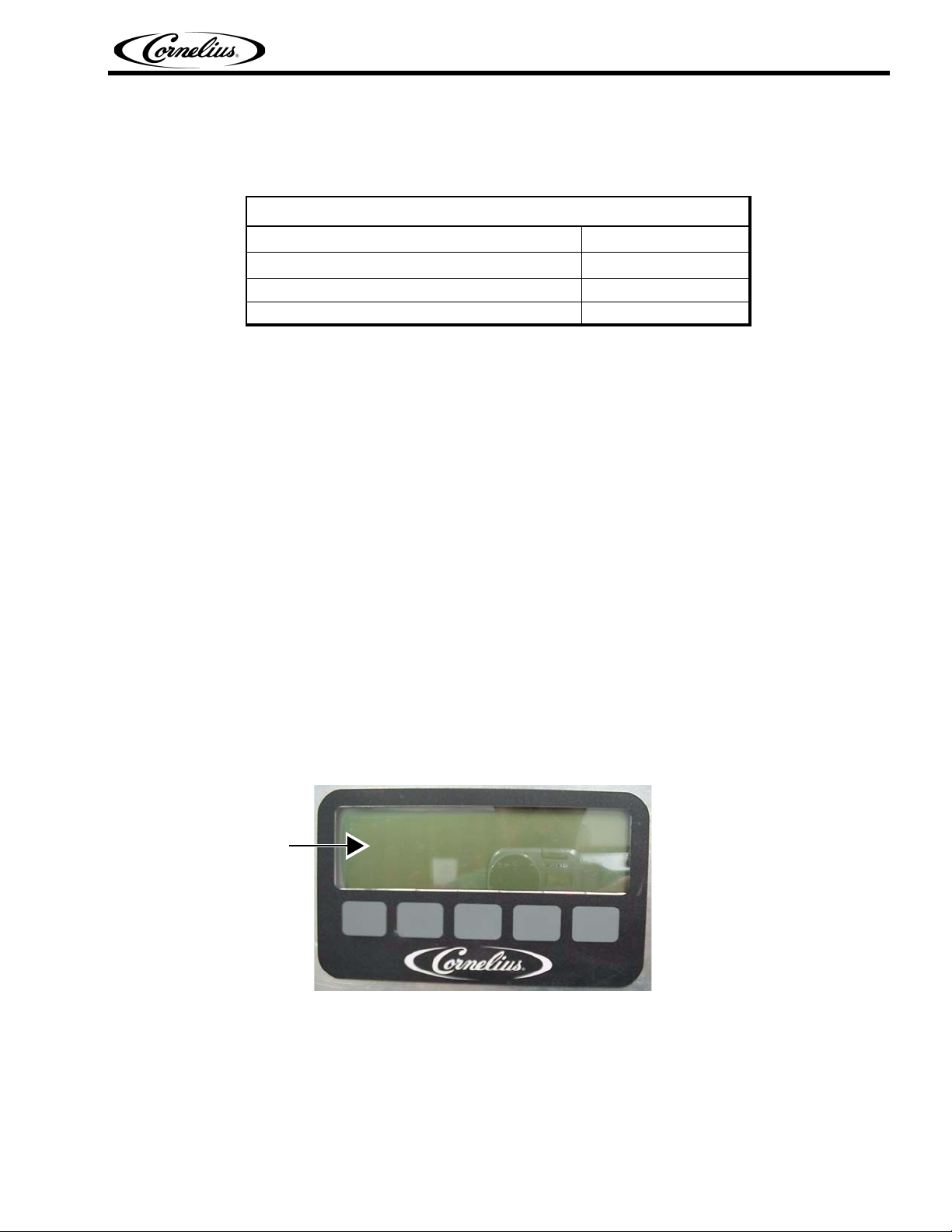
The control system is accessed with the control panel located behind the lighted merchandiser. There
are 2 levels of access to the control panel: 1 used by the operator for normal operations and 1 used by
qualified service technicians for installation and service functions. The service functions can be secured
(locked out) so that the operator will not have access to them. See the Security Lockout Function section
under menu 15 for more information.
Control Panel
Display
FIGURE 5
© 2003-2014, Cornelius Inc. - 12 - Publication Number: 560007298SER
Page 17
Pinnacle 2 and 4 Flavor Service Manual
The control panel has a variety of displays called menus. The first menu (menu #1) that is displayed is the
BARREL STATUS menu. From each menu there is a button to return to the previous menu and another
button to advance to the next menu. The menus currently programmed into the computer are the follow-
ing:
BARREL STATUS. . . . . . . . . . . . . . . . . . . . . . . . . . . . . . . . . . . . . menu 1
CHOOSE MODE . . . . . . . . . . . . . . . . . . . . . . . . . . . . . . . . . . . . . menu 2
CHANGE BARREL STATUS (ON/OFF motor) . . . . . . . . . . . . . . . menu 3
SET CLOCK . . . . . . . . . . . . . . . . . . . . . . . . . . . . . . . . . . . . . . . . . menu 4
SET WAKE UP . . . . . . . . . . . . . . . . . . . . . . . . . . . . . . . . . . . . . . . menu 5
SET SLEEP TIME . . . . . . . . . . . . . . . . . . . . . . . . . . . . . . . . . . . . menu 6
SET DEFROST (select time) . . . . . . . . . . . . . . . . . . . . . . . . . . . . menu 7
SET DEFROST (set time). . . . . . . . . . . . . . . . . . . . . . . . . . . . . . . menu 7A
VISC SET . . . . . . . . . . . . . . . . . . . . . . . . . . . . . . . . . . . . . . . . . . . menu 8
VISC DISPLAY . . . . . . . . . . . . . . . . . . . . . . . . . . . . . . . . . . . . . . . menu 9
EVAPORATOR TEMPERATURES . . . . . . . . . . . . . . . . . . . . . . . . menu 10
TOTALS . . . . . . . . . . . . . . . . . . . . . . . . . . . . . . . . . . . . . . . . . . . . menu 11
DIAGNOSTICS. . . . . . . . . . . . . . . . . . . . . . . . . . . . . . . . . . . . . . . menu 12
BARREL DATA . . . . . . . . . . . . . . . . . . . . . . . . . . . . . . . . . . . . . . . menu 13
BLENDONATOR. . . . . . . . . . . . . . . . . . . . . . . . . . . . . . . . . . . . . . menu 14
OPTIONS . . . . . . . . . . . . . . . . . . . . . . . . . . . . . . . . . . . . . . . . . . . menu 15
BRIX . . . . . . . . . . . . . . . . . . . . . . . . . . . . . . . . . . . . . . . . . . . . . . . menu 16
MANUAL DEFROST. . . . . . . . . . . . . . . . . . . . . . . . . . . . . . . . . . . menu 17
VOLT. . . . . . . . . . . . . . . . . . . . . . . . . . . . . . . . . . . . . . . . . . . . . . . menu 18
ERROR. . . . . . . . . . . . . . . . . . . . . . . . . . . . . . . . . . . . . . . . . . . . . menu 19
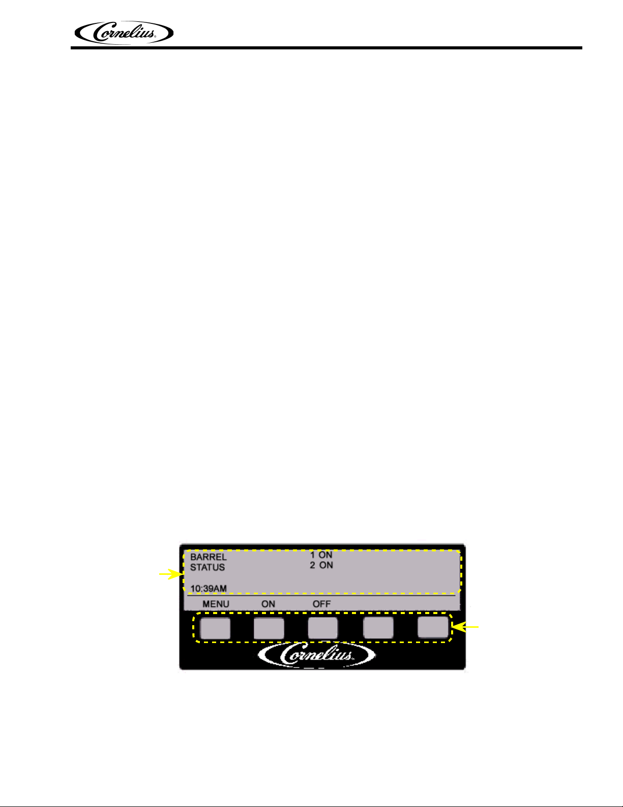
The Control Panel display has 2 main areas. The first area presents information about the status and set-
tings of the machine. It also displays menus of actions that are taken to change the functioning of the
machine.
Control Panel Display
Control Panel
Display Area
Control Panel
Action Buttons
FIGURE 6
© 2003-2014, Cornelius Inc. - 13 - Publication Number: 560007298SER
Page 18
Pinnacle 2 and 4 Flavor Service Manual
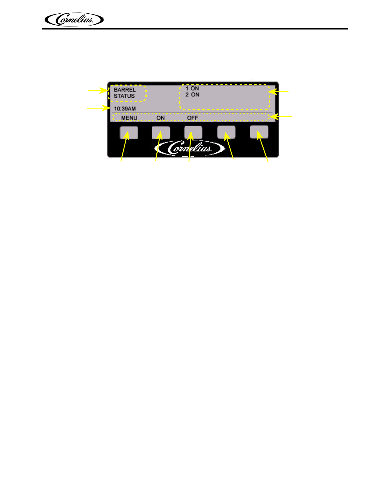
Control Panel Buttons
The second display area is the button area. There are 5 buttons that are pressed to activate various func-
tions of the control system. Each button has a label directly above it that describes what happens if that
button is pressed.
Menu
Title
System
Time
Button #1
Button #2 Button #3 Button #4 Button #5
Message
Display
Area
Button
Labels
FIGURE 7
Pressing a button performs the action labeled just above the button. For example, from the BARREL
STATUS menu, pressing button 1 (labeled MENU) displays a menu with more options — pressing button
5 (labeled ERR) displays error messages from the control system.
© 2003-2014, Cornelius Inc. - 14 - Publication Number: 560007298SER
Page 19
Control Panel Menu Descriptions
The following section describes the information displayed on each Control Panel menu and the actions
that are taken from each menu.
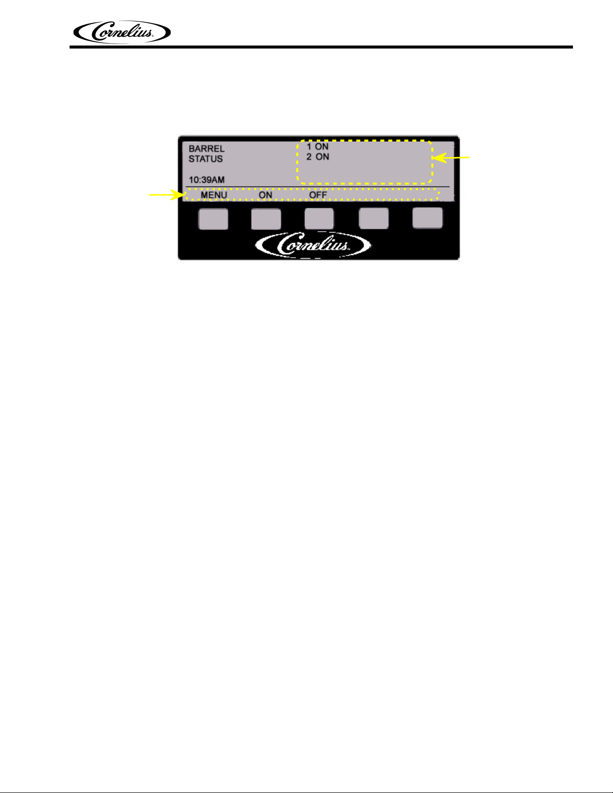
Menu 1 - BARREL STATUS
Button
Labels
The BARREL STATUS menu is the main menu of the Control Panel. This menu displays the system clock
and to the right of the words BARREL STATUS the present status of each cylinder. Listed below are the
status messages that may be displayed for each cylinder.
BARREL STATUS Menu Button Descriptions:
#1 - MENU . . . . . . . bring up the CHOOSE MODE menu (menu 2)
Pinnacle 2 and 4 Flavor Service Manual
Cylinder
Status
FIGURE 8
#2 - ON. . . . . . . . . . turn all freeze cylinders ON (beater bar TURNING and refrigeration ACTIVE)
#3 - OFF. . . . . . . . . turn all freeze cylinders OFF (beater bar OFF and refrigeration INACTIVE)
#5 - ERR . . . . . . . . Pressing ERR displays the ERROR menu which lists all system errors.
NOTE: If there are no errors, the ERR message is not displayed for button #5.
BARREL STATUS Menu Non-Error Messages:
ON . . . . . . . . . . . . . beater bar is TURNING and refrigeration to this freeze cylinder is ACTIVE
OFF . . . . . . . . . . . . beater bar is NOT TURNING and refrigeration to this freeze cylinder is
INACTIVE
MOTOR . . . . . . . . . beater bar is TURNING and refrigeration to this freeze cylinder is INACTIVE
DFRST . . . . . . . . . . freeze cylinder is presently in DEFROST mode
From the BARREL STATUS menu pressing <MENU> displays the CHOOSE MODE menu (menu 2).
NOTE: See the Control Panel Error Descriptions for a description of the system errors.
© 2003-2014, Cornelius Inc. - 15 - Publication Number: 560007298SER
Page 20
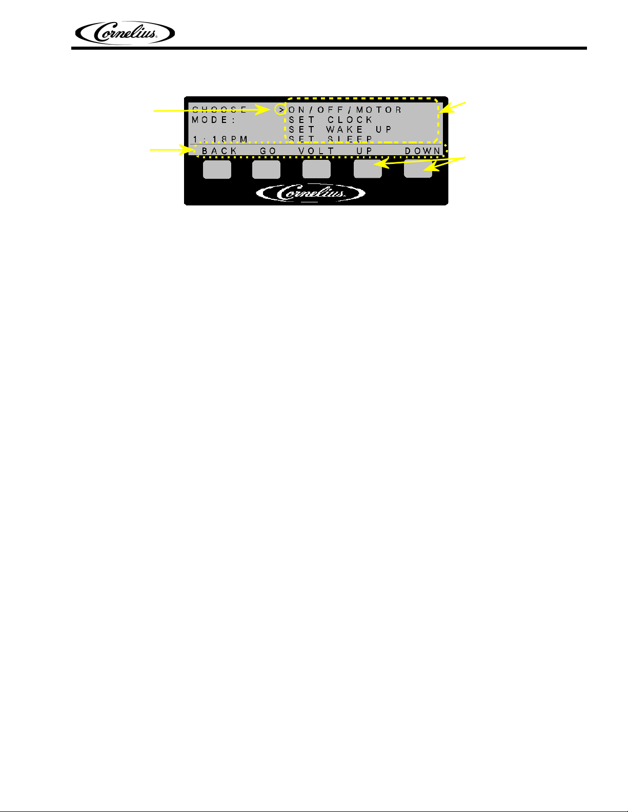
Menu 2 - CHOOSE MODE
Pinnacle 2 and 4 Flavor Service Manual
Menu
Item
Pointer
Button
Labels
FIGURE 9
Menu Scroll List
(not all items on
the list are displayed at once)
Use UP and
DOWN buttons
to scroll the list
up and down
System menus are chosen from the CHOOSE MODE menu. The VOLT menu is accessed from this
menu. The menu list is scrolled up and down pressing <UP> and <DOWN> buttons. The menu item that
has the pointer in front of it is activated when <GO> is pressed.
CHOOSE MODE Menu Button Descriptions:
#1 - BACK . . . . . . . . . . . . . . . . .go back to the BARREL STATUS menu (menu 1)
#2 - GO . . . . . . . . . . . . . . . . . . .go to the menu that is selected by the pointer
#3 - VOLT . . . . . . . . . . . . . . . . . .go to the VOLT menu (menu 19)
#4 - UP . . . . . . . . . . . . . . . . . . . .scroll up the menu list
#5 - DOWN. . . . . . . . . . . . . . . . .scroll down the menu list
CHOOSE MODE Menu Scroll List Item:
ON/OFF/MOTOR . . . . . . . . . . . .go to change BARREL STATUS menu
SET CLOCK. . . . . . . . . . . . . . . .go to SET CLOCK menu
SET WAKE UP. . . . . . . . . . . . . .go to SET WAKE UP menu
SET SLEEP . . . . . . . . . . . . . . . .go to SET SLEEP TIME menu
SET DEFROSTS . . . . . . . . . . . .go to SET DEFROST menu
VISCOSITY SET . . . . . . . . . . . .go to VISC SET Menu menu
VISC DISPLAY. . . . . . . . . . . . . .go to VISC DISPLAY menu
EVAPORATOR TEMPS . . . . . . .go to EVAPORATOR TEMPERATURE menu
TOTALS . . . . . . . . . . . . . . . . . . .go to TOTALS menu
DIAGNOSTICS . . . . . . . . . . . . .go to DIAGNOSTICS menu
BARREL DATA . . . . . . . . . . . . . .go to BARREL DATA menu
BLENDONATOR . . . . . . . . . . . .go to BLENDONATOR menu
OPTIONS . . . . . . . . . . . . . . . . . .go to OPTIONS menu
BRIX. . . . . . . . . . . . . . . . . . . . . .go to BRIX menu
MANUAL DEFROST . . . . . . . . .go to MANUAL DEFROST menu
From the CHOOSE MODE menu pressing <BACK> will display the BARREL STATUS menu and press-
ing <GO> will display the scroll list item with the pointer in front of it.
© 2003-2014, Cornelius Inc. - 16 - Publication Number: 560007298SER
Page 21
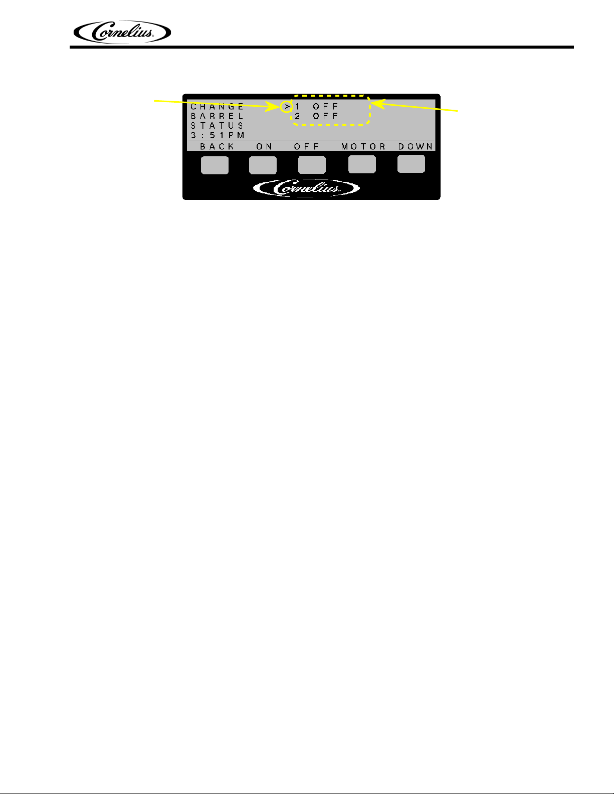
Menu 3 - CHANGE BARREL STATUS (ON/OFF/MOTOR)
Pinnacle 2 and 4 Flavor Service Manual
Menu
Item
Pointer
FIGURE 10
Cylinder Status
Messages
The CHANGE BARREL STATUS menu allows the operator to select the operational mode for each of the
cylinders on a cylinder by cylinder basis. The present status of each cylinder is also displayed (see menu
1 for a list of messages).
CHOOSE MODE Menu Button Descriptions:
#1 - BACK . . . . . . . go back to the previous menu
#2 - ON. . . . . . . . . . turn the selected cylinder “ON” (beater bar TURNING and refrigeration ACTIVE)
#3 - OFF. . . . . . . . . turn the selected cylinder “OFF” (beater bar OFF and refrigeration INACTIVE)
#4 - MOTOR. . . . . . turn the selected cylinder “MOTOR” (beater bar TURNING and refrigeration
INACTIVE)
#5 - DOWN. . . . . . . scroll down the menu list
© 2003-2014, Cornelius Inc. - 17 - Publication Number: 560007298SER
Page 22
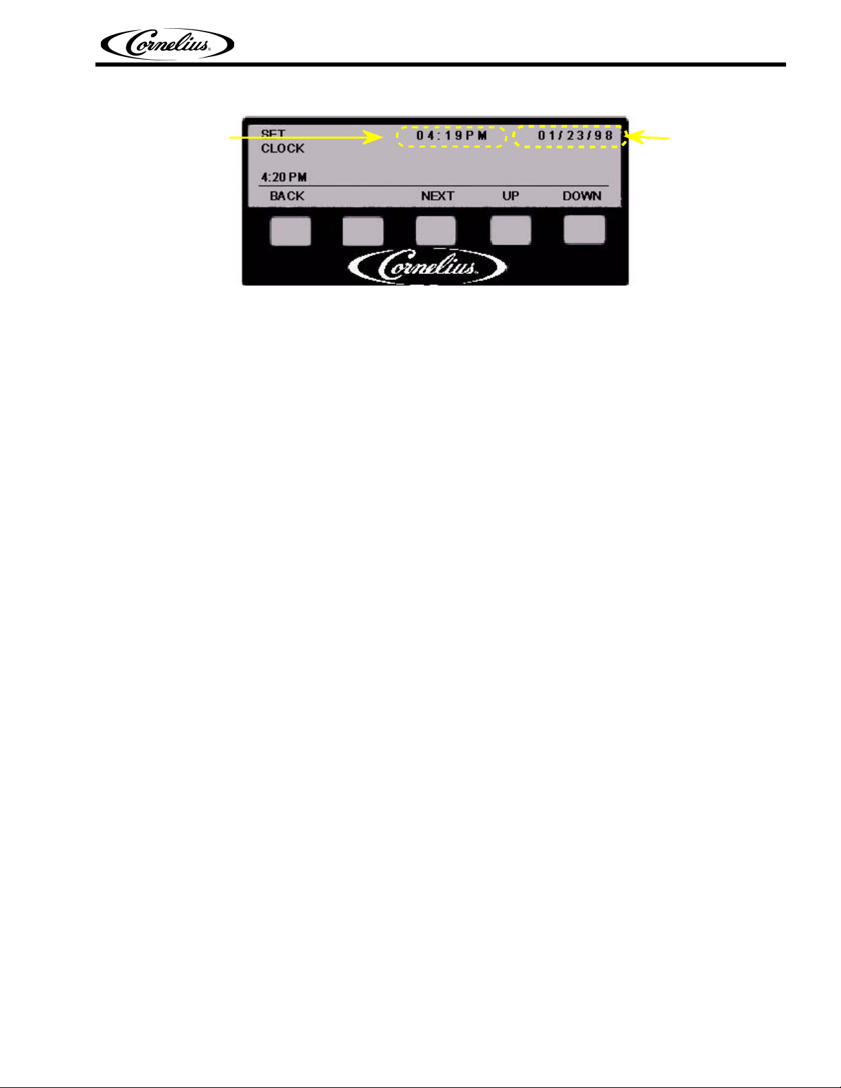
Menu 4 - SET CLOCK
Pinnacle 2 and 4 Flavor Service Manual
System
Time
FIGURE 11
System
Date
From the SET CLOCK menu the system (computer) time and date are entered or changed. The time is
displayed in 12 or 24 hour format. The time display format is selected in the OPTIONS menu (menu 15).
The date is displayed in either a US format (mm/dd/yy) or a European format (dd/mm/yy). The date dis-
play format is selected in the OPTIONS menu (menu 15).
To set the time and/or date press <NEXT> to select 1 of 6 fields (HOURS, MINUTES, AM/PM if used,
DAY, MONTH, YEAR). Press <UP> and <DOWN> to change the field. Then press <BACK> to save the
changes.
The clock can be set to automatically adjust for Daylight Savings time using the OPTIONS menu (menu
15).
SET CLOCK Menu Button Descriptions:
#1 - BACK . . . . . . . go back to the previous menu
#3 - NEXT . . . . . . . select the next field
#4 - UP . . . . . . . . . . increase the selected field by 1 (hour, day, etc.)
#5 - DOWN. . . . . . . decrease the selected field by 1
© 2003-2014, Cornelius Inc. - 18 - Publication Number: 560007298SER
Page 23
Pinnacle 2 and 4 Flavor Service Manual
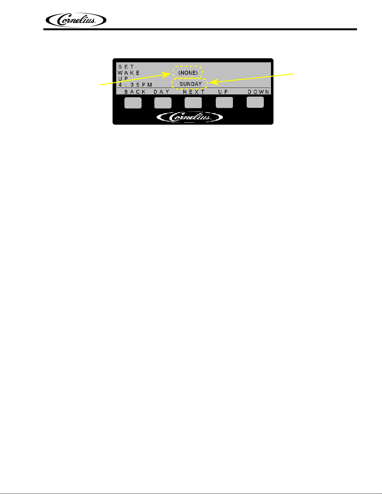
Menu 5 - SET WAKE UP
Wake Up
Wake Up
Time
FIGURE 12
Day
From the SET WAKE UP menu the system wake up times are set. These are the times when the system
will resume normal operation (freeze cylinder refrigeration and beater motor operation) after an inactive
period (sleep). Each day of the week can have a separate wake up time, or “ALL DAYS” of the week can
be programmed to wake up at the same time.
Each cylinder will wake up in the mode that it was in when it went to sleep. For instance, if cylinder #1
was ON, and cylinder #2 was in MOTOR before going to sleep, the cylinders will wake up in those modes.
Wake up times can be set in 15 minute increments. When NONE appears, it means that no wake up time
has been set for that day. The preset time format used by the system will be used by the SET WAKE UP
menu.
A WAKE UP must be set for every SLEEP.
The wake up program will run a 2 minute defrost, whether it follows a sleep or not, on each barrel before
returning the unit to normal operation.
SET WAKE UP Menu Button Descriptions:
#1 - BACK . . . . . . . go back to the previous menu
#2 - DAY . . . . . . . . . cycle through the list of days
#3 - NEXT . . . . . . . cycle through the time fields
#4 - UP . . . . . . . . . . increase the selected field by 1 hour or 15 minute increment
#5 - DOWN. . . . . . . decrease the selected field by 1 hour or 15 minute increment
To set wake up times:
1. Press <DAY> to select 1 of 8 options (SUNDAY, MONDAY, TUESDAY, WEDNESDAY, THURSDAY,
FRIDAY, SATURDAY, ALL DAYS)
2. Press <NEXT> to change the field from HOURS to MINUTES
3. Press <UP> and <DOWN> to change the setting in the field
4. Press <BACK> to save the changes.
© 2003-2014, Cornelius Inc. - 19 - Publication Number: 560007298SER
Page 24

Pinnacle 2 and 4 Flavor Service Manual
Menu 6 - SET SLEEP TIME
Sleep
Sleep
Time
FIGURE 13
Day
From the SET SLEEP TIME menu the system sleep times are set. These are the times when the system
will discontinue normal operation (cylinder refrigeration and beater motor operation). Each day of the
week can have a separate sleep time, or all days of the week can be programmed to sleep at the same
time.
An item on the OPTIONS menu (menu 15) will allow the Ice Bank to be maintained during sleep, or allow
the Ice Bank to discontinue normal operation.
Sleep times can be set in 15 minute increments. When NONE appears, it means that no sleep time has
been set for that day. The preset time format used by the system will be used by the SET SLEEP TIME
menu.
A WAKE UP must be set for every SLEEP.
See “3. Sleep Mode Recommendations” on page 7.
The merchandiser will stay ON during the SLEEP and the Motors and Barrel Refrigeration will be OFF.
The function of the ice bank during the SLEEP will depend on the setting in OPTIONS.
The unit can be manually activated by pressing ON from the main menu.
SET SLEEP TIME Menu Button Descriptions:
#1 - BACK . . . . . . . go back to the previous menu
#2 - DAY . . . . . . . . . cycle through the list of days
#3 - NEXT . . . . . . . cycle through the time fields
#4 - UP . . . . . . . . . . increase the selected field by 1 hour or 15 minute increment
#5 - DOWN. . . . . . . decrease the selected field by 1 hour or 15 minute increment
To set sleep times:
1. Press <DAY> to select 1 of 8 options (SUNDAY, MONDAY, TUESDAY, WEDNESDAY, THURSDAY,
FRIDAY, SATURDAY, ALL DAYS)
2. Press <NEXT> to change the field from HOURS to MINUTES
3. Press <UP> and <DOWN> to change the setting in the field
4. Press <BACK> to save the changes.
© 2003-2014, Cornelius Inc. - 20 - Publication Number: 560007298SER
Page 25

Menu 7 - SELECT DEFROST TIME & SET DEFROST TIME
Select
defrost
cycle
FIGURE 14
Pinnacle 2 and 4 Flavor Service Manual
Defrost Time
Number
Defrost
Time
Defrost
Day
Defrost Time
Number
Defrost
Time
Defrost
Day
FIGURE 15
From the SELECT DEFROST TIME menu the system automatic defrost cycles are set. These menus
program the automatic hot-gas defrost cycle for each freeze cylinder. The first menu sets the defrost
day(s) and the second menu sets the defrost time(s).
When ALL DAYS is selected, the defrost time entered into a specific defrost number will be scheduled for
every day of the week. When NONE appears, it means 1 of the following:
• no defrost time has been set for that defrost number;
• all of the times for that defrost number are not the same.
NOTE: All days can NOT be used to verify defrost times, only to set them.
SELECT DEFROST TIME Menu Button Descriptions:
#1 - BACK . . . . . . . go back to the previous menu
#2 - DAY . . . . . . . . . cycle through the list of days
#3 - GO . . . . . . . . . go to the second defrost menu (SET DEFROST TIME)
#4 - UP . . . . . . . . . . increase the defrost number for this day (#1-9)
#5 - DOWN. . . . . . . decrease the defrost number for this day (#1-9)
SET DEFROST TIME Menu Button Descriptions:
#1 - BACK . . . . . . . go back to the previous menu
#2 - DEF#. . . . . . . . cycle through the list of 9 defrost times per day
#3 - NEXT . . . . . . . cycle through time fields
#4 - UP . . . . . . . . . . increase item by 1 unit (hour or 15 minute segment)
#5 - DOWN. . . . . . . decrease item by 1 unit (hour or 15 minute segment)
Defrost times can be set in 30 minute increments. When NONE appears, it means that no sleep time has
been set for that day. The preset time format used by the system will be used by the SET DEFROST
TIME menu. See “3. Sleep Mode Recommendations” on page 7.
© 2003-2014, Cornelius Inc. - 21 - Publication Number: 560007298SER
Page 26

Pinnacle 2 and 4 Flavor Service Manual
Each freeze cylinder defrost cycle will terminate either when the suction temperature reaches 50°F or it
will time out after 8 minutes. There may be 9 defrost times scheduled for each of the 7 days of the week.
Cylinder 1 will begin defrosting at the set defrost time. Cylinder 2 will begin defrosting 30 minutes after
cylinder 1 began defrosting. There are no defrosts programmed from the factory.
To set defrost times:
1. Press <DAY> to select 1 of 8 options (SUNDAY, MONDAY, TUESDAY, WEDNESDAY, THURSDAY,
FRIDAY, SATURDAY, ALL DAYS).
2. Press <GO> to advance to the SET DEFROST TIME menu.
3. Press <NEXT> to change the field from HOURS to MINUTES.
4. Press <UP> and <DOWN> to change the setting in the fields.
5. Press <BACK> to save the changes.
6. If desired, repeat steps 2–5 to set more defrost times for the selected day.
7. If desired, repeat steps 1–6 to select different days and times.
© 2003-2014, Cornelius Inc. - 22 - Publication Number: 560007298SER
Page 27

Pinnacle 2 and 4 Flavor Service Manual
Menu 8 - VISC SET (Set Cylinder Viscosity)
Selection
Pointer
Cylinder
Numbers
FIGURE 16
Viscosity
Settings
The desired viscosity (thickness) of the product in each cylinder is set from this menu. The viscosity set
point can be set between 1 and 9. A viscosity setting of 1 produces a very thin watery product and a set-
ting of 9 produces a very thick icy product. The factory default is 4.
VISC SET TIME Menu Button Descriptions:
#1 - BACK . . . . . . . go back to the previous menu
#2 - ALL . . . . . . . . . sets the viscosity of all cylinders to the setting of the currently selected cylinder
#3 - GO . . . . . . . . . toggle between “cylinder selection” and “viscosity setting”
#4 - UP . . . . . . . . . . increase the selected field by 1 hour or 15 minute increment
#5 - DOWN. . . . . . . decrease the selected field by 1 hour or 15 minute increment
To change the viscosity setting for a cylinder:
1. Press <UP> or <DOWN> to select the cylinder to be adjusted. The pointer will be in front of the cur-
rently selected cylinder.
2. Press <GO> to move the selection pointer to the viscosity setting for that cylinder.
3. Press <UP> or <DOWN> to increase or decrease the viscosity setting.
4. Press <GO> to move selection pointer back to the cylinder selection.
5. Repeat steps 1 - 4 for remaining cylinders.
© 2003-2014, Cornelius Inc.. - 23 - Publication Number: 560007298SER
Page 28

Pinnacle 2 and 4 Flavor Service Manual
Menu 9 - VISC DISPLAY (Actual Cylinder Viscosity)
Actual Viscosity
Cylinder
Numbers
FIGURE 17
Reading
This menu displays the actual viscosity value for each cylinder. The smaller the number the lower the vis-
cosity (thinner product).
VISC DISPLAY Menu Button Descriptions:
#1 - BACK . . . . . . . go back to the previous menu
The table below identifies the maximum and minimum viscosity values for specific viscosity settings. For
example, with a viscosity setting of 2, the system calls for refrigeration when the viscosity drops below 43.
Refrigeration continues until the viscosity reaches 60 when leveling begins.
NOTE: There is a 2 minute timer to prevent the compressor from short cycling. This timer is can-
celed out by a Blendonator actuation.
Viscosity Setting
Maximum Viscosity
Val ue
Minimum Viscosity
Val ue
15036
26043
37058
48068
59078
610086
711096
8120106
9130116
© 2003-2014, Cornelius Inc. - 24 - Publication Number: 560007298SER
Page 29

Menu 10 - EVAPORATOR TEMPERATURES
Pinnacle 2 and 4 Flavor Service Manual
Cylinders
Fahrenheit
or Celsius
Ice Bank
FIGURE 18
Input & Output
Temperatures
The input and output temperatures of each system evaporator (both product freeze cylinders and ice
bank) are displayed. In the display the IN represents the inlet temperature and the OUT represents the
outlet temperature. The temperature scale used (°F or °C) is based on your input in the OPTIONS menu
(menu 15). The maximum temperatures are 97°F for the barrels (BRL #1 or #2) and 48°F for the ice bank
(IB #1). The minimum temperatures for both the barrel and ice bank is -30°F.
EVAPORATOR TEMPERATURES Menu Button Descriptions:
#1 - BACK . . . . . . . go back to the previous menu
© 2003-2014, Cornelius Inc. - 25 - Publication Number: 560007298SER
Page 30

Menu 11 - TOTALS
Pinnacle 2 and 4 Flavor Service Manual
Selection
Pointer
Item or
Subsystem
FIGURE 19
Totals (see
chart below)
The TOTALS menu displays operational totals for the system. The totals tracked by the computer are
listed below. Those totals marked with an * can be reset to zero. The RESET button will only appear
when the reset option is enabled.
The reset option is enabled/disabled from the OPTIONS menu (menu 15).
TOTALS Menu Button Descriptions:
#1 - BACK . . . . . . . go back to the previous menu
#4 - UP . . . . . . . . . . scroll totals list up
#5 - DOWN. . . . . . . scroll totals list down
TOTALS Menu Messages:
POWER ON . . . . . . xxxxx HRnumber of hours the system has been powered ON
SLEEP . . . . . . . . . . xxxxx HRnumber of hours system has been in SLEEP mode
COMP #n . . . . . . . . xxxxx HR*number of hours compressor “n” has run
COMP #n . . . . . . . . xxxxx CYC*number of run cycles compressor “n” has performed
AGITAT #n . . . . . . . xxxxx HR*number of hours agitator motor “n” has run
BRL ON #n. . . . . . . xxxxx HRnumber of hours cylinder “n” has been in ON mode
MOTOR #n . . . . . . . xxxxx HR*number of hours cylinder motor “n” has run
SYRUP #n . . . . . . . xxxxx MIN*number of minutes syrup flow “n” has been called for
ERROR #n . . . . . . . xxxxx HR*number of hours cylinder “n” has had any errors
SYR SO #n. . . . . . . xxxxx HRnumber of hours cylinder “n” is out of syrup
DEFRST #n . . . . . . xxxxx HRnumber of hours cylinder “n” has been in auto defrost
BLENDR #n . . . . . . xxxxx HRnumber of blender cycles on cylinder “n”
* = resetting these totals to zero is allowed
© 2003-2014, Cornelius Inc. - 26 - Publication Number: 560007298SER
Page 31

Pinnacle 2 and 4 Flavor Service Manual
Menu 12 - DIAGNOSTICS
Selection
Pointer
Item or
Subsystem
FIGURE 20
The DIAGNOSTICS menu allows the selection of manual or automatic display of system information. The
manual mode allows the operator to select which output is activated. The automatic mode cycles through
all of the outputs 1 after the other.
The automatic mode begins at the selection pointer and stops at the end of the list or when the AUTO is
pressed again. The automatic mode cycles through each output for 2 seconds ON and 3 seconds OFF.
The output list scrolls down as the automatic mode progresses.
All system functions and controls are disabled/terminated during the diagnostic mode.
The diagnostic display order is organized on a cylinder-by-cylinder basis. All outputs associated with a
specific cylinder displayed as a group. When that cylinder is done the next cylinder group will begin. After
the cylinders the ice banks information is displayed on an ice bank by ice bank basis.
DIAGNOSTICS Menu Button Descriptions:
#1 - BACK . . . . . . . go back to the previous menu
#2 - AUTO . . . . . . . toggle begin/end of automatic mode
#3 - EXEC . . . . . . . activate the output at the selection pointer
#4 - UP . . . . . . . . . . scroll list up
#5 - DOWN. . . . . . . scroll list down
DIAGNOSTICS Menu Messages:
AUDIBLE ALARM. . activate audible alarm on display board
Cylinder Group #X:
BRL PULSE VLV #Xactivate cylinder pulse valve
H20 SOLENOID #X activate water solenoid
DEFROST VLV #X activate cylinder defrost valve
DISP VALVE LO #X activate dispense valve lockout
CARB MTR PUMP #Xactivate carbonator pump motor
SYR SOLENOID #Xactivate syrup solenoid
BEATER MOTOR #Xmake beater motor turn
BRL STAT LITE #X activate cylinder status light (red & green)
AUDIBLE ALARM . activate audible alarm on main logic board
© 2003-2014, Cornelius Inc. - 27 - Publication Number: 560007298SER
Page 32

Pinnacle 2 and 4 Flavor Service Manual
Menu 13 - BARREL DATA
Information
Items
FIGURE 21
The BARREL DATA menu displays information about major system components for each cylinder.
BARAL DATA Menu Button Descriptions:
#1 - BACK . . . . . . . go back to the previous menu
#4 - UP . . . . . . . . . . scroll list up
#5 - DOWN. . . . . . . scroll list down
BARREL DATA menu information:
BARREL # . . . . . . . status of cylinder #n (ON, OFF, MOTOR, DEFROST, ERROR)
EVAPS IN . . . . . . . evaporator temperature IN
EVAPS OUT . . . . . evaporator temperature OUT
VISC SET. . . . . . . . viscosity set value
ACT . . . . . . . . . . . . actual viscosity value
BLENDONATOR . . blendonator mode (ON, OFF)
© 2003-2014, Cornelius Inc. - 28 - Publication Number: 560007298SER
Page 33

Menu 14 - BLENDONATOR (Blendonator Status)
Pinnacle 2 and 4 Flavor Service Manual
Cylinder
Number
Selection
Pointer
FIGURE 22
Fill Mode
Status
The BLENDONATOR menu allows the selection of automatic blendonator tank filling. With automatic
mode ON the blendonator tank will fill when the float drops.
Scroll the selection pointer to the desired cylinder number and press <ON> or <OFF> to turn the auto-
matic filling ON or OFF.
BLENDONATOR Menu Button Descriptions:
#1 - BACK . . . . . . . go back to the previous menu
#2 - ON. . . . . . . . . . turns blendonator automatic fill mode ON
#3 - OFF. . . . . . . . . turns blendonator automatic fill mode OFF
#4 - UP . . . . . . . . . . move selection pointer up
#5 - DOWN. . . . . . . move selection pointer down
© 2003-2014, Cornelius Inc. - 29 - Publication Number: 560007298SER
Page 34

Pinnacle 2 and 4 Flavor Service Manual
Menu 15 - OPTION SELECT STATUS
Option
Name
Option
Status
FIGURE 23
The OPTION SELECT STATUS menu allows system options to be selected and customized. These
options will be displayed on the OPTIONS menu.
OPTION SELECT STATUS Menu Button Descriptions:
#1 - BACK . . . . . . . go back to the previous menu
#2 - OPTION #1 . . . select this option (the button label changes depending on the option being displayed)
#3 - OPTION #2 . . . select this option (the button label changes depending on the option being displayed)
#4 - UP . . . . . . . . . . scrolls list up
#5 - DOWN. . . . . . . scrolls list down
To display, select, and change system options:
1. Press <UP> or <DOWN> to select the desired option
2. Press the <OPTION #1> button to change that option
3. Press the <OPTION #2> button to change that option
4. Press <UP> or <DOWN> to display the next option.
The options that can be displayed and changed are described below.
Option Name Button #1 Button #2 Description
DAYLT SAVINGS NO YES disable/enable Daylight Savings Time
CELCIUS/FAHREN FAHR CELS select temperature for display
DATE FORMAT USA EURO selects date format (U.S. mm/dd/yy or European dd/
mm/yy)
TIME FORMAT 12HR 24HR selects 12 hour (AM/PM) or 24 hour time format
SECURITY OFF ON disable/enable security lockout of system parameters
LANGUAGE ENGL OTHER select language (as available)
VALVE LOCK OUT DISAB ENAB Not Used
RESET TOTALS DISAB ENAB disable/enable resetting of totals in the TOTALS menu
ICE BANK/SLEEP OFF ON Ice Bank and Ice Bank Agitator remains OFF/ON while
system is sleeping
KEY BEEP OFF ON turns beeping of key inputs OFF/ON
SYRUP SOURCE BOX TANKS What is source of syrup. TANKS will enable “Syrup
Prime” on syrup sold out.
Security Lockout Function:
The security function is enabled in the OPTION SELECT STATUS menu. When the security lockout is
enabled, lockout will engage 15 minutes after last button press. Once lockout is engaged the display goes
to BARREL STATUS menu, and the MENU button (#1) is disabled. Security is disengaged by pressing
button #1 (far left) and #5 (far right) at the same time.
© 2003-2014, Cornelius Inc. - 30 - Publication Number: 560007298SER
Page 35

Menu 16 - BRIX
Pinnacle 2 and 4 Flavor Service Manual
Cylinder
Number
Selection
Pointer
BRIX
Status
FIGURE 24
The BRIX menu allows the activation of syrup and water solenoids, and blendonator pump motor for a
selected cylinder.
PRESSURE SWITCH AND
WATER
FLOW REGULATOR
AND SOLENOID VALVE
SYRUP
SOLD-OUT SWITCH
WATER REGULATOR
SINGLE
CHECK
VALV E
PRODUCT PUMP
(SYRUP AND WATER
ARE MIXED)
PRODUCT SAMPLE VALVE
COOLING COIL
DOUBLE
CHECK
VALV E
WATER ICE BATH
FREEZE
CYLINDER
PRODUCT SHUTOFF
VALV E
BLENDONATOR
FIGURE 25
1. Make sure the status of all cylinders is OFF on the display.
2. Turn product supply valve to the 90 degree (OFF) position for the barrel you are using. It is
recommended to close both valves to be sure the correct valve is chosen.
3. Press MENU. Then press UP repeatedly until BRIX is displayed. Press GO and select cylinder you
wish to Brix. NOTE: Pressing CANCEL will stop the process.
4. Locate the appropriate (correct barrel) sample tube and hold a cup under it.
NOTE: If Product Sample Valve is located in a different position then FIGURE 25 see the
schematics in Appendix A for the two alternate constructions (section 1 and 2) and their
respective Brixing instructions.
5. Open the valve at the end of the sample tube. Press GO and wait 3-5 seconds. The product pump
will pump product for approximately 3 seconds. After sample is dispensed Press Go twice more to
dispense product two more times. Discard these first three samples.
© 2003-2014, Cornelius Inc. - 31 - Publication Number: 560007298SER
Page 36

Pinnacle 2 and 4 Flavor Service Manual
6. Press GO again. Collect sample from cup and close valve at end of sample tube. Place adequate
amount on refractometer and read Brix. A target Brix reading of 13.0 (+/- 1.0) is normally desired for
sugar-based syrups. Lower values for some diet syrups can be specified. Check with the syrup
manufacturer if you are not sure.
7. If reading is out of specification the syrup level needs to be adjusted. NEVER change the WATER
FLOW CONTROL setting to adjust Brix (FIGURE 26).
Syrup Flow Control
Water Flow Control
FIGURE 26
8. To increase Brix reading, turn syrup regulator clockwise. Turn counter-clockwise to decrease Brix.
Adjust flow control in no more than ½-turn increments. Repeat steps 4 through 6 for each
adjustment until desired Brix setting is achieved.
9. After finishing step 8 for first barrel, repeat steps 1 through 8 for next barrel.
NOTE: If Brix percent cannot be set in step 8, check the water flow rate. To do this verify flow in
cup is at least 6.3 to 6.9 oz. (186 to 204 ml) in 3 seconds.
NOTE: If water flow is low, boost incoming water pressure.
BRIX Menu Button Descriptions:
#1 - BACK . . . . . . . go back to the previous menu
#2 - GO . . . . . . . . . turn ON syrup and water solenoids, and blendonator pump for selected cylinder
for 3 seconds
#3 - CANCL . . . . . . turn OFF syrup and water solenoids, and blendonator pump for selected cylinder
#4 - UP . . . . . . . . . . move selection pointer up
#5 - DOWN. . . . . . . move selection pointer down
© 2003-2014, Cornelius Inc. - 32 - Publication Number: 560007298SER
Page 37

Pinnacle 2 and 4 Flavor Service Manual
Menu 17 - MANUAL DEFRST
Cylinder
Number
Selection
Pointer
FIGURE 27
Defrost
Status
The MANUAL DEFRST menu allows the activation of 2 minute manual defrost mode for a selected cylinder. This defrost cycle can begin with the cylinder in any mode (ON, OFF, Motor) and will return the cylinder to that same mode. Manual defrost can be activated on only 1 cylinder associated with a compressor
at a time.
The description of the button 2 will change based on the status of the selected cylinder. When not in
defrost, button 2 will read DFRST. When in defrost, button 2 will read CANCL.
Pressing DFRST will begin a manual defrost on the selected cylinder, and pressing CANCL will end the
manual defrost on the selected cylinder.
MANUAL DEFRST Menu Button Descriptions:
#1 - BACK . . . . . . . go back to the previous menu
#2 - DRFST . . . . . . begin manual defrost on selected cylinder (defrost will last approx 2 minutes)
#4 - UP . . . . . . . . . . move selection pointer up
#5 - DOWN. . . . . . . move selection pointer down
© 2003-2014, Cornelius Inc. - 33 - Publication Number: 560007298SER
Page 38

Pinnacle 2 and 4 Flavor Service Manual
Menu 18 - VOLT
Voltage
FIGURE 28
The VOLT menu displays line voltage at the contactor. The voltage will be displayed in Volts RMS.
VOLT Menu Button Descriptions:
#1 - BACK . . . . . . . go back to the previous menu
© 2003-2014, Cornelius Inc. - 34 - Publication Number: 560007298SER
Page 39

Pinnacle 2 and 4 Flavor Service Manual
Menu 19 - ERROR
FIGURE 29
The ERROR menu displays a list of errors that are presently on the system. All system errors will be displayed on this list in the priority order. The error list will scroll if necessary. The display of the error list will
be updated every 3 seconds.
The RESET function will silence the beeper (if sounding), and reset the errors that are capable of MANUAL ERROR RESET. As “automatically” correctable errors are satisfied, the error list will reflect this
when updated.
NOTE: The Syrup Sold Out condition is not effected by the RESET button.
ERROR Menu Button Descriptions:
#1 - MENU . . . . . . go back to the previous menu
#2 - ON. . . . . . . . . . go to SYRUP SOLD OUT menu
#3 - OFF. . . . . . . . . begin MANUAL ERROR RESET
#4 - UP . . . . . . . . . . scrolls list up
#5 - DOWN. . . . . . . scrolls list down
Error History Log Information
FIGURE 30
The error history log records errors to diagnose potential issues. The error log will retain information on
the 50 most recent sets of events. All errors dated will have occurred during testing and set up. This is a
default that is used before the time clock is programmed.
The error log history is only accessible from the BARREL STATUS menu. To enter the error history you
must press the 2 far right buttons on the display panel. This will bring up the error history log menu and
the most recent event will be displayed. PREV moves you backwards in the list of events and NEXT
moves you forwards in the list of events.
The error history can be accessed while the security lock out is activated. To return to the main menu
press BACK.
#1 - BACK . . . . . . . go back to the BARREL STATUS menu
#4 - NEXT . . . . . . . display the next (later) error log entry
#5 - PREV . . . . . . . display previous (earlier) error log entry.
© 2003-2014, Cornelius Inc. - 35 - Publication Number: 560007298SER
Page 40

Control Panel Error Descriptions
The following section describes the error messages displayed on the Control Panel, the error priority, and
the appropriate actions to be taken.
Errors are displayed on the following menus:
• Main menu (BARREL STATUS) - menu 1
• ON/OFF/MOTOR menu (CHANGE BARREL STATUS) - menu 3
• BARREL DATA menu - menu 13
• SET DEFROST menu - menu 17
• ERROR menu - menu 20
Errors are displayed in the above menus differently. The response to error conditions are listed below.
COMO Error: There is no communication between the J1 connector on the display board and the J17
connector on the main board.
ELECTRONICS Error: Means 1 of 2 things:
• Communication has been not established or broken between the main board and 1 or more of the
product delivery boards for ten consecutive communication cycles.
• Failure of the real time clock chip. The new controls will display a “CLOCK ERROR” message.
HOT GAS Error X: Indicates that the barrel outlet sensor for barrel X exceeded 120°F for 2 minutes.
Do not restart unit. Immediately call Service at (800) 238-3600.
HIGH VOLTAGE GENERATED Errors: It is possible to generate Electronic or Como errors by routing
phone lines or low voltage communication lines in the vicinity of high voltage components on the Inverter
Board.
LOW VOLTAGE GENERATED Errors: It is also possible to generate these errors if low voltage communication wires or phone cables are in the vicinity of the Inductor on the Main Board. That would be the
black capacitors on the Invertor Board and the wire wrapped coil on the Main Board.
LOW or HIGH VOLTAGE Error: This message means that the incoming voltage is out of specification
(180V to 260V) for the unit.
Pinnacle 2 and 4 Flavor Service Manual
LOW VOLTAG E E r ro r : If the voltage at the junction box is good, high voltage may not be getting up to the
main board. Check this voltage at J10 on the main board. If the voltage is good at the board and the low
voltage error remains, main board is bad. Display voltage to be
±5 VAC from measured J10 Voltage.
DRIVE Error: The motor has been commanded to rotate but will not rotate.
OVER TORQUE Error: This error occurs when the motor load is greatly increased and causes the barrel
viscosity to be more than 250 and the motor is still turning. It can also occur when the inverter board has
a problem. If the viscosity is less than 25 with the motor running, the high viscosity reading could have
been because of a mechanical load.
REFRIG Error: Means that a specific evaporator has NOT been satisfied within a set time limit. The
entire refrigeration system will be disabled. The REFRIG error time limits are:
• Freeze Barrel: 46 minutes; Ice Bath: 120 minutes for 60Hz or 240 minutes for 50Hz.
SYRUP Error: Syrup supply empty.
CO2 Error: Carbon dioxide supply empty.
H2O Error: Water supply empty.
SENSOR Error: Means that a thermal sensor (thermistor) is not functioning properly.
During a refrigeration cycle, if a barrel sensor’s reading is at 97
o
F or at -30oF for more than 600 seconds,
the control system will display a SENSOR ERROR for that evaporator. During a refrigeration cycle, if a
ice bank sensor’s reading is at 49
o
F or at -30o F for more than 2400 seconds, the control system will dis-
play a SENSOR ERROR for the Ice Bank.
NOTE: The 5600075xx Series controls will have an upper limit of 150°F for barrel sensors.
© 2003-2014, Cornelius Inc. - 36 - Publication Number: 560007298SER
Page 41

3 - The “Cylinder Status Light” of the affected cylinder will flash green at a 1 Hz rate (50% DC) on all errors.
4 - The Blender will NOT respond to float activations wen “OFF”, and will respond when “ON” only is previously enabled.
1 - The “motor condition means the motor will continue operating if it was in operation prior to the error. If the motor was OFF it will remain OFF.
2 - The “Beeper” will give a 5 beep sequence for each new error that occurs after a beeping sequence is completed.
Pinnacle 2 and 4 Flavor Service Manual
** - The compressor associated with this freeze cylinder/ice bank will stop providing cooling to this specific evaporator.
Footnotes:
* - The compressor associated with this refrigeration system where the error occurs will be commanded OFF (not “no longer needed).
Ice Bank Sensor 10 Manual IB OFF** OFF OFF “Last Known
Cylinder Sensor 10 Manual Cylinder
H2O Sold Out 9 Auto OFF* Motor OFF “Last Known
CO2 Sold Out 8 Auto OFF* Motor OFF “Last Known
Syrup Sold Out 7 Auto Cylinder
Ice Bank Refg 6 Manual OFF* OFF ON “Last Known
Cylinder Refg 5 Manual OFF* OFF ON “Last Known
Over Torque 4 Manual Cylinder
Cylinder Drive 3 Manual Cylinder
Low Voltage 2b Auto OFF* OFF OFF “Last Known
Real Time Clock 1c Cycle
Hot Gas Valve 1d Cycle
High Voltage 2a Auto OFF* OFF OFF “Last Known
Electronics 1b Cycle
Communication 1a Cycle
Error
Priority
Response
Power
Power
Power
Power
OFF**
OFF**
OFF**
OFF**
OFF* OFF OFF
OFF* OFF OFF OFF CLOCK
OFF* OFF OFF OFF COMMO COMMUNICATION
OFF* OFF OFF OFF ERROR ELECTRONICS
Display
Error Reset
Comp
OFF OFF “Last Known
Motor OFF “Last Known
OFF ON “Last Known
OFF ON “Last Known
OFF
Motor
1
Blend
System Response Display Output
State” of System
State” of System
SENSOR IB SENSOR #Y
SENSOR BRL SENSOR #X
State” of System
H2O H2O OUT
State” of System
State” of System
CO2 CO2 OUT
SYRUP SYRUP #X
State” of System
4
State” of System
State” of System
State” of System
State” of System
State” of System
OFF HOT GAS #X HOT GAS #X
Condition After
Error Reset
REFRIG IB REFRIG #Y
REFRIG BRL REFRIG #X
TORQUE TORQUE #X
DRIVE DRIVE #X
VOLT LOW VOLTAGE
VOLT HIGH VOLTAGE
ERROR
Menu 1,3,13,17 Menu 20
CLOCK ERROR
© 2003-2014, Cornelius Inc. - 37 - Publication Number: 560007298SER
Page 42

COMPONENT SERVICE
NOTE: IF the LED on display panel is ON please see Tech Tip TT-04-13, on www.cornelius.com, for
information on the Production Safety System Response.
The following are procedures for servicing the major components of the Pinnacle.
MAGNET ASSEMBLY REPLACEMENT
1. Defrost the cylinder.
2. Turn the blendonator OFF.
3. Drain the cylinder by opening the dispensing valve. When
only CO
valve off. Relieve CO
pressure relief valve.
4. Remove the cylinder face plate (4 nuts and washers).
comes out, turn the cylinder product supply
2
pressure by opening the faceplate
2
Pinnacle 2 and 4 Flavor Service Manual
Relieve CO2 pressure
5. Remove beater bar and scraper blades.
6. Use the magnet puller tool (p/n 560003662) that comes
with the unit to remove the magnet.
NOTE: Sufficient force must be used to break the magnet lose from the end of the cylinder.
CAUTION — The magnet is very strong,
heavy, and fragile. Be careful not to pinch hands
and fingers between the magnet and a steel
object. Make sure no foreign objects are attached
to the magnet.
WARNING — Strong Magnetic Field.
Person wearing pacemaker, implanted cardioverter defibrillator, or other implanted medical
device may be affected by the magnetic field and
must keep the magnet at 6 or more inches from the device.
The magnetic field can affect operation of these devices
which may cause bodily injury or death.
If disruption of device occurs or operation is adversely
effected, immediately move the victim far away from magnet and seek medical assistance.
Remove nuts (x4)
FIGURE 30
Tool hooks
into magnet
FIGURE 31
© 2003-2014, Cornelius Inc. - 38 - Publication Number: 560007298SER
Page 43

7. Install the magnet in the reverse order to removing it. Use
the magnet puller tool to install the magnet being careful
to insert the magnet slowly and not let it slam into the end
of the cylinder.
Pinnacle 2 and 4 Flavor Service Manual
Magnet removal tool
DO NOT let magnet slam into end of cylinder
FIGURE 32
8. Inspect parts to see if they should be replaced, including
the beater bars, face plate, O-ring, and beater bar
bushing.
NOTE: Install faceplate by pressing until it contacts the
front of the cylinder. Reinstall 4 washers and nuts finger
tight. Then approximately 1/4 turn with a wrench.
9. When all the hardware is securely in place turn the
blendonator ON, then turn the product cylinder supply
valve ON, bleed the cylinder, and use the control panel to
turn the cylinder ON. There is a short delay before the
beater bar starts rotating.
Align
notched
hole in
beater bar
with
notched
rod on
shaft
FIGURE 33
Make sure
bushing on face
plate/beater bar
shaft is in good
condition
FIGURE 34
© 2003-2014, Cornelius Inc. - 39 - Publication Number: 560007298SER
Page 44

Pinnacle 2 and 4 Flavor Service Manual
DC CONTROL DRIVE MOTOR BOARD REPLACEMENT - EMERSON
CAUTION - Use a grounding strap.
1. Disconnect the power to the unit.
DC Control
Drive Motor
Board
FIGURE 35
2. Open the merchandiser door, then remove the top front panel and front hinged panel.
DANGER — HIGH VOLTAGE, after disconnecting power wait for approximately 5 minutes to
work on the unit. Working on the unit before the 5 minutes have passed could result in electrical
shock or death!
3. Unscrew the 3 mounting screws on the Control Drive Motor board mounting bracket and slide the bracket
up while tilting it out. Do NOT detach the wires from the board yet.
4. Secure the new board in place. One at time remove the wires from the old board and connect them to the
new board. Make sure that the thermistor harness is not removed with the old board.
5. Connect the power.
6. Re-attach the panels.
MAIN AND PRODUCT DELIVERY BOARD REPLACEMENT - EMERSON
1. Disconnect the power to the unit.
2. Open the merchandiser door then remove top front panel
and front hinged panel.
DANGER — HIGH VOLTAGE, after discon-
necting power wait approximately 5 minuets to
work on the unit. Working on the unit before the 5
minutes have passed could result in electrical
shock or death!
3. Remove all wires from board being replaced.
4. Disconnect the 4 mounting standoffs and remove the
board.
5. Secure the new board in place and reconnect the wiring.
6. If the Main Board was replaced, program the previous
setting for time, defrost, sleep, walk-up, and viscosity.
7. Re-attach the panels.
Product Delivery
Boards
DC Control Drive
Motor Boards
Main Boards
FIGURE 36
Product Delivery
Boards
© 2003-2014, Cornelius Inc. - 40 - Publication Number: 560007298SER
Page 45

CHIP CHANGE PROCEDURE
The purpose of this notice is to describe the proper method for changing a chip on the master board of a
Cornelius machine should it become necessary.
NOTE: Static electricity can destroy sensitive electronic circuits. Always wear static straps or
keep yourself grounded to the machine while working in the electronic boards.
Tools needed:
• 32 pin dip extractor (chip puller) 790327
Wrist ground strap 790326
1. Unplug machine.
2. Remove top panel on floor models. Open door to access the control box on the OC2 machine.
3. Remove lid to control box on.
4. Place the chip puller and new chip on the machine (chip still in the container).
5. Attach ground strap to the bare metal control box.
6. Carefully remove the new chip from shipping container. Save shipping container to pack old chip in.
7. Place chip puller on chip and gently squeeze until tool grips the chip.
8. Pull the chip puller straight up with a gentle end–to–end rocking motion to remove the chip. Place old
chip in the original container.
9. Pull the chip puller straight up with a gentle end–to–end rocking motion to remove the chip. Place old chip in the original container.
Pinnacle 2 and 4 Flavor Service Manual
10. Carefully place new chip in the socket and make sure all pins are started in their holes. Press firmly
straight down on the chip until it is fully engaged in the socket. Note: Proper placement of the chip
can be confirmed by aligning the small indent on one end of the chip with the indent on the outline
that is drawn on the board.
11. Remove ground strap.
12. Replace control box lid.
13. Replace top machine panel or close access door.
14. Plug in machine.
15. Defrost both barrels.
16. Check Viscosity read. If both sides read 0 go to 17.
17. If either side reads other than 0, beater motor currents needs to be reset.
18. Turn machine on auto and check for normal operation.
19. Secure machine.
© 2003-2014, Cornelius Inc. - 41 - Publication Number: 560007298SER
Page 46

Pinnacle 2 and 4 Flavor Service Manual
P
DC INVERTER BOARD REPLACEMENT - BALDOR
CAUTION - Use a grounding strap.
1. Disconnect the power to the unit.
DC Inverter board (Baldor)
D33 light (Baldor)
FIGURE 37
2. Open the merchandiser door, then remove the top front panel and front hinged panel.
DANGER — HIGH VOLTAGE, after disconnecting power wait for the D33 red light to go out indi-
cating that it is safe to work on the unit. Working on the unit when the red D33 light is lit could result
in electrical shock or death!
3. Unscrew the 4 mounting screws on the DC inverter board mounting bracket and slide the bracket up while
tilting it out. Do NOT detach the wires from the board yet.
4. Secure the new board in place. One at time remove the wires from the old board and connect them to the
new board.
5. Connect the power and check that the D33 light comes on.
6. Re-attach the panels.
MAIN AND PRODUCT DELIVERY BOARD REPLACEMENT - BALDOR
1. Disconnect the power to the unit.
2. Open the merchandiser door then remove top front panel
and front hinged panel.
DANGER — HIGH VOLTAGE, after discon-
necting power wait for the D33 red light to go out
indicating that it is safe to work on the unit. Work-
result in electrical shock or death!
3. Remove all wires from board being replaced.
ing on the unit when the red D33 light is lit could
Product Delivery
Boards
Inverter Boards
(Emerson
roduct Delivery
Boards
4. Disconnect the 4 mounting standoffs and remove the
board.
5. Secure the new board in place and reconnect the wiring.
Main Boards
FIGURE 38
6. If the Main Board was replaced, program the previous setting for time, defrost, sleep, walk-up, and
viscosity.
7. Re-attach the panels.
© 2003-2014, Cornelius Inc. - 42 - Publication Number: 560007298SER
Page 47

Pinnacle 2 and 4 Flavor Service Manual
DISPLAY BOARD REPLACEMENT
1. Disconnect the power to the unit.
2. Open the merchandiser door then remove top front panel and hinged panel.
DANGER — HIGH VOLTAGE, after disconnecting power wait for the D33 red light to go out indi-
cating that it is safe to work on the unit. Working on the unit when the red D33 light is lit could result
in electrical shock or death!
3. Unscrew the 4 screws holding the board cover. Carefully reach behind the cover and disconnect the wires
(ribbon cable, phone cable, power cable).
Mounting
standoff (4)
Display
Board
4. Remove the board from the 4 standoffs.
Cover
FIGURE 39
5. Install the new board with the ribbon cable protruding
through the top.
Ribbon cable
FIGURE 40
6. Reconnect the wires while installing the cover.
7. Connect the power and check to see that the control panel works properly. Secure the circuit board door
and follow a normal startup procedure.
8. Re-attach the panels.
NOTE: The error log is stored on the display board.
MERCHANDISER LIGHT BALLAST REPLACEMENT
1. Disconnect the power to the unit.
2. Lift the merchandiser and slide it left or right to lock it in
place.
3. Remove the ballast cover (2 screws).
4. Remove the ballast (2 screws).
5. One ballast at a time, remove the wires from the old one
then insert the wires to the same connector on the new
ballast.
6. Install the new ballast and ballast cover (2 screws each).
Flip the merchandiser back down and go through a
normal start-up procedure.
FIGURE 41
© 2003-2014, Cornelius Inc. - 43 - Publication Number: 560007298SER
Page 48

TRANSFORMER REPLACEMENT
Pinnacle 2 and 4 Flavor Service Manual
1. Disconnect the power to the unit.
2. Remove right side panel (3 screws).
3. Remove all 4 wires from the transformer, note the
connection locations.
4. Remove the 2 nuts from the screws and remove the
transformer.
5. Attach the new transformer with the 2 nuts.
NOTE: The Coil on the Pinnacle Contactor has 24 VAC.
6. Re-attach the wires to the tabs on the transformer.
NOTE: Make sure the wires are replaced in the same location noted in step 3.
Transformer (2)
Contactor (2)
FIGURE 42
CONTACTOR REPLACEMENT
1. Disconnect the power to the unit.
2. Remove side panel.
3. Remove contactor/starter cover (1 screw).
Disconnect contactor (2 nuts). Do NOT detach the wires from the contactor yet.
4. One at a time, remove the wires from the old contactor and connect them to the new contactor.
5. Secure the new contactor in place, install the cover, and re-attach the side panel.
START COMPONENTS REPLACEMENT
1. Disconnect the power to the unit.
2. Remove side panel.
3. Unfasten the strap (1 screw).
4. Replace all start and run components, note connection
locations.
Reassemble, re-connect power, and go through a normal
startup procedure.
Start relay
Run capacitor
Start capacitor
FIGURE 43
© 2003-2014, Cornelius Inc. - 44 - Publication Number: 560007298SER
Page 49

Pinnacle 2 and 4 Flavor Service Manual
PUMP MOTOR REPLACEMENT
1. Disconnect the power to the unit. Remove splash panel (2 screws), drip tray, and drip tray panel (2 screws).
2. Turn off CO
3. Loosen 2 bolts holding Tray from sliding out during ship (1 in each corner). Slide tray out.
4. Disconnect Guest fitting from pump. Disconnect electrical leads.
5. Remove 2 screws holding motor on angled brackets.
6. Replace the bad pump in the reverse order of steps 3 through 6.
7. Re-connect the CO
8. Re-connect the power and go through the normal start-up procedure.
, water, and syrup sources. Bleed pressure from the feed lines at the rear disconnects.
2
CO2 Regulators (x4)
FIGURE 44
, water, and syrup. Turn the bottom blendonator/brix valve to blendonator position.
2
AGITATOR MOTOR REPLACEMENT
1. Disconnect the power to the unit. Remove the side panel (3
screws).
2. Unplug motor. Remove 4 screws. Remove ground wire (green/
yellow wire) from motor. Lift motor.
3. Reverse the procedure to install new motor.
2 screws on each side Ground screw
FIGURE 45
SYRUP/WATER VALVE REPLACEMENT
1. Follow the instruction (629088599INS) included with the replacement kit, also located on www.cornelius.com.
© 2003-2014, Cornelius Inc. - 45 - Publication Number: 560007298SER
Page 50

Pinnacle 2 and 4 Flavor Service Manual
CO2 REGULATOR REPLACEMENT
1. Disconnect the power to the unit. If applicable remove the drip tray, drip tray mounting panel (2 screws), and
splash panel (2 screws). Remove the side panel (3 screw) by the faulty regulator.
2. Turn off CO
source then turn off the cylinder product supply valve. Relieve pressure from blendonator by
2
opening the face plate relief valve.
3. Disconnect 3 quick disconnect fittings to CO
regulator using a spanner tool. Remove 2 nuts from mounting
2
bracket. Disconnect pressure switch wires.
4. Remove regulator assembly and replace regulator.
5. Reverse the procedure to install regulator assembly. Be sure to check for leaks after pressurizing the system.
6. Reset regulator pressure to desired setting.
BLENDONATOR FLOAT SWITCH REPLACEMENT
1. Use the control panel to turn the blendonator OFF. Remove the drip tray, drip tray mounting panel (2 screws),
and splash panel (2 screws).
2. Turn off the cylinder product supply valve. Slide the product tray out by removing the 2 screws on the top and
front side.
3. Turn CO
blendonator by opening face plate relief valve.
off at the source. Relieve pressure from
2
4. Disconnect quick disconnect from float assembly. Unplug
wires. Unscrew float assembly. Remove pins from wire
Wire
connector
connector.
5. Unscrew float from assembly.
6. Reverse the procedure to install new float switch. Be sure
Connector
pin removal
and check for leaks after pressurizing the system.
7. Bleed air from blendonator using pressure relief valve.
8. Go through the normal start-up procedure.
Quick disconnect
FIGURE 46
Float assembly
BLENDONATOR TANK REPLACEMENT:
1. Use the control panel to turn the blendonator OFF.
2. Remove the drip tray, drip tray mounting panel (2 screws), splash panel (2 screws), and side panel closest to
the faulty blendonator tank (3 screws).
3. Turn off the cylinder product supply valve.
4. Slide out the product tray by removing the 2 screws on the
front, top side.
5. Turn CO
blendonator by opening faceplate pressure relief valve.
off at the source. Relieve pressure from
2
6. Disconnect all quick disconnects. Lift blendonator up, note
the location of the blendonator tank inputs.
Blendonator
tank
NOTE: The waterbath cover and agitator motor bracket
may need to be removed to get the blendanator tank out.
FIGURE 47
7. Reverse the procedure to install new blendonator. Be sure and check for leaks after pressurizing the system.
8. Bleed air from blendonator using pressure relief valve.
9. Run through the normal start-up procedure.
© 2003-2014, Cornelius Inc. - 46 - Publication Number: 560007298SER
Page 51

HY-POT TEST PROCEDURE
The purpose of this test is to check earth leakage (insulation integrity) by applying 1450 VDC for 60 seconds across line and ground. In order to pass this test the current should be less than 4 mA.
1. Remove ground lead from terminal marked P2 on both Emerson Inverter Boards prior to Hy-Pot test
(as indicated in FIGURE 48).
Pinnacle 2 and 4 Flavor Service Manual
2. Set Hy-Pot tester to the following parameters (see FIGURE 49):
Test Voltage ............................... 1.45 kVDC.
Time........................................... 60 seconds.
Hi-Limit ...................................... 4.00 mA.
Low-Limit ................................... 0.00 mA.
Ramp ......................................... 6.0 seconds.
Continuity................................... ON
3. Connect UK power cord plug to UK receptacle on the Hy-Pot tester (as indicated in FIGURE 49).
4. Push compressor contactor in with as electrically insulated bar (as shown in FIGURE 50).
FIGURE 48. Emerson Inverter Board with disconnected Ground Lead
FIGURE 49. Hy-Pot Tester with UK plug/receptacle FIGURE 50. Compressor contactor pushed in during test.
5. Press “Test” button on the Hy-Pot tester.
6. Record result (Pass or Fail) as indicated by the display on the Hy-Pot tester.
© 2003-2014, Cornelius Inc. - 47 - Publication Number: 560007298SER
Page 52

Pinnacle 2 and 4 Flavor Service Manual
HALL EFFECT SENSOR DIAGNOSIS & REPLACEMENT - BALDOR
Hall Board Diagnostic Procedure:
DANGER — HIGH VOLTAGE, this testing is done with the Pinnacle power ON. Care must be
taken to avoid high voltage areas of the inverter board.
This procedure will test the Hall Board on Barrel #1.
1. Locate Connector 'J2' on the Inverter Board
• Pin 1 - Red - +5 volts
• Pin 2 - White - Hall #1
• Pin 3 - Brown - Hall #2
• Pin 4 - Green - Hall #3
• Pin 5 - Black - Ground
Using a voltmeter in the 'DC' mode, measure 5 volts between Pin 1 and Pin 5 (Red and Black). If 5 volts is
present, continue. If not, remove the connector from “J2”, and measure the same pins on the Inverter board.
If 5 volts is present, the cabling to the Hall board, or the Hall board itself, is bad. Replace it. If the 5 volts is
not present, the Inverter board is bad. Replace it.
Connect black
lead from the
meter to the black
wire connection at
connector.
Rotate slowly and
watch for the hall
board to switch.
Move the red lead
and repeat test.
FIGURE 51
2. Place Barrel #1 in the OFF mode. Remove the product
and face plate from barrel #1. Keep the beater bar
engaged with the drive magnet in the back of the freeze
cylinder. You will be slowly turning the beater bar by hand.
Rotate slowly.
FIGURE 52
© 2003-2014, Cornelius Inc. - 48 - Publication Number: 560007298SER
Page 53

Pinnacle 2 and 4 Flavor Service Manual
3. Using a voltmeter in the 'DC' mode, place the black probe on pin 5 (Black), and the red probe on pin 2
(White). Slowly turn (5 to 10 degrees per second) the beater bar in either direction. Watch the voltmeter. If
the Hall sensor is operating properly, the voltage will be changing between 0 volts and 5 volts. If you are
turning at a uniform speed, the voltage on the voltmeter should toggle back and forth uniformly. If the
voltage is NOT changing, replace the Hall Board. If the voltage is changing very erratically, replace the Hall
Board.
Voltage should switch from 5 V.D.C. to .025 (approx.).
FIGURE 53 FIGURE 54
4. Repeat step 4 above between Pins 3 & 5, as well as Pins 4 & 5. If any of these three combinations show
erratic voltage changing, replace the Hall board.
5. To test the Hall Board on Barrel #2, do steps 1 through 5 on connector J3 of the inverter board.
DC STATOR TEST - EMERSON
1. Remove the stator connection from the inverter board.
Test stator and connecting wiring at the inverter board.
2. Check the resistance of all 3 (yellow, red, and blue) of the
terminals.
FIGURE 55
The correct
reading should be
approximately 37
ohms.
FIGURE 56 FIGURE 57
© 2003-2014, Cornelius Inc. - 49 - Publication Number: 560007298SER
Page 54

DC STATOR TEST - BALDOR
1. Remove the stator connection from the inverter board.
Test stator and connecting wiring at the inverter board.
2. Check the resistance of all three of the terminals.
Pinnacle 2 and 4 Flavor Service Manual
FIGURE 58
FIGURE 59
The correct
reading should be
approximately
80ohms.
FIGURE 60 FIGURE 61
© 2003-2014, Cornelius Inc. - 50 - Publication Number: 560007298SER
Page 55

Pinnacle 2 and 4 Flavor Service Manual
DC STATOR ASSEMBLY REPLACEMENT
1. Disconnect the power to the unit. Remove back panel (4 screws) and side panels (3 screws each).
2. Turn off the blendonator valve.
3. Drain the cylinder of the faulty motor by opening the dispensing valve. When only CO
cylinder product supply valve off. Relieve CO
pressure by opening the faceplate pressure relief valve.
2
4. Remove the cylinder face plate (4 nuts).
5. Remove beater bar and scraper blades.
6. Use the magnet puller tool (p/n 560003662) that comes with the unit to remove the magnet.
NOTE: Sufficient force must be used to break the magnet lose from the end of the cylinder.
CAUTION — The magnet is very strong and heavy. Be careful not to pinch hands and fingers
between the magnet and a steel object.
comes out, turn the
2
WARNING — Strong Magnetic Field.
Stator Assembly
Person wearing pacemaker, implanted cardioverter defibrillator, or other implanted medical
device may be effected by the magnetic field and
must keep the magnet at 6 or more inches from the device.
The magnetic field can affect operation of these devices
which may cause bodily injury or death.
Nuts (4)
Product
supply line
If disruption of device occurs or operation is adversely
effected, immediately move the victim far away from magnet and seek medical assistance.
Wire
harnesses
7. Disconnect product supply line. Disconnect wire harness.
Remove foam insulation. Remove thermostat in center of
stator assembly. Unbend the index tabs and remove end
cap.
Stator
mounting
tabs
FIGURE 62
8. Remove stator assembly from cylinder (4 nuts).
9. Apply silicon grease (Dow Corning NC111) around the inside of the new stator and on the outside of the
cylinder.
Be sure to put a new gasket in the cylinder inlet tube.
Silicon
grease
inside of
stator
Silicon
grease
outside of
cylinder
10. Slide new stator on end of cylinder. Torque nuts to 15-18 foot pounds. Replace end cap and bend index tabs
FIGURE 63 FIGURE 64
down. Replace thermostat, be careful not to overtighten the brass insert, the threads may snap off inside
the steel boss. Replace foam insulation. Reconnect wire harness. Reconnect product supply line.
11. Replace magnet into opening of cylinder. Use magnet removal tool to slowly and carefully push magnet to
back of cylinder.
NOTE: As magnet approaches end of cylinder the magnet force increases and care must be taken to
not let the magnet slam into the end of the cylinder.
12. Reinstall the beater bar and scrapper blades. Be sure the bushing is on the front of the beater bar shaft.
Make sure that the beater bar is engaged with the magnet.
13. Reinstall the faceplate by pressing until it contacts the front of the cylinder and then install the washers and
nuts (finger tight only).
14. Re-connect the power and go through the normal start-up procedure.
© 2003-2014, Cornelius Inc. - 51 - Publication Number: 560007298SER
Page 56

Pinnacle 2 and 4 Flavor Service Manual
DC STATOR ASSEMBLY REPLACEMENT - BALDOR
1. Disconnect the power to the unit. Remove back panel (4 screws) and side panels (3 screws each).
2. Turn off the blendonator valve.
3. Drain the cylinder of the faulty motor by opening the dispensing valve. When only CO
cylinder product supply valve off. Relieve CO
pressure by opening the faceplate pressure relief valve.
2
4. Remove the cylinder face plate (4 nuts).
5. Remove beater bar and scraper blades.
6. Use the magnet puller tool (p/n 560003662) that comes with the unit to remove the magnet.
NOTE: Sufficient force must be used to break the magnet lose from the end of the cylinder.
CAUTION — The magnet is very strong and heavy. Be careful not to pinch hands and fingers
between the magnet and a steel object.
WARNING — Strong Magnetic Field.
Person wearing pacemaker, implanted cardioverter defibrillator, or other implanted medical device
may be effected by the magnetic field and must keep the magnet at 6 or more inches from the
death.
If disruption of device occurs or operation is adversely effected, immediately move the victim far away from
magnet and seek medical assistance.
device. The magnetic field can affect operation of these devices which may cause bodily injury or
comes out, turn the
2
7. Disconnect product supply line. Disconnect wire harness. Remove foam insulation. Remove thermostat in
center of stator assembly. Unbend the index tabs and remove end cap.
Stator Assembly
Index tabs
Product supply line
FIGURE 65
Nuts (4)
Wire harnesses connector
Safety thermostat
8. Remove stator assembly from cylinder (4 nuts).
9. Apply silicon grease around the inside of the new stator and on the outside of the cylinder.
Be sure to put a new gasket in the cylinder inlet tube.
Silicon
Silicon
grease
inside of
stator
grease
outside of
cylinder
10. Slide new stator on end of cylinder. Torque nuts to 15-18 foot pounds. Replace end cap and bend index
FIGURE 66 FIGURE 67
tabs down. Replace thermostat, be careful not to over tighten the brass insert, the threads may snap off
inside the steel boss. Replace foam insulation. Reconnect wire harness. Reconnect product supply line.
© 2003-2014, Cornelius Inc. - 52 - Publication Number: 560007298SER
Page 57

Pinnacle 2 and 4 Flavor Service Manual
11. Replace magnet into opening of cylinder. Use magnet removal tool to slowly and carefully push magnet to
back of cylinder.
NOTE: As magnet approaches end of cylinder the magnet force increases and care must be taken to
not let the magnet slam into the end of the cylinder.
12. Reinstall the beater bar and scrapper blades. Be sure the bushing is on the front of the beater bar shaft.
Make sure that the beater bar is engaged with the magnet.
13. Reinstall the faceplate by pressing until it contacts the front of the cylinder and then install the washers and
nuts (finger tight only).
14. Re-connect the power and go through the normal start-up procedure.
CONDENSER FAN MOTOR REPLACEMENT (INTEGRAL ONLY)
1. Disconnect the power to the unit. Remove top cover (1 screw).
2. Unplug motor wiring harness and remove air filter.
3. Remove 4 screws securing fan shroud to frame.
4. Lift fan motor and shroud out.
5. Remove 4 screws securing fan motor to shroud.
6. Remove 2 fan covers and place them on the new fan.
7. Reverse the procedure to install new motor.
ONDENSER FILTER REPLACEMENT (INTEGRAL ONLY)
C
1. Slide filters out of tracks right and left side.
2. Clean or replace.
3. Re-install.
Screws
FIGURE 68
FIGURE 69
© 2003-2014, Cornelius Inc. - 53 - Publication Number: 560007298SER
Page 58

Pinnacle 2 and 4 Flavor Service Manual
FOAM PACK REPLACEMENT:
1. Disconnect the power to the unit. Remove back middle panel (4 screws) and side panels (3 screw each).
2. Turn OFF the blendonator valve.
3. Drain the cylinder of the faulty foam pack by opening the dispensing valve. When only CO
the cylinder product supply valve off. Relieve CO
pressure by opening the faceplate pressure relief valve.
2
4. Remove the cylinder face plate (4 nuts).
5. Remove beater bar and scrapper blades.
6. Use the magnet puller tool (p/n 560003662) that comes with the unit to remove the magnet.
NOTE: Sufficient force must be used to break the magnet lose from the end of the cylinder.
CAUTION — The magnet is very strong and heavy. Be careful not to pinch hands and fingers
between the magnet and a steel object.
WARNING — Strong Magnetic Field.
Person wearing pacemaker, implanted cardioverter defibrillator, or other implanted medical device
may be effected by the magnetic field and must keep the magnet at 6 or more inches from the
death.
If disruption of device occurs or operation is adversely effected, immediately move the victim far away from
magnet and seek medical assistance.
device. The magnetic field can affect operation of these devices which may cause bodily injury or
comes out, turn
2
7. Disconnect product supply line. Disconnect wire harness. Remove foam insulation. Remove screw in
center of stator assembly. Unbend the index tabs and remove end cap.
8. Remove the stator assembly from the cylinder (4 nuts).
9. Reclaim refrigerant.
10. Remove 4 bolts and pry off stator plate.
11. Remove front splash panel and drip tray mounting panel.
12. Remove 2 nuts on bottom of foam pack front and rear
Underside of
Foam pack
mounting bars.
Slot in
Frame
Back of Unit
FIGURE 70
Face plate screws (2)
FIGURE 71
13. Remove refrigeration line insulation from back of foam pack and remove thermistors (sensors) from
refrigeration lines. Unsweat fittings from the back of the foam pack. Lift the foam pack out the front of the
unit.
14. Reverse the procedure to install new foam pack. Replace the dryer. Evacuate and recharge the system.
© 2003-2014, Cornelius Inc. - 54 - Publication Number: 560007298SER
Page 59

Pinnacle 2 and 4 Flavor Service Manual
COMPRESSOR REPLACEMENT:
1. Disconnect the power to the unit. Remove bottom rear cover (4 screws) and side panels (3 screws each).
2. Disconnect all wires to compressor. Remove 4 mounting
nuts.
Nuts (4)
Compressor
FIGURE 72
3. Reclaim refrigerant. Remove insulation from around fittings. Unsweat suction line first. Cut the discharge
line on top of the compressor (be careful so the line can be spliced back together).
4. Remove the compressor and unsweat the discharge line. Reverse the procedure to install new compressor.
Replace the dryer. Evacuate and recharge the system.
H
OT GAS VALVE REBUILDING:
1. Disconnect the power to the unit. Remove side panels (3 screws each).
2. Reclaim refrigerant.
3. Rebuild the hot gas valve per the manufacturer’s instructions.
4. Replace the dryer. Evacuate and recharge the system.
Hot gas
valve body
(inside)
FIGURE 73
Coil
screw
© 2003-2014, Cornelius Inc. - 55 - Publication Number: 560007298SER
Page 60

Pinnacle 2 and 4 Flavor Service Manual
PULSE VALVE REPLACEMENT:
1. Disconnect the power to the unit.
Remove side panels (3 screws each) and rear panels if
necessary.
CAUTION — There are 6 pulse valves on a 4
Flavor unit, one for each cylinder and one for
each water bath. The pulse valve for the water
bath and the pulse valves for the cylinders are
NOT the same. DO NOT interchange these valves.
2. Reclaim refrigerant. Disconnect pulse valve wires.
Remove coil (1 screw).
3. Unsweat and remove valve.
4. Install new valve by reversing the procedure. Be sure to place a heat sink on the valve body when sweating
the new valve to avoid damage to the valve components.
5. Replace the dryer. Evacuate and recharge the system.
ATER PRESSURE REGULATOR / SWITCH REPLACEMENT:
W
1. Disconnect the power to the unit. Remove back lower and middle panel (4 screws each).
2. Turn off water at source. Bleed pressure from water feed line at the rear disconnect.
3. Disconnect wires on pressure switch. Disconnect 2 quick
disconnect fittings using a spanner tool.
Water
pressure
regulator
Coil
Pulse
Val ve
body
FIGURE 74
Water
filter cap
Water switch
FIGURE 75
4. Remove and replace the regulator and/or switch.
5. Reassemble in the reverse order. Be sure and check for leaks after pressurizing the system.
6. Check regulator pressure setting.
ATER STRAINER CLEANING:
W
1. Disconnect the power to the unit. Remove rear middle panel (4 screws)
2. Turn off water source then bleed pressure from water feed line at the rear disconnect.
3. Unscrew cap and remove Strainer.
4. Clean Strainer and reassemble in the reverse order. Be sure and check for leaks after pressurizing the
system.
© 2003-2014, Cornelius Inc. - 56 - Publication Number: 560007298SER
Page 61

Pinnacle 2 and 4 Flavor Service Manual
MERCHANDISER LAMP REMOVAL AND INSTALLATION
Removal
1. SHUT OFF POWER TO UNIT. Remove lens and
lens support.
FIGURE 76
2. Press lamp locks to unlock lamp pins.
3. Disengage lamp pins by pulling lamp in a
direction forward away from reflector surface and
remove lamp.
NOTE: Pulling down on lamp to disengage pins
may result in damage to lampholders and spring
clips.
FIGURE 77
Reflector Surface
Lampholder
FIGURE 78
© 2003-2014, Cornelius Inc. - 57 - Publication Number: 560007298SER
Page 62

FIGURE 79 demonstrates lampholder with lock
completely disengaged (lamp omitted for clarity).
NOTE: Locks must be completely disengaged
before removing lamp or damage to the lamp or
the lock may result.
Installation
1. Slide lamp into spring clips at bottom of reflector.
Pinnacle 2 and 4 Flavor Service Manual
FIGURE 79
2. Engage lamp pins by pushing lamp in a direction
toward the reflector surface, making certain pins
are fully engaged in lampholder (see FIGURE
81).
NOTE: Pushing up on lamp to engage pins may
result in damage to lampholders.
FIGURE 80
Pins MUST be
Fully Engaged!!
FIGURE 81
© 2003-2014, Cornelius Inc. - 58 - Publication Number: 560007298SER
Page 63

3. Press the lamp into the lampholder firmly to
engage locks. Reinstall lens and lens support.
Restore power to unit.
FIGURE 83 demonstrates lampholder with lock
properly engaged (lamp omitted for clarity).
WARNING: For proper and effective lamp function, locks must be completely engaged.
Pinnacle 2 and 4 Flavor Service Manual
Locks
FIGURE 82
FIGURE 83
© 2003-2014, Cornelius Inc. - 59 - Publication Number: 560007298SER
Page 64

TROUBLESHOOTING
• If foul smell or bad taste, check water filter.
• If water out message, check water filter.
TROUBLESHOOTING THE SYSTEM
Problem Probable Cause Remedy
Pinnacle 2 and 4 Flavor Service Manual
Unit will not run. A. Unit not plugged in.
B. Circuit breaker.
C. No power at L1 or L2 on contac-
tor.
D. Low voltage at T1 or T2.
E. Solid Red LED above display.
“Sleep” display on cylinder status menu.
Barrel status OFF #1
and #2.
Low/High voltage
ERROR.
Como ERROR. A. Display board is not communicat-
A. Sleep time set.
B. Clock incorrectly set.
C. No wake time set.
A. Not activated.
B. Error has shut off motors.
C. Unit in Diagnostics.
D. Defective touch switch.
A. Line Voltage out of SPEC (spec is
198-253 VAC for 60 Hz and 196-
265 VAC for 50 Hz).
B. Error range 180/260.
ing with the main board.
A. Plug in unit.
B. Reset/replace circuit breaker
C. Check voltage at outlet.
Check wiring to contactor.
D. Replace the contactor.
E. If LED is lighted, do not restart
dispenser. Immediately call
Service at (800) 238-3600.
A. Check programming.
B. Check programming.
C. Check programming.
A. Turn to ON or MOTOR.
B. Correct error & turn to ON or
MOTOR mode.
C. Exit diagnostics & turn to ON or
MOTOR mode.
D. Replace.
A. 1 - Check line voltage.
2 - Check T1/T2 with Compressor
running.
B. Correct line voltage.
A. Check connections at J6 and J17.
See display board test in the Ser-
vice manual.
Torque ERROR. A. Freeze up.
B. Magnet and stator not aligned.
C. Magnet binding.
Electronic ERROR. A. Clock chip or bad line frequency.
B. Faulty communication.
Drive ERROR. A. Motor not turning when it is com-
manded to.
Freeze up.
B. Bad inverter board (Emerson).
© 2003-2014, Cornelius Inc. - 60 - Publication Number: 560007298SER
A. Defective pulse valve.
B. Stator or magnet not installed cor-
rectly.
C. Inspect and correct problem.
A. Replace the clock chip.
B. Check phone connections.
A. 1 - Check Brix.
2 - Check sold out.
3 - Check for leaking pulse valve.
4 - Defective binding magnet
5 - Broken beater bar.
B. Test and replace as necessary.
Page 65

Pinnacle 2 and 4 Flavor Service Manual
Frozen Cylinder A. Low Brix
B. Pulse valve leaking
C. Broken beater bar
D. Broken drive coupler.
E. No defrost.
F. Are defrosts programmed all
days?
Detective Stator A. Open or shorted. A. See stator test.
Defective Hall Board
(Baldor)
Stator or Misalignment A. Loose mounting nuts.
No Power to Stator A. Blown inverter fuse.
A. Open or shorted. A. See Hall board test.
B. Missing or extra gasket.
C. Debris causing interference.
D. Hall board not mounted correctly.
B. Blown thermistor (Emerson).
C. One side of inverter is defective.
D. Incorrect wiring.
E. Poor connections.
A. Correct cause and reset Brix.
B. Replace pulse valve.
C. Replace beater bar.
D. Replace the drive coupler.
E. Program defrosts in unit.
F. Reprogram to all days.
A. Tighten nuts.
B. Add or remove gasket.
C. Remove debris and tighten.
D. Assemble correctly.
A. Emerson - replace board.
Baldor - replace fuse.
B. Replace thermistor harness.
C. Swap side 1 & 2 controls, see if
motor will run.
D. Check wiring with Pinnacle sche-
matic.
E. Check all connections.
Bad Magnet A. Defective beater bar coupler.
B. Worn magnet bushing.
C. Cracked/damaged magnet hous-
ing.
D. Cylinder shaft not aligned.
TROUBLESHOOTING PRODUCT NOT COLD
Problem Probable Cause Remedy
Compressor not Running
A. Cylinder not in ON mode.
B. No voltage to compressor.
C. Bad start components.
D. Compressor’s thermal overload
protector “open”.
E. Open or shorted compressor
windings.
F. Bad control board.
A. Replace the defective part.
B. Replace bushing assembly/check
cylinder shaft.
C. Replace magnet.
D. Replace foam pack.
A. Turn cylinder to ON.
B. Check power at contactor L1, L2 -
T1, T2.
C. Check components and wiring.
D. Check resistance of compressor
windings and check incoming line
voltage.
E. Check resistance of compressor
windings.
F. Troubleshoot, replace if neces-
sary.
© 2003-2014, Cornelius Inc. - 61 - Publication Number: 560007298SER
Page 66

Pinnacle 2 and 4 Flavor Service Manual
Compressor Running
A. Low refrigerant.
but not Cooling
B. Restricted condenser/filter.
C. Condenser fan motor/blade
defective.
D. Any pulse valve stuck open or
closed.
E. Hot gas valve leaking or open.
F. Defective compressor.
Restricted Air Flow A. Dirty filter.
B. Dirty condenser.
C. Damaged fins.
D. Not enough “clearance” around
unit.
Fan Motor A. Bad connection
B. Bad motor
C. Cracked or bent fan blade
Pulse Valve A. Miswired.
B. Defective coil.
C. Defective valve.
D. Defective product delivery board.
Hot Gas Valve A. Miswired.
B. Defective coil.
C. Defective product delivery board.
A. Repair leak and weigh in new
charge.
B. Clean or repair.
C. Repair or replace.
D. Replace.
E. Repair or replace.
F. Repair or replace.
A. Clean filter.
B. Clean condenser.
C. Repair/replace if necessary.
D. Ensure proper spacing around
unit.
A. Check/connect
B. Replace motor
C. Replace fan blade
A. Correct wiring.
B. Replace coil.
C. Replace valve.
D. Replace board.
A. Correct wiring.
B. Replace coil.
C. Replace.
No/Low Refrigerant A. Leak. A. Repair and weigh in new charge.
Sensors A. Bad connection.
B. Bad sensor.
C. Sensor out of position.
D. Defective product delivery board.
A. Correct wiring.
B. Replace sensor.
C. Reposition sensor and clip.
D. Replace.
© 2003-2014, Cornelius Inc. - 62 - Publication Number: 560007298SER
Page 67

APPENDIX A - HISTORIC BRIX PROCEDURES
NOTE: See page 28, step 4 to determine if Section 1 or 2 applies to the unit.
SECTION 1: 3-WAY VALVE BRIXING PROCEDURE
PRESSURE SWITCH AND
WATER REGULATOR
COOLING COIL
Pinnacle 2 and 4 Flavor Service Manual
WATER
FLOW REGULATOR
AND SOLENOID VALVE
SYRUP
Number 1 cylinder
SINGLE
CHECK
VALV E
PRODUCT PUMP
(SYRUP AND WATER
ARE MIXED)
3-WAY PRODUCT
BRIX VALVE
DOUBLE
CHECK
VALV E
WATER ICE BATH
PRODUCT SAMPLE TUBE
FIGURE 5
FREEZE
CYLINDER
PRODUCT SHUTOFF
VALV E
BLENDONATOR
Product Shut Off Valve
FIGURE 6
Syrup Valves
3-Way Product
Brix Valve
Product Sample Tubes
FIGURE 7
1. Make sure the status of all cylinders is OFF.
2. Press MENU, press UP until BRIX is selected, press GO, select cylinder to be BRIXed.
NOTE: Pressing CANCLE will stop the process.
© 2003-2014, Cornelius Inc. - 63 - Publication Number: 560007298SER
Page 68

Pinnacle 2 and 4 Flavor Service Manual
1. Turn three-way product valve to BRIX position. Hold a 12 ounce cup under the appropriate sample
tube.
Sample
tube
FIGURE 2
3. Press GO and wait 3-5 seconds.
The unit will dispense product for 3 seconds. Discard this first sample.
4. Hold cup under the tube again and press GO.
5. Put sample on refractometer and read BRIX.
NOTE: Temperature compensated hand–type refractometers (P/N 511004000) are available from
Cornelius.
6. Adjust syrup regulator to get a BRIX reading of 13 ± 1. To increase reading, turn syrup regulator clockwise.
Syrup
regulator
valve
FIGURE 7
8. After BRIX is adjusted, turn 3-way product valve to blendonator position.
9. Repeat procedure for additional freeze cylinders.
10. Turn the freeze cylinder shutoff valves to the ON position. Press MENU, press UP until blendonator is
selected, press GO, select the desired cylinder, press ON.
© 2003-2014, Cornelius Inc. - 64 - Publication Number: 560007298SER
Page 69

Pinnacle 2 and 4 Flavor Service Manual
11. When the cylinders have stopped filling pull the faceplate relief valves until product comes out. Do
not bleed air too fast or product will foam in the freeze cylinders.
Relief
valve
FIGURE 12
13. Repeat steps 10 and 11 for the other freeze cylinders.
14. Press BACK twice to go to the Main menu.
15. Press ON, after 5 seconds the compressor will start and the beater bars will rotate counterclockwise.
Wait 10 – 15 minutes and test the product.
NOTE: Make sure the controller is programmed before pressing ON.
16. Install the second side panel, splash panel, drip tray, and top cover.
© 2003-2014, Cornelius Inc. - 65 - Publication Number: 560007298SER
Page 70

Pinnacle 2 and 4 Flavor Service Manual
WATER
PRESSURE SWITCH AND
WATER REGULATOR
FLOW REGULATOR
AND SOLENOID VALVE
SINGLE
CHECK
VALV E
PRODUCT PUMP
(SYRUP AND WATER
ARE MIXED)
CHECK VALVE
COOLING COIL
FREEZE
CYLINDER
BLENDONATOR
SYRUP
PRODUCT SHUTOFF
VALV E
WATER ICE BATH
PRODUCT SAMPLE VALVE
SECTION 2: SHUT-OFF VALVE AND BLENDONATOR OUTLET BRIX SAMPLE
T
UBE PROCEDURE
FIGURE 17
The BRIX menu allows the activation of syrup and water solenoids, and blendonator pump motor for a
selected cylinder.
1. Press MENU.
2. Scroll up to BLENDONATOR.
3. Turn Blendonators 1 and 2 OFF.
4. Drain each Blendonator through the BRIX Sample Valve.
5. Press BACK.
6. Scroll down to BRIX.
7. Press GO.
8. Once the BRIX SELECT menu is selected press GO to partially fill Blendonator #1 with a BRIX sample.
9. After the sample is complete (Blendonator pump has stopped turning), remove the sample from the
Blendonator (through the BRIX Sample Valve) for refractometer testing.
10. If the BRIX reading is within specification, the BRIX adjustment for this barrel is complete.
11. If the BRIX reading is NOT within specification, adjust the syrup Flow Control to bring the product
within specification (clockwise to increase BRIX, counter-clockwise to decrease BRIX). Adjust Flow
Control in no more than 1/2 turn increments.
12. Repeat step 8 above 3 times, drain the Blendonator, and dispose of this product.
13. Repeat steps 8 and 9 above and measure the sample with the refractometer.
14. Repeat steps 11-13 until the product BRIX is within specification.
15. Repeat steps 8-14 until Blendonator #2 product BRIX is within specification.
16. Scroll to the BLENDONATOR menu and turn both Blendonators ON.
© 2003-2014, Cornelius Inc. - 66 - Publication Number: 560007298SER
Page 71

VALVE TORQUE AND STAKING
Cornelius provided Service Bulletin number TSB-06-3 concerning the proper torquing and staking of
FCB equipment using the Delta stainless steel dispensing valve. The procedures in the Service Bulletin
ensured that the shank nut used to retain the Delta dispensing valve to the faceplate was tightened to the
correct torque and then staked so that the shank nut could not be dislodged. All newly manufactured
equipment utilizing the Delta dispense valve, beginning with serial numbers 62B0620FC001, has been
staked in the factory. Consequently, all Delta valves should now be torqued and staked. A procedure for
properly attaching and torquing a Motorman Valve is also included.
This dispensing valve shank nut torque procedure must be followed (a) if a Delta valve has not previously
been torqued and staked, (b) if the shank nut on a Delta stainless steel valve that has been staked is later
removed and then reinstalled, or (c) the FCB equipment has a Motorman valve. The processes for checking the torque of the shank nut for both the Delta and Motorman valve configurations and for staking the
shank nut (Delta valve configuration ONLY) are detailed in this Procedure. The Cornelius tool (part number 620711709) to be used to torque the shank nut can be purchased by contacting BEVCORe at 763488-3000.
NOTE: When reinstalling a shank nut that has been removed from a staked Delta valve, the shank
nut must be FLUSH with the faceplate before applying the torque setting. If the thread or shank
nut have been damaged during removal and/or the shank nut cannot be installed flush with the
faceplate, the valve should be replaced.
Pinnacle 2 and 4 Flavor Service Manual
APPENDIX B
WARNING: Failure to torque the shank nut to 10 lb-ft (120 lb-in) may result in loosening of shank
nut which eventually may become detached from valve. Valve will then be forced from face plate
and contents of dispenser will spill out. Follow torquing and staking procedures carefully using
tools designated to retain shank nut on valve.
The following procedure details the proper method to apply torque to the shank nut on Pinnacle dispensing valves, both Delta and Motorman configurations. This procedure begins with the faceplate assembly
removed from the barrel and the inside surface of faceplate wiped dry, especially around shank nut. (See
section “COMPONENT SERVICE” steps 1-4 on Page 38 for instructions to drain barrels).
© 2003-2014, Cornelius Inc. - 67 - Publication Number: 560007298SER
Page 72

Delta Valve
1. Remove and rotate faceplate, as
shown, with valve facing Barrel.
Attach faceplate to two studs with
cap nuts finger tight. This holds
assembly in place for applying
torque to shank nut.
2. Place special spanner socket in
two slots on shank nut, making
sure slots are fully engaged.
Tighten shank nut, as shown, with
torque wrench and spanner socket.
Torque wrench setting is 10 lb-ft (or
120 lb-in). Socket part number is
620711709.
NOTE: Do not use any other tool or
method to tighten the shank nut.
Pinnacle 2 and 4 Flavor Service Manual
3. After torquing shank nut locate
hammer and punch. The faceplate
must be removed from the unit and
secured to sustain impact from
staking.
NOTE: This procedure is used for
the stainless steel Delta valve only.
DO NOT use on plastic Motorman
Valve threads.
© 2003-2014, Cornelius Inc. - 68 - Publication Number: 560007298SER
Page 73

4. Place point of punch in slot on
shank nut right against valve
threads.
5. Strike end of punch with hammer.
Pinnacle 2 and 4 Flavor Service Manual
6. After applying torque and performing staking (stainless steel valve
Valve Shank Surface
threads only) inspect the threads
and shank nut to ensure proper
thread engagement.
This is what the Delta shank nut clearance should look like.
• Shank nut surface flush-to-0.023”
above Valve surface.
Staking mark on threads
inside notch in Shank Nut.
© 2003-2014, Cornelius Inc. - 69 - Publication Number: 560007298SER
Shank Nut Surface
Page 74

Motorman Valve
1. Remove and rotate faceplate, as
shown, with valve facing Barrel.
Attach faceplate to two studs with
cap nuts finger tight.
2. Place the special spanner socket
in two slots on shank nut, making
sure slots are fully engaged.
Tighten shank nut, as shown, with
torque wrench and socket. Torque
wrench setting is 10 lb-ft (or 120 lbin). Socket part number is
620711709.
NOTE: Do not use any other tool or
method to tighten the shank nut.
Pinnacle 2 and 4 Flavor Service Manual
3. After applying torque, inspect the
threads and shank nut to ensure
Valve Surface
proper thread engagement.
This is what the Motorman shank nut
clearance should look like.
• Shank nut surface 0.083” below
valve surface.
Shank Nut Surface
© 2003-2014, Cornelius Inc. - 70 - Publication Number: 560007298SER
Page 75

Page 76

Cornelius Inc.
www.cornelius.com
 Loading...