

Cornelius UltraFlow Instruction Manual
Table of Content
Page
0. Table of Content 2
1. Introduction 3
2. General Information 3
3. Safety 3
4. Handling and Transportation 4
5. Installation 4-5
6. Installation Procedure 5-6
7. Operation 7-9
8. Fault Finding 10-11
9. Parts Replacements 12-13
10. Technical Data 14
11. Wiring Schematic 15
12. System Schematic 15
13. Spare Parts List 16-18
14. Model Written Scheme of Examination 19-28

INTRODUCTION
The UltraFlow dispensing and cooling system is a self-contained, high speed mobile solution for busy
places. Developed to meet unique requirements of stadium and event outlets, it delivers beer to a
maximum number of consumers in the shortest possible time.
By use of intelligent technology, UltraFlow's high throughput system rapidly dispenses measured
volumes of beer into a glass or jug, at a consistent temperature and ensures head height, enhanced
clarity and freshness. Consumers no longer wait in frustrating queues, brand promise is guaranteed
and retailers offer a faster, more reliable service. Ultra Flow is designed to provide rapid dispense in
demanding environments of high volume retail.
GENERAL DESCRIPTION
UltraFlow's unique benefits include:
• Fast dispense rate of 4 seconds a pint or 5 seconds per ½ litre
• Superior quality and consistency of in-glass dispense
• Reduced queuing improves customer satisfaction
• Easy-to-use electronic control system permits use of low skilled staff
• High sales within a minimum of time
• Greater keg yield provided by reducing wastage
• Maximum mobility
SAFETY
Read this booklet before undertaking installation or maintenance.
Recognise safety alerts - isolate the power supply before removing panels or carrying out any
maintenance.
DANGER - Indicates an immediate hazardous situation which, if not avoided; WILL result in serious
injury, death, or equipment damage.
WARNING - Indicates a potentially hazardous situation which, if not avoided, COULD result in
serious injury, death, or equipment damage.
CAUTION - Indicates a potentially hazardous situation which, if not avoided, MAY result in minor or
moderate injury or equipment damage.
Safety Tips – Learn how to operate the Mobile Caddy unit and how to use the controls properly.
AUTHORIZED SERVICE PERSON
CAUTION- Only technicians who are competent with carbon dioxide (CO2) gas / mixed gas,
electricity and plumbing should service this unit. ALL WIRING AND PLUMBING MUST CONFORM TO
NATIONAL AND LOCAL CODES OF PRACTICE.
CARBON DIOXIDE (CO2) GAS WARNING
WARNING – CO2 Displaces Oxygen. If a CO2 gas leak is suspected, immediately ventilate the
contaminated area before attempting to repair the leak.
− Secure CO
2
/mixed gas bottles in an upright position.
− Use Food suitable CO
2
/mixed gas only
− Remember that parts of the device are at operating pressure. Do not loosen or dismantle any
components at operating pressure.
− Protect internal components against heat sources including sunshine
− The CO
2
/mixed gas bottle must be connected to a high pressure CO2 /mixed gas regulator. The
regulator must be date coded and compliant to local codes of practice.

HANDLING AND TRANSPORTATION
− This unit is heavy, take care when moving
− Offload the unit from transport as close as possible to the site of intended use
− Use the handles provided to move the unit
− Move the unit no faster than walking pace
− Wherever possible, push the unit rather than pulling as this is ergonomically better and will
reduce the risk of foot trapping
− Moving the unit on flat surfaces
o Keep your shoulder, hips and ankles in line, get the power from your legs
o Grip the unit at elbow height using the handle provided
o Don’t exert yourself to the maximum, get help if needed
o Be aware there may be sudden changes of resistance at the intersection of
different floor surfaces
o Plan in advance for stopping
− Inclines and uneven surfaces
o Seek help from another person when moving up or down an incline and on
uneven surfaces
− Keep the unit in an upright position and do not drag over rough floors or down steps.
− On receipt, unpack the unit carefully and visually inspect for any damage which it may have
sustained in transit. Record the nature of the damage on the Courier’s Delivery Note and at the
same time inform your supplier
INSTALLATION
General
Installation must only be carried out by a suitably trained person and comply with national and local
codes for CO2 and electrical supplies. It is recommended that in all cases the installation is protected
by a RCCB (Residual circuit current breaker)
Siting
The Player Mobile Bar is suitable for outdoor use
The Player Mobile Bar shall not be exposed to rain DANGER
Indoor use:
The power supply cords of the Player Mobile Bar must be plugged directly into a grounded, 13amp,
230V socket which is protected by a circuit breaker and easily accessible for isolation of the cooler.
WARNING The socket shall be installed to current IEE regulations.
Outdoor use:
The power supply cords of the Player Mobile Bar must be plugged directly into an IP66
‘weatherproof’, grounded, 13amp, 230V socket which is protected by a circuit breaker and easily
accessible for isolation of the cooler. The socket shall be installed to current IEE regulations.
WARNING
The Player Mobile Bar is designed for ambient temperatures up to 32°C and should not be exposed to
water spillage, spray, steam or high humidity (in excess of 90%rh).
− The unit must be sited on a firm, level surface
− Allow 100mm clearance around the unit to aid air circulation
− Air vents should never become obstructed or blocked
− Access should be possible to the door for ease of keg change/gas change or service
− Do not stand on this unit
Installation
− The appliance must be earthed
− If not already fitted, fit the appropriate electrical plug to the service cord
− The device must be in satisfactory condition whenever operated. Any modifications which
detrimentally affect the safety of the device are therefore strictly prohibited. Please contact
your service company if you wish to obtain more information about safety
− With the unit unpacked and in position do not connect to an electrical supply at this stage.
Requirements summary
The unit requires a bottle supply of CO2 /mixed gas and beer keg.
The unit also needs an earthed 13 Amp, 230v socket.
There are no other connections.
Only non – siphon type cylinders should be used. CO2 /mixed gas cylinders should always be secured
vertically with the outlet valves in the uppermost position to prevent injury through ingress of liquid
carbon dioxide into the pressure regulators(s). On no account should a connection be attempted to a
CO2 /mixed gas cylinders other than a purpose made high pressure assembly, which is date coded in
accordance with the relevant code of practice.
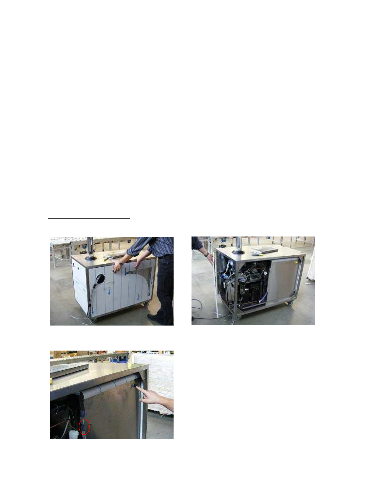
INSTALLATION PROCEDURE
Commissioning
Dismantle the unit, to get access to the cooling system and the electric devices.
Fill the water bath with water, until the level
has reached the pointed height of the water
gauge.
Energize the cooling device and allow the
system to build up an ice bank.
At least 4-5 hours!
Activate the pint portion. Check correct operation and ensure the product pipes are fully primed.
Check portions are correct using a marked container.
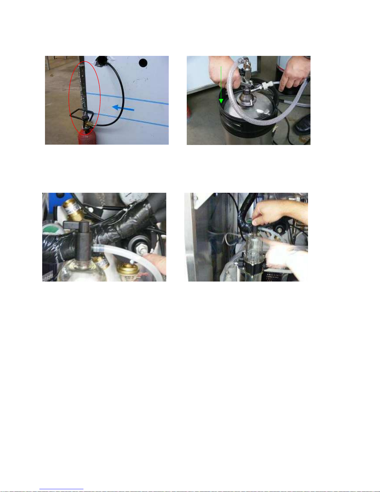
Commissioning UltraFlow font (see Operation)
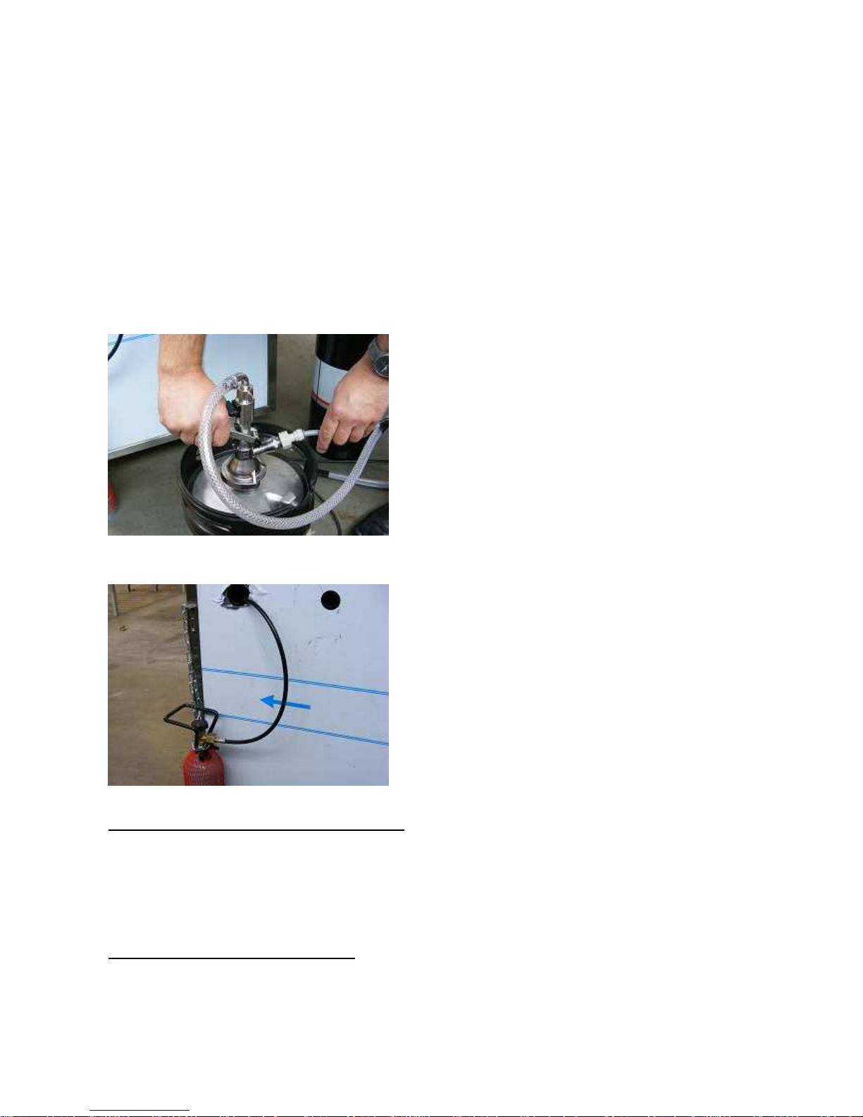
Slide the gas connection through the cut out of
the sheet metal part and mount the casing
again. Connect the gas tank to the unit.
WARNING: Secure the gas tank with the chain
to ensure the tank can not fall down.
Connect the keg connection as shown with a
cleaning tank and clean the complete system
as described in “Sanitizing Product Coils”.
Afterwards connect product tank to the keg
connection.
Turn on the CO2 bottle and set the pressure
gauge to the required equilibrium pressure
+5 psi
Turn the switch at the beer monitor to release
the gathered foam into the overflow.
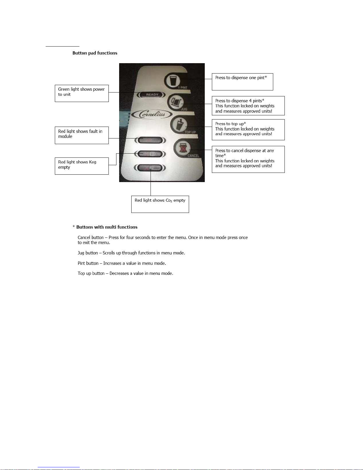
OPERATION
Programming
Normal display will read “Ready”
Press and hold “Cancel” button (red lights will alternate on Keg and gas empty)
Display will show pint and jugs dispensed. (these readings cannot be altered).
Press “Portion 2” button to scroll trough the menu:
Press “Portion 2” display will read “pint set up”
Press “Portion 2” display will read “Jug set up”
Use the “Portion 1” and “Top up” buttons to alter value (this applies to all settings)
Press “Portion 2” display will read “Hit (ms)” 100 – Do not alter this value
Press “Portion 2” display will read “Hold (%) 020 – Do not alter this value
Press “Portion 2” display will read “Pint Timeout” – Do not alter this value
Press “Portion 2” display will read “Jug timeout” 40.0 – Do not alter this value
Press “Portion 2” display will read “Drain Time” 03.0 – Do not alter this value
Press “Portion 2” display will read “Drain delay” 100 - Do not alter this value
Press “Portion 2” display will read “Beer saver” 3500 - Do not alter this value
Press “Portion 2” display will read “Top up valves 2. Alter between 1 valve or two valves. 1 is
for foam, 2 is for clear beer.
To exit the program press “Cancel”
If settings are lost or forgotten, press and hold “Cancel”, whilst holding “Cancel” press
“Portion 2” button and hold for approx 5 seconds. The unit will default to factory settings.
Cleaning mode:
To set cleaning mode press and hold “cancel”, whilst holding “cancel” press “Portion 1”
button, hold both buttons for 5 seconds. This will open the solenoids for approximately 20
minutes to allow fluid to
free flow. To stop cleaning press the “Cancel” button.
Glass activated dispense:
If the glass activated dispense button is used, it must be held on for ½ a second before
dispense will start. This is to prevent the possibility of “nuisance” tripping of the system, for
example, when cleaning the font.
Keg change
Slide the keg connection on the tank and push the
lever down.
It is not possible to push the lever down if it is not
slided on the tank correctly.
To remove keg, simply pull lever up, and slide it back.
CO2 /Mixed Gas Change
To change the CO2 tank, remove the connection and
the chain, place new tank, add the chain again before
connecting the tank to the unit.
SERVICE INFORMATION (FAULT / REPAIRS)
− There are NO ‘user’ (OPERATOR) serviceable items inside the unit
− Maintenance must only be undertaken by a qualified and trained person
− Only replace the fuse protecting the circuit to the unit with one of an identical type and rating
− Isolate the power supply to the unit during maintenance operations
− Only use Cornelius parts for cooler maintenance. Failure to do so will invalidate approvals and
warranty
PREVENTATIVE USER MAINTENANCE
For all of the below, once the maintenance is carried out, follow the Installation
instructions for re commissioning the unit
− Switch off and unplug the unit during user maintenance operations

− In the event of the unit malfunctions or suffers spillage or physical damage, unplug the unit
from its electrical supply
− Do not switch the unit ‘off’ and ‘on’ within five minutes
Sanitizing Product Coils
− Under no circumstances should boiling water or steam be used with this unit as it may result in
permanent damage. The maximum temperature permissible is 40°c
− Sanitize when taste is tainted or periodically as advised by the beverage supplier.
− Cleaning process
The system will require thoroughly cleaning using a recognized beer line cleaner followed by
sufficient clean water to neutralize the system.
Employ the standard procedure when cleaning the system i.e. allow the beer line cleaner to
remain in the system for approximately 15 to 20 minutes drawing fresh cleaner through the
system by operating the pint portion button at approximately 5 minute intervals during the 20
minute soak then thoroughly rinse with clean water using the jug portion button The system
can now be connected to a product keg and primed ready for use.
PLEASE NOTE: When the CO2 supply becomes exhausted the CO2 cut out switch is set to
operate before the line pressure falls below product equilibrium. This will help to ensure that
CO2 breakout is kept to an absolute minimum. Once the CO2 supply is reinstated the font will
automatically resume normal operation. If the product keg empties the system will allow
completion of the last portion before stopping normal dispense operation. Normal operation
will automatically resume when new a product keg is connected to the system.
Cleaning
− Clean parts coming into contact with air and beverage, the mouth of the tap for example, on a
daily basis
− The external faces of the unit should only be wiped down with a damp cloth. Any cleaning
materials should be non-abrasive. Do not use any chemicals to clean.
- The condenser fins must be cleaned at regular intervals (approx. Every 3 months). This is best
done with a brush and vacuum cleaner.
Periodic Testing
The 1989 Electricity at Work Regulations require periodic testing of electrical equipment and this
should only be carried out by a competent person
Daily Inspection
− Check the beverage line for leaks. Only a visual inspection is possible. If liquid escapes, call a
service technician.
− Check the CO2-line for leaks by closing the cylinder globe valve on the CO2-cylinder. The inlet
pressure indicated on the pressure regulator should not drop. If it does, call a service technician
immediately (upon successfully passing this test do not forget to re-open the cylinder valve
afterwards)
Putting out of Service
Perform the following steps in case of protracted periods without use
− Have the device emptied and cleaned. Only trained specialists are to carry out this procedure
− Close the CO2-cylinder (valve on top)
− Pull the mains plug out of socket
− Detach the couplings from beverage containers & CO2 cylinder.
− Pull the UltraFlow tower out of the socket and lay it down on the top of the mobile bar and fix
it.
 Loading...