

Cornelius UCR 700 Series, UCR700-A, UCR700-W Installation & Service Manual
UCR 700 SERIES CONTINUOUS FLOW
ICEMAKER
Installation/Service Manual
Release Date: May, 2001
Publication Number: 630460154
Revision Date: January 12, 2012
Revision: C
Visit the IMI Cornelius web site at www.cornelius.com
for all your Literature needs.

The products, technical information, and instructions contained in this manual are subject to change without notice.
These instructions are not intended to cover all details or variations of the equipment, nor to provide for every possi
ble contingency in the installation, operation or maintenance of this equipment. This manual assumes that the person(s) working on the equipment have been trained and are skilled in working with electrical, plumbing, pneumatic,
and mechanical equipment. It is assumed that appropriate safety precautions are taken and that all local safety and
construction requirements are being met, in addition to the information contained in this manual.
This Product is warranted only as provided in Cornelius’ Commercial Warrant applicable to this Product and is subject to all of the restrictions and limitations contained in the Commercial Warranty.
Cornelius will not be responsible for any repair, replacement or other service required by or loss or damage resulting
from any of the following occurrences, including but not limited to, (1) other than normal and proper use and normal
service conditions with respect to the Product, (2) improper voltage, (3) inadequate wiring, (4) abuse, (5) accident,
(6) alteration, (7) misuse, (8) neglect, (9) unauthorized repair or the failure to utilize suitably qualified and trained per
sons to perform service and/or repair of the Product, (10) improper cleaning, (11) failure to follow installation, operating, cleaning or maintenance instructions, (12) use of “non-authorized” parts (i.e., parts that are not 100%
compatible with the Product) which use voids the entire warranty, (13) Product parts in contact with water or the
product dispensed which are adversely impacted by changes in liquid scale or chemical composition.
Contact Information:
To inquire about current revisions of this and other documentation or for assistance with any Cornelius product contact:
www.cornelius.com
800-238-3600
-
-
Trademarks and Copyrights:
This document contains proprietary information and it may not be reproduced in any way without permission from
Cornelius.
Printed in U.S.A.

TABLE OF CONTENTS
Safety Instructions. . . . . . . . . . . . . . . . . . . . . . . . . . . . . . . . . . . . . . . . . . . . . . . . . . . . . . . . . . . . . . . . 1
Read and Follow ALL Safety Instructions . . . . . . . . . . . . . . . . . . . . . . . . . . . . . . . . . . . . . . . . . . . . 1
Safety Overview . . . . . . . . . . . . . . . . . . . . . . . . . . . . . . . . . . . . . . . . . . . . . . . . . . . . . . . . . . . . 1
Recognition . . . . . . . . . . . . . . . . . . . . . . . . . . . . . . . . . . . . . . . . . . . . . . . . . . . . . . . . . . . . . . . . 1
Different Types of Alerts . . . . . . . . . . . . . . . . . . . . . . . . . . . . . . . . . . . . . . . . . . . . . . . . . . . . . . . . . 1
Safety Tips . . . . . . . . . . . . . . . . . . . . . . . . . . . . . . . . . . . . . . . . . . . . . . . . . . . . . . . . . . . . . . . . . . . 1
Qualified Service Personnel . . . . . . . . . . . . . . . . . . . . . . . . . . . . . . . . . . . . . . . . . . . . . . . . . . . . . . 1
Safety Precautions . . . . . . . . . . . . . . . . . . . . . . . . . . . . . . . . . . . . . . . . . . . . . . . . . . . . . . . . . . . . . 2
Shipping and Storage . . . . . . . . . . . . . . . . . . . . . . . . . . . . . . . . . . . . . . . . . . . . . . . . . . . . . . . . . . . 2
General Description . . . . . . . . . . . . . . . . . . . . . . . . . . . . . . . . . . . . . . . . . . . . . . . . . . . . . . . . . . . . . . 3
To the User of this Manual . . . . . . . . . . . . . . . . . . . . . . . . . . . . . . . . . . . . . . . . . . . . . . . . . . . . . . . 3
Description . . . . . . . . . . . . . . . . . . . . . . . . . . . . . . . . . . . . . . . . . . . . . . . . . . . . . . . . . . . . . . . . . . . 3
Claims Instructions . . . . . . . . . . . . . . . . . . . . . . . . . . . . . . . . . . . . . . . . . . . . . . . . . . . . . . . . . . . . . 3
Warranty reference Information . . . . . . . . . . . . . . . . . . . . . . . . . . . . . . . . . . . . . . . . . . . . . . . . . . . 3
Design Data . . . . . . . . . . . . . . . . . . . . . . . . . . . . . . . . . . . . . . . . . . . . . . . . . . . . . . . . . . . . . . . . . . 3
Specification Chart . . . . . . . . . . . . . . . . . . . . . . . . . . . . . . . . . . . . . . . . . . . . . . . . . . . . . . . . . . . . . 4
Installation . . . . . . . . . . . . . . . . . . . . . . . . . . . . . . . . . . . . . . . . . . . . . . . . . . . . . . . . . . . . . . . . . . . . . . 6
Pre-Installation . . . . . . . . . . . . . . . . . . . . . . . . . . . . . . . . . . . . . . . . . . . . . . . . . . . . . . . . . . . . . . . . 6
Freight Damage Claim . . . . . . . . . . . . . . . . . . . . . . . . . . . . . . . . . . . . . . . . . . . . . . . . . . . . . . . 6
Counter . . . . . . . . . . . . . . . . . . . . . . . . . . . . . . . . . . . . . . . . . . . . . . . . . . . . . . . . . . . . . . . . . . . 6
Electrical . . . . . . . . . . . . . . . . . . . . . . . . . . . . . . . . . . . . . . . . . . . . . . . . . . . . . . . . . . . . . . . . . . 6
Drain . . . . . . . . . . . . . . . . . . . . . . . . . . . . . . . . . . . . . . . . . . . . . . . . . . . . . . . . . . . . . . . . . . . . . 6
Installation . . . . . . . . . . . . . . . . . . . . . . . . . . . . . . . . . . . . . . . . . . . . . . . . . . . . . . . . . . . . . . . . . . . . 6
Initial Start up, Checks and Adjustment Instructions . . . . . . . . . . . . . . . . . . . . . . . . . . . . . . . . . . . . 8
Guide to service . . . . . . . . . . . . . . . . . . . . . . . . . . . . . . . . . . . . . . . . . . . . . . . . . . . . . . . . . . . . . . . . . 9
Icemaker Cleaning and Sanitizing Procedures . . . . . . . . . . . . . . . . . . . . . . . . . . . . . . . . . . . . . . . . 9
Maintenance . . . . . . . . . . . . . . . . . . . . . . . . . . . . . . . . . . . . . . . . . . . . . . . . . . . . . . . . . . . . . . . . . . 9
Monthly . . . . . . . . . . . . . . . . . . . . . . . . . . . . . . . . . . . . . . . . . . . . . . . . . . . . . . . . . . . . . . . . . . . 9
Quarterly . . . . . . . . . . . . . . . . . . . . . . . . . . . . . . . . . . . . . . . . . . . . . . . . . . . . . . . . . . . . . . . . . . 9
Semi-Annually . . . . . . . . . . . . . . . . . . . . . . . . . . . . . . . . . . . . . . . . . . . . . . . . . . . . . . . . . . . . . 10
Water Level Control . . . . . . . . . . . . . . . . . . . . . . . . . . . . . . . . . . . . . . . . . . . . . . . . . . . . . . . . . . . 10
How Water Level Control Works . . . . . . . . . . . . . . . . . . . . . . . . . . . . . . . . . . . . . . . . . . . . . . . 10
Purpose . . . . . . . . . . . . . . . . . . . . . . . . . . . . . . . . . . . . . . . . . . . . . . . . . . . . . . . . . . . . . . . . . . 10
To Replace Water Level Control . . . . . . . . . . . . . . . . . . . . . . . . . . . . . . . . . . . . . . . . . . . . . . . 11
To Replace Water Level Safety Switch . . . . . . . . . . . . . . . . . . . . . . . . . . . . . . . . . . . . . . . . . . 11
Refrigeration System . . . . . . . . . . . . . . . . . . . . . . . . . . . . . . . . . . . . . . . . . . . . . . . . . . . . . . . . . . 11
Refrigeration System Adjustments . . . . . . . . . . . . . . . . . . . . . . . . . . . . . . . . . . . . . . . . . . . . . . . . 11
Expansion Valve . . . . . . . . . . . . . . . . . . . . . . . . . . . . . . . . . . . . . . . . . . . . . . . . . . . . . . . . . . . . . . 12
Adjustment and Troubleshooting . . . . . . . . . . . . . . . . . . . . . . . . . . . . . . . . . . . . . . . . . . . . . . . . . 12

Condenser Modulating Valve . . . . . . . . . . . . . . . . . . . . . . . . . . . . . . . . . . . . . . . . . . . . . . . . . . . . 12
Condenser Modulating Valve Removal . . . . . . . . . . . . . . . . . . . . . . . . . . . . . . . . . . . . . . . . . . . . . 13
Bin Control . . . . . . . . . . . . . . . . . . . . . . . . . . . . . . . . . . . . . . . . . . . . . . . . . . . . . . . . . . . . . . . . . . 13
Gearmotor . . . . . . . . . . . . . . . . . . . . . . . . . . . . . . . . . . . . . . . . . . . . . . . . . . . . . . . . . . . . . . . . . . . 14
Motor Check . . . . . . . . . . . . . . . . . . . . . . . . . . . . . . . . . . . . . . . . . . . . . . . . . . . . . . . . . . . . . . . . . 15
Start Relay . . . . . . . . . . . . . . . . . . . . . . . . . . . . . . . . . . . . . . . . . . . . . . . . . . . . . . . . . . . . . . . . . . 15
To Replace Gearmotor Assembly . . . . . . . . . . . . . . . . . . . . . . . . . . . . . . . . . . . . . . . . . . . . . . 15
Auger and Extruding Head Removal . . . . . . . . . . . . . . . . . . . . . . . . . . . . . . . . . . . . . . . . . . . . . . 16
Installation and Shaft Seal Replacement . . . . . . . . . . . . . . . . . . . . . . . . . . . . . . . . . . . . . . . . . . . 16
Upper Nut and Bearing Assembly . . . . . . . . . . . . . . . . . . . . . . . . . . . . . . . . . . . . . . . . . . . . . . . . . 16
To Replace Bearing . . . . . . . . . . . . . . . . . . . . . . . . . . . . . . . . . . . . . . . . . . . . . . . . . . . . . . . . 17
Electrical Checkout . . . . . . . . . . . . . . . . . . . . . . . . . . . . . . . . . . . . . . . . . . . . . . . . . . . . . . . . . . . . 17
Overload Check . . . . . . . . . . . . . . . . . . . . . . . . . . . . . . . . . . . . . . . . . . . . . . . . . . . . . . . . . . . . . . . 17
Compressor Check . . . . . . . . . . . . . . . . . . . . . . . . . . . . . . . . . . . . . . . . . . . . . . . . . . . . . . . . . . . . 17
Capacitor Check . . . . . . . . . . . . . . . . . . . . . . . . . . . . . . . . . . . . . . . . . . . . . . . . . . . . . . . . . . . . . . 18
Safety Controls . . . . . . . . . . . . . . . . . . . . . . . . . . . . . . . . . . . . . . . . . . . . . . . . . . . . . . . . . . . . . . . 18
Troubleshooting . . . . . . . . . . . . . . . . . . . . . . . . . . . . . . . . . . . . . . . . . . . . . . . . . . . . . . . . . . . . . . . . 23
Troubleshooting Compressors . . . . . . . . . . . . . . . . . . . . . . . . . . . . . . . . . . . . . . . . . . . . . 23
Parts List . . . . . . . . . . . . . . . . . . . . . . . . . . . . . . . . . . . . . . . . . . . . . . . . . . . . . . . . . . . . . . . . . . . . . . 24
UCR 700 Series Continuous Flow Icemaker Installation/ServiceManual
!
WAR NING:
CAUTION:
!
!
WAR NING:
!
SAFETY INSTRUCTIONS
READ AND FOLLOW ALL SAFETY INSTRUCTIONS
Safety Overview
• Read and follow ALL SAFETY INSTRUCTIONS in this manual and any warning/caution labels on the unit (decals, labels or
laminated cards).
• Read and understand ALL applicable OSHA (Occupational Safety and Health Administration) safety regulations before
operating this unit.
Recognition
Recognize Safety Alerts
This is the safety alert symbol. When you see it in this manual or on the unit,
be alert to the potential of personal injury or damage to the unit.
DIFFERENT TYPES OF ALERTS
Indicates an immediate hazardous situation which if not avoided WILL result in serious injury, death or equipment
damage.
Indicates a potentially hazardous situation which, if not avoided, COULD result in serious injury, death, or equipment
damage.
Indicates a potentially hazardous situation which, if not avoided, MAY result in minor or moderate injury or equipment
damage.
SAFETY TIPS
• Carefully read and follow all safety messages in this manual and safety signs on the unit.
• Keep safety signs in good condition and replace missing or damaged items.
• Learn how to operate the unit and how to use the controls properly.
• Do not let anyone operate the unit without proper training. This appliance is not intended for use by very young children or
infirm persons without supervision. Young children should be supervised to ensure that they do not play with the appliance.
• Keep your unit in proper working condition and do not allow unauthorized modifications to the unit.
QUALIFIED SERVICE PERSONNEL
Only trained and certified electrical, plumbing and refrigeration technicians should service this unit. ALL WIRING AND
PLUMBING MUST CONFORM TO NATIONAL AND LOCAL CODES. FAILURE TO COMPLY COULD RESULT IN
SERIOUS INJURY, DEATH OR EQUIPMENT DAMAGE.
Publication Number: 630460154 - 1 - © 2001-2012, IMI Cornelius Inc.
UCR 700 Series Continuous Flow Icemaker Installation/Service Manual
!
WAR NING:
CAUTION:
!
CAUTION:
!
SAFETY PRECAUTIONS
This unit has been specifically designed to provide protection against personal injury. To ensure continued protection
observe the following:
Disconnect power to the unit before servicing following all lock out/tag out procedures established by the user. Verify
all of the power is off to the unit before any work is performed.
Failure to disconnect the power could result in serious injury, death or equipment damage.
Always be sure to keep area around the unit clean and free of clutter. Failure to keep this area clean may result in
injury or equipment damage.
SHIPPING AND STORAGE
Before shipping, storing, or relocating the unit, the unit must be sanitized and all sanitizing solution must be drained
from the system. A freezing ambient environment will cause residual sanitizing solution or water remaining inside the
unit to freeze resulting in damage to internal components.
© 2001-2012, IMI Cornelius Inc. - 2 - Publication Number: 630460154
UCR 700 Series Continuous Flow Icemaker Installation/ServiceManual
GENERAL DESCRIPTION
TO THE USER OF THIS MANUAL
This manual covers the installation and assembly of the Air--Cooled or Water--Cooled Model UC700 Icemaker with
the Model UC150 Dispenser. Refer to Table of Contents for page location of detailed information pertaining to
questions that may arise during installation or operation of this equipment.
DESCRIPTION
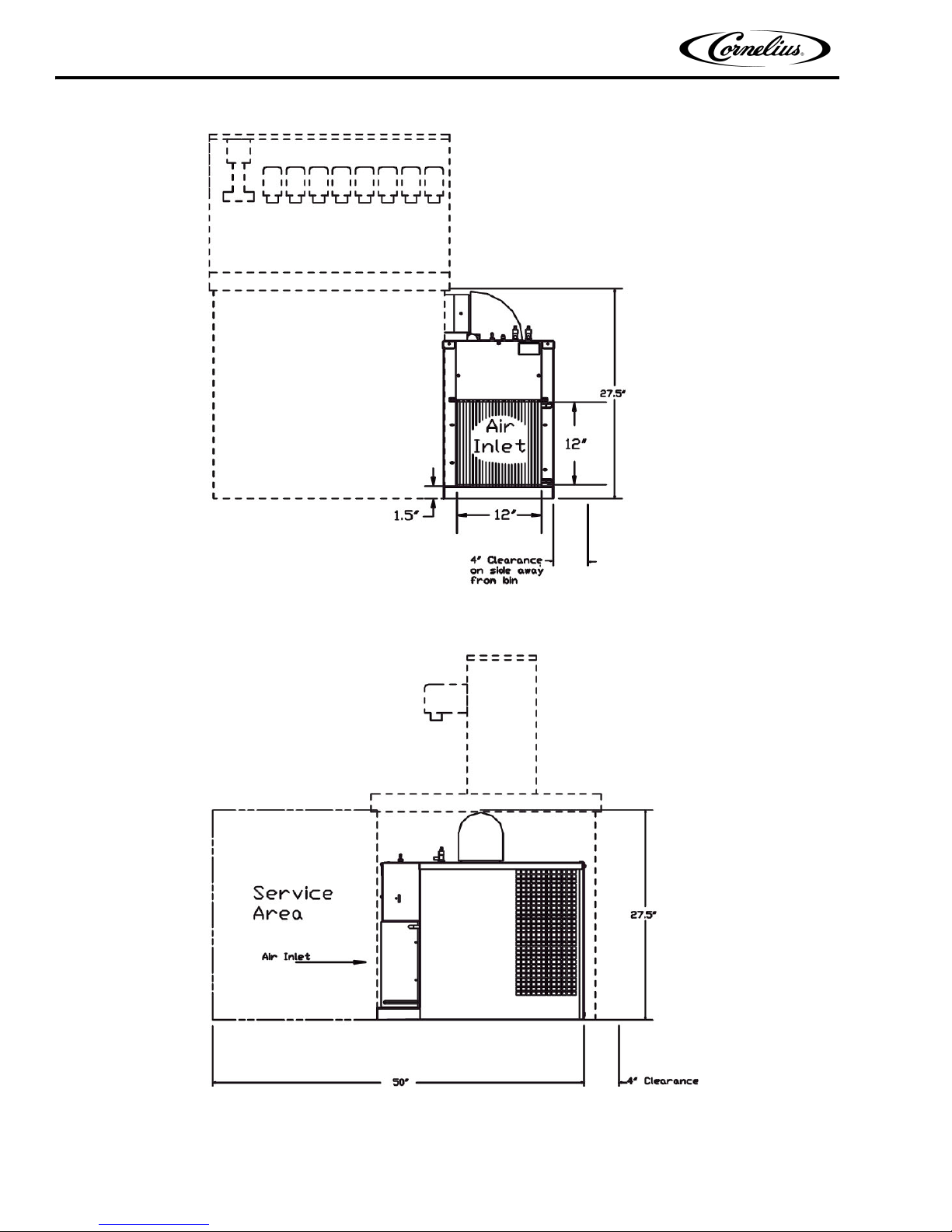
The UC700 is a chuncklet Icemaker designed to be installed under a counter adjacent to an Ice Dispenser or an Ice
Storage Bin. The Icemaker will deliver ice to either the left or right side. The Icemaker requires a 12--inch by 12-inch opening at the lower front of the Unit for air intake. A minimum of 1.5 sq. ft. opening must be provided out the
left or right side and the rear of the machine for air exaust.
CLAIMS INSTRUCTIONS
Claims: In the event of shortage, notify the carrier as well as IMI Cornelius immediately. In the event of damage,
notify the carrier. IMI Cornelius is not responsible for damage occurring in transit, but will gladly render assistance
necessary to pursue your claim. Merchandise must be inspected for concealed damage within 15 days of receipt.
WARRANTY REFERENCE INFORMATION
Warranty Registration Date
(to be filled out by customer)
Unit Part Number:
Serial Number:
Install Date:
Local Authorized Service Center:
DESIGN DATA
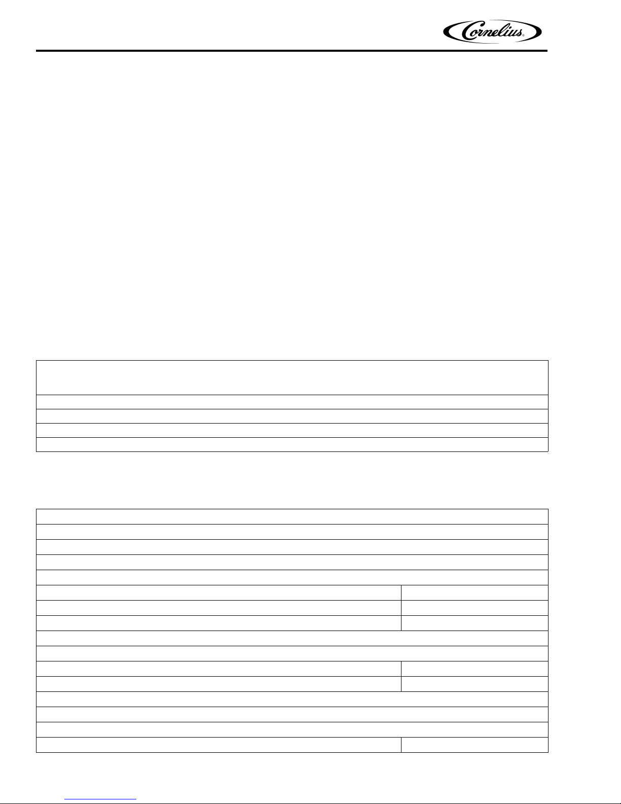
Table 1. Design Date
Unit Model Number
UCR700--A Series Continuous--Flow Icemaker (Air--Cooled)
UCR700--W Series Continuous--Flow Icemaker (Water--Cooled)
Unit Overall Dimensions:
Height 27 inchs
Width 15.7 inchs
Depth 25.5 inchs
:
Clearances Dimensions Required:
Front Side Service Access (Removable front panel to allo
Side Opposite Storage Bin for Air Exaust 4 inchs
Rear for Air Exaust
Weights:
Shipping Weight 184 pounds
Publication Number: 630460154 - 3 - © 2001-2012, IMI Cornelius Inc.
w removal of Unit) 25 inches
UCR 700 Series Continuous Flow Icemaker Installation/Service Manual
Table 1. Design Date
Unit Model Number:
Water Supply--Water inlet fitting is 1/4--inch SAE flare located at the top front of the Unit. The Unit is designed to
operate on water pressure between 10 PSI and 90 PSI.
Drain Overflow Line (Located at rear of the Unit) 3/8--inch Flexible Tubing
Ambient Operating Temperature 40° F to 100° F
Electrical:
Unit Electrical Rating
115 VAC, 60 Hz, 15.6 Amps,
Sing
le Phase
115 VAC, 60 hz, 20 Amps
Recommended Electrical Supply
Dedica
ted 3--Wire Grounded
Circuit
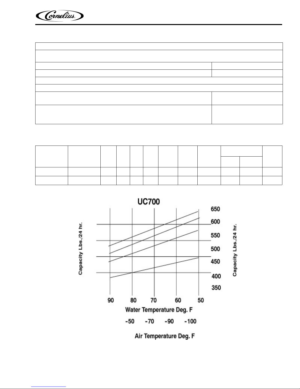
SPECIFICATION CHART
Models
UCR700--A Air Cooled 115 60 1 2 12 1.6 2 24 R404A 20
UCR700--W Water Cooled 115 60 1 2 12 N/A 2 13 R404A 20
Condensing
Unit
VAC HZ PH Wir e
Comp.
RLA
Fan
Amps
GRMTR
Amps
Refrigerant
Oz. Type
Circuit
Fuse
© 2001-2012, IMI Cornelius Inc. - 4 - Publication Number: 630460154
UCR 700 Series Continuous Flow Icemaker Installation/ServiceManual
Publication Number: 630460154 - 5 - © 2001-2012, IMI Cornelius Inc.
Figure 1. Clearance Requirements

UCR 700 Series Continuous Flow Icemaker Installation/Service Manual
INSTALLATION
PRE-INSTALLATION
FREIGHT DAMAGE CLAIM
The delivery of your equipment (Frieght Company, Distributor, or dealer) is responsible for loss or damage of your
shipment. All claims must be filed with the deliverer of your equipment. Please follow the steps below to determine
if your shipment is satisfactory or if a claim must be filed:
1. Check the number of products delivered against the number of products listed on the delivery receipt.
Should the totals not match, have the driver note all errors on both copies and both you and the driver sign
and date said notation.
2. Inspect all cartons for visible damage. Open and inspect as required before the driver leaves and have him
or her note any damage on the receipts. All damaged claims must be inspected within 15 days of delivery.
Notify your carrier immediately if concealed damage is found after delivery.
3. Should concealed damage be found when the product is unpacked, retain the packing material and the
product and request an inspection from the deliverer.
4. All claims for loss or damage should be filed at once. Delays in filing will reduce the chance of achieving a
satisfactory resolution to the claim.
COUNTER
1. A flat and level counter space sufficiently strong to support the weight of the Dispenser and the Icemaker.
The Icemaker may be installed on the left or the right side of the Dispenser.
2. General Requirements:
A. The front of the Icemaker must be free of obstructions.
B. Allow a 4--inch minimum clearance between exaust side of the Icemaker and adjacent equipment.
C. A louvered front panel (12--inches X 12--inches) aligned with the air inlet of the Icemaker and adequate
ventilation (1.5 Sq. feet opening) in the counter for exaust air.
D. A removable panel in the counter face (from 2--inches below the top of the counter to the floor, a mini-
mum of 19--inches wide) to allow removal of the Icemaker.
ELECTRICAL
Two separate 20 amp, 120VAC, 60 Hz electrical circuits.
DRAIN
One drain beneath the counter at floor level which will accomodate both the drain from the Icemaker and the
Dispenser.
INSTALLATION
1. Keep unit in the upright position, remove carton and pallet from the Icemaker and inspect for damage. If
any damage is found, file a claim with carrier immediately.
2. Locate startup card either on outside of container or on plastic liner. Fill in proper information and send one
to factory, and other copy to distributor. Postage is prepaid.
3. Install the Dispenser first, following installation instructions supplied with the Dispenser.
4. Remove the two hole plugs from the side of the dispenser.
© 2001-2012, IMI Cornelius Inc. - 6 - Publication Number: 630460154
UCR 700 Series Continuous Flow Icemaker Installation/ServiceManual
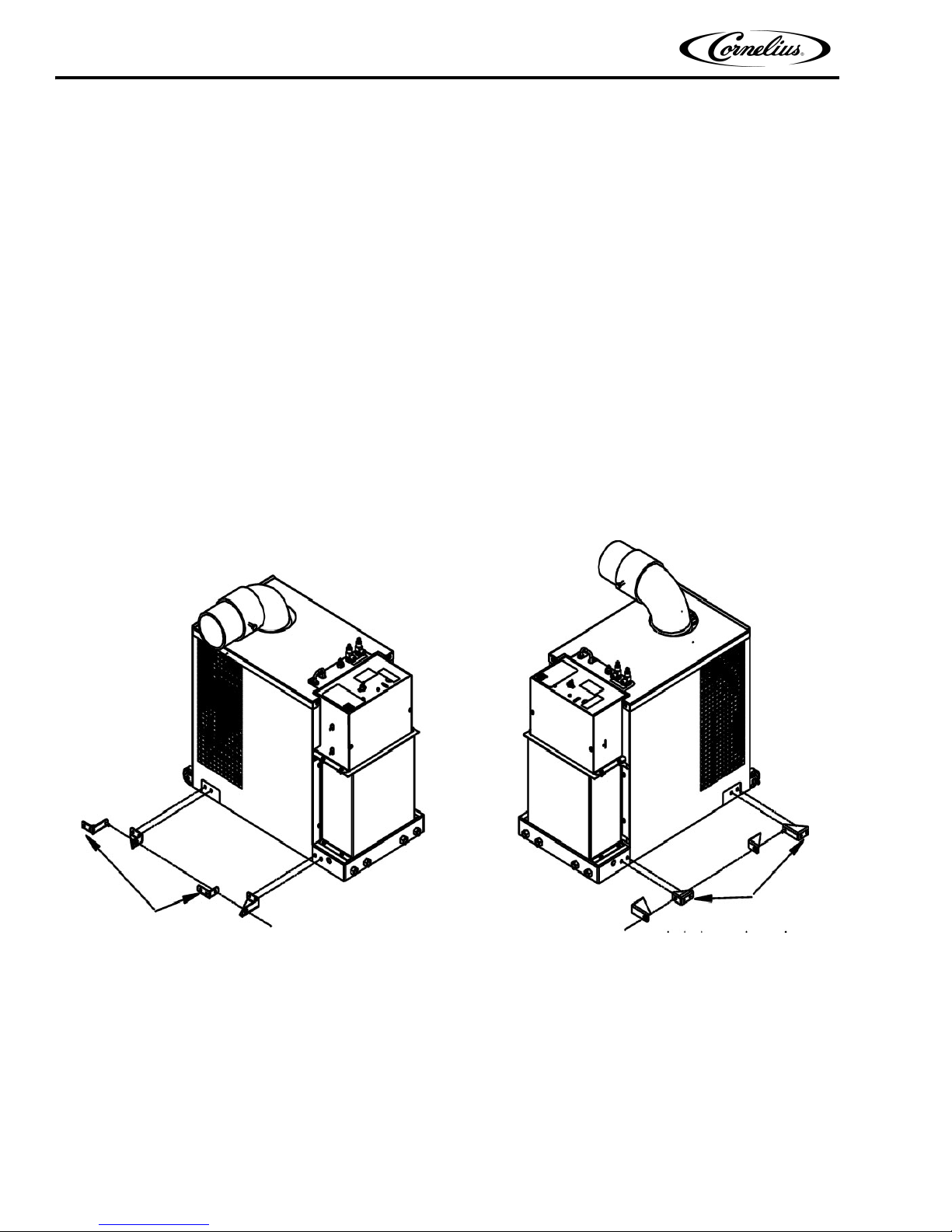
Attachtobin
RightSideInstall
Attachtobin
LeftSideInstall
A. The plugs are pressed in and sealed with a silastic sealant. To remove pry the outside cap off and then
press the inside plug into the bin. Discard both plugs.
B. Install the icemaker alignment brackets (Supplied with icemaker) to the dispenser (See Figure 2).
5. Install the Icemaker:
A. Install the icemaker alignment brackets (Supplied with icemaker) to the icemaker (See Figure 2).
B. Roll the Icemaker into the cabinet alongside the Dispenser.
C. Level and align the icemaker to the dispenser using the four level adjustment bolts located on the lower
front of the Icemaker.
D. Install the locking bolt on the lower front of the icemaker.
E. Connect drain, power and water.
6. Install transport tube:
A. Insert the ice transport tube through the bin into the transport elbow on the Icemaker. (Note: The ice-
maker is equipped with a safety switch located at the base of the elbow, this switch will prevent the icemaker from running if the elbow is not properly installed).
B. Align the nylon lock screw on the elbow with the recess on the tube. Install lock screw.
7. Connect bin thermostat:
A. Locate bin thermostat cable supplied with the icemaker (Black cable) and connect to electrical box on
the UCR700 and the receptacle on the side of the dispenser.
Publication Number: 630460154 - 7 - © 2001-2012, IMI Cornelius Inc.
Figure 2. Side Bracket Installation
 Loading...