

Page 1
Super Seal Replacement Kit Installation Manual
!
WARNING:
.
.
INSTALLATION INSTRUCTIONS
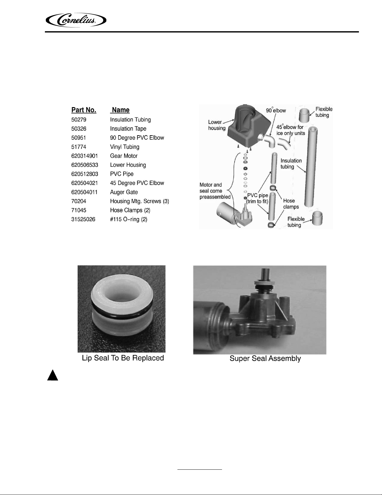
SUPER SEAL REPLACEMENT KIT P/N 629087456
Applies to both the UC150 Ice Only and the IU150 BC
NOTE: This kit will obsolete Shaft Seal P/N 620701121 and Auger Motor P/N 620305201. This kit is
intended for replacement of obsolete lip seal. This kit requires removal of existing lower housing, seal, and auger motor.
Disconnect power to the unit before servicing. Follow all lock out/tag out procedures established by the user. Verify all
power is off to the unit before performing any work.
Failure to comply could result in serious injury, death or damage to the equipment.
Revised: August 3, 2010 www.cornelius.com
© 2002-2010, IMI Cornelius Inc. - 1 - Publication Number: 620919536
Rev: D
Page 2
Super Seal Replacement Kit Installation Manual
Cut
Drain
Here
Remove
Lower
Housing
INSTRUCTIONS
This kit requires that the lower housing be replaced due to incompatibility of the existing housing with the new motor
and super seal design. To remove the lower housing, first remove the top cover over the ice chute. Then pry retainer
off ice chute to allow removal of ice chute. This will expose the top of the auger, which can now be removed by lifting it
upward. The last items to be removed are the two auger housing halves. Once again you can lift these upward.
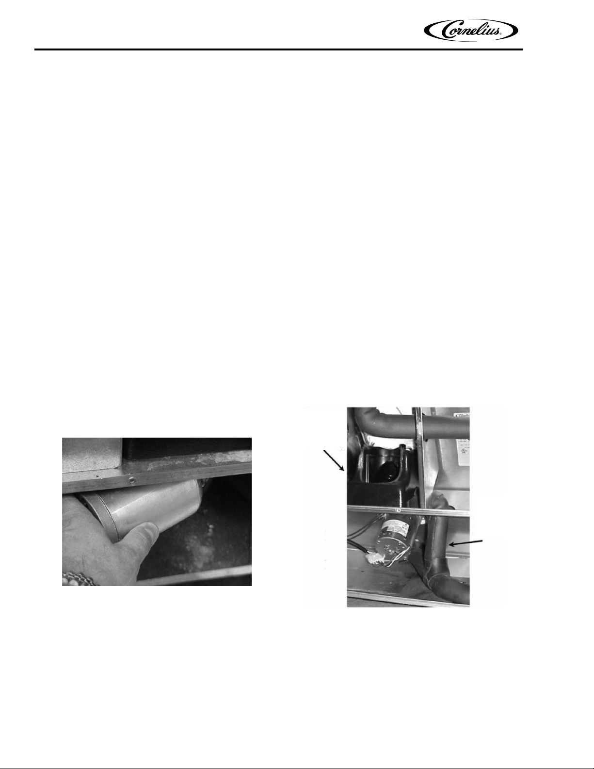
Before you can get to the three screws that retain the lower housing, you must remove the auger motor. Turn the
auger motor counterclockwise approximately a quarter turn and then move downward to remove the motor (See
Figure 1). This motor may now be discarded.
Next, cut the drain line that runs from the back of the lower housing as indicated by the arrow. Pick a point
approximately 4 inches along the vertical section and then cut the drain line (See Figure 2). Underneath the sheet
metal bracket there are three Phillips head screws that need to be removed. You may now remove and discard the
lower housing.
This process for removing the lower housing is the same regardless of the type of dispenser you may have. This
technique will work for both the UC150 Ice Only and IF150 BC. To reassemble the dispenser with the new parts, you
will just reverse the procedure used to remove the parts. Take the time to thread the screws into the bosses on the
bottom of the lower housing and then remove them. This will make re-assembly much easier. Make sure that O-ring
is in place atop the ceramic portion of the seal when putting auger motor into lower housing (See Figure 3).
When installing motor with seal assembly use water as the lubricant. Note that the kit is shipped with 2 (two)
spare o-rings in case you should misplace one.
NOTE: When the seal is installed on the shaft, it should be allowed to rest in its free state. In the free state
the ceramic seat will be butt up to the shaft retainer ring. It should not be compressed to its operating height prior to installation in the lower housing. If you should compress the seal assembly
the O-ring may adhere to the shaft not allowing the seal set to return to its free state. If this should
happen, one must carefully push on the carbon seal moving the seal assembly in a direction
towards the shaft end until the ceramic seat once again rests against the shaft retaining ring.
Figure 1. Figure 2.
Publication Number: 620919536 - 2 - © 2002-2010, IMI Cornelius Inc.
Page 3

Super Seal Replacement Kit Installation Manual
Figure 3. Figure 4.
REPLACEMENT OF THE AUGER GATE
The ice chute is constructed for simple breakdown (tools are not required). First remove the tower cap by removing
the knurled screws. Once the tower cap is out of the way you will see a wire retainer. You will need to pop the retainer
off to remove the ice chute assembly. To remove the wire retainer, place your fingers on the backside of the ice chute
with your thumbs pointing upward. Place your thumbs on the retainer wire and with a slight upward movement push
the wire retainer towards the rear of the unit (See Figure 5). The retainer should pop out of the saddle and swing out
of the way.
At this point, you should be able to pull up on the ice chute and remove it from the assembly. You will notice that the
ice chute is made up of three pieces. That is the ice chute, the ice chute cover, and the auger gate.
To remove the auger gate, place your thumb under the tab on the ice chute cover and press up (See Figure 7). When
reassembling the ice chute, make sure that the gate is sitting in the slots in the ice chute with the short flap side up
(See Figure 8).
Figure 5. Figure 6.
© 2002-2010, IMI Cornelius Inc. - 3 - Publication Number: 620919536
Page 4

Super Seal Replacement Kit Installation Manual
Figure 7. Figure 8.
Publication Number: 620919536 - 4 - © 2002-2010, IMI Cornelius Inc.
 Loading...