

Cornelius TEA URN Service Manual
Service Manual
TEA URN
POST-MIX
BEVERAGE DISPENSER
IMPORTANT:
TO THE INSTALLER.
It is the responsibility of the Installer to
ensure that the water supply to the
dispensing equipment is provided with
protection against backflow by an air gap as
defined in ANSI/ASME A112. 1.2-1979; or an
approved vacuum breaker or other such
method as proved effective by test.
IMI CORNELIUS INC.
One Cornelius Place
Anoka, MN. 55303–6234
Telephone (800) 238–3600
Facsimile (612) 422–3232
Water pipe connections and fixtures directly
connected to a potable water supply shall be
sized, installed, and maintained according to
Federal, State, and Local laws.
Part No. 312020000
December 7, 1993
Revised: July 8, 1994
Control Code A
THIS DOCUMENT CONTAINS IMPORTANT INFORMATION
This Installation Manual must be read and understood before starting to install or operate this equipment.
IMI CORNELIUS INC; 1993-94
Printed in U. S.A.-94

TABLE OF CONTENTS
GENERAL INFORMATION 1. . . . . . . . . . . . . . . . .
GENERAL DESCRIPTION 1. . . . . . . . . . . . . . .
UNIT DESCRIPTION 1. . . . . . . . . . . . . . . . . . . .
DESIGN DATA 1. . . . . . . . . . . . . . . . . . . . . . . . . .
THEORY OF OPERATION 1. . . . . . . . . . . . . . .
INSTALLATION 4. . . . . . . . . . . . . . . . . . . . . . . . . . .
RECEIVING 4. . . . . . . . . . . . . . . . . . . . . . . . . . . .
UNPACKING AND INSPECTION 4. . . . . . . . . .
IDENTIFICATION OF LOOSE-SHIPPED
PARTS 4. . . . . . . . . . . . . . . . . . . . . . . . . . . . . . . .
LOCATION SELECTION 4. . . . . . . . . . . . . . . . .
INSTALLATION 4. . . . . . . . . . . . . . . . . . . . . . . . .
PREPARING UNIT FOR OPERATION 5. . . . .
OPERATORS INSTRUCTIONS 6. . . . . . . . . . . . .
CHECK OR CHANGE NITROGEN
CYLINDER 6. . . . . . . . . . . . . . . . . . . . . . . . . . .
CHANGE CONCENTRATE TANK 6. . . . . . .
SERVICE AND MAINTENANCE 7. . . . . . . . . . . .
APPLICABLE WARNINGS, CAUTIONS AND
NOTES 7. . . . . . . . . . . . . . . . . . . . . . . . . . . . . .
MAINTENANCE SCHEDULE 7. . . . . . . . . . .
CHECK WATER FLOW RATE 7. . . . . . . . . .
CHECK CONCENTRATE-TO-WATER
RATIO 7. . . . . . . . . . . . . . . . . . . . . . . . . . . . . . .
CLEAN DISPENSING VALVES 8. . . . . . . . .
SANITIZING TANK TYPE CONCENTRATE
SYSTEMS 8. . . . . . . . . . . . . . . . . . . . . . . . . . .
SANITIZING BAG-IN-BOX CONCENTRATE
SYSTEMS 9. . . . . . . . . . . . . . . . . . . . . . . . . . .
CLEANING THE NITROGEN GAS CHECK
VALVE 9. . . . . . . . . . . . . . . . . . . . . . . . . . . . . . .
PAGE
PAGE
TROUBLESHOOTING 13. . . . . . . . . . . . . . . . . . . . .
WATER-TO-CONCENTRATE ‘‘RATIO’’ OF DISPENSED PRODUCT TOO LOW OR
TOO HIGH. 13. . . . . . . . . . . . . . . . . . . . . . . . . . . .
ADJUSTMENT OF DISPENSING VALVE CONCENTRATE FLOW REGULATOR DOES NOT
INCREASE WATER-TO-CONCENTRATE ‘‘RA-
TIO’’. 13. . . . . . . . . . . . . . . . . . . . . . . . . . . . . . . . . .
ADJUSTMENT OF DISPENSING VALVE CONCENTRATE FLOW REGULATOR DOES NOT
DECREASE TO DESIRED WATER-TO-CONCEN -
TRATE ‘‘RATIO’’. 13. . . . . . . . . . . . . . . . . . . . . . . .
ONLY WATER DISPENSED. 13. . . . . . . . . . . . .
ONLY CONCENTRATE DISPENSED. 14. . . . .
NO CONCENTRATE OR WATER
DISPENSED. 14. . . . . . . . . . . . . . . . . . . . . . . . . . .
LIST OF FIGURES
FIGURE 1. POST MIX TEA URN 1. . . . . . . . . . . .
FIGURE 2. FLOW DIAGRAM FOR CONCENTRATE
TANK UNIT 2. . . . . . . . . . . . . . . . . . . . . . . . . . . . . . .
FIGURE 3. FLOW DIAGRAM FOR BAG-IN-BOX
CONCENTRATE UNIT 3. . . . . . . . . . . . . . . . . . . . .
FIGURE 4. RATIO CUP AND CONCENTRATE BYPASS ASS’Y (SF-1 SINGLE FLAVOR DISPENSING
VALVE) 8. . . . . . . . . . . . . . . . . . . . . . . . . . . . . . . . . .
FIGURE 5. NITROGEN GAS CHECK VALVE 10.
LIST OF TABLES
TABLE 1. DESIGN DATA 1. . . . . . . . . . . . . . . . .
TABLE 2. LOOSE-SHIPPED PARTS 4. . . . . .
i 312020000
GENERAL INFORMATION
IMPORTANT: To the user of this manual – This
manual is a guide for installing, operating, and
maintaining this equipment. Refer to the Table of
Contents for page location for detailed
information pertaining to questions that arise
during installation, operation, service, or
maintenance of this equipment.
GENERAL DESCRIPTION
This section provides a description, theory of
operation, and design data for the Tea Urn Post-Mix
Beverage Dispenser, hereinafter referred to as a
Unit.
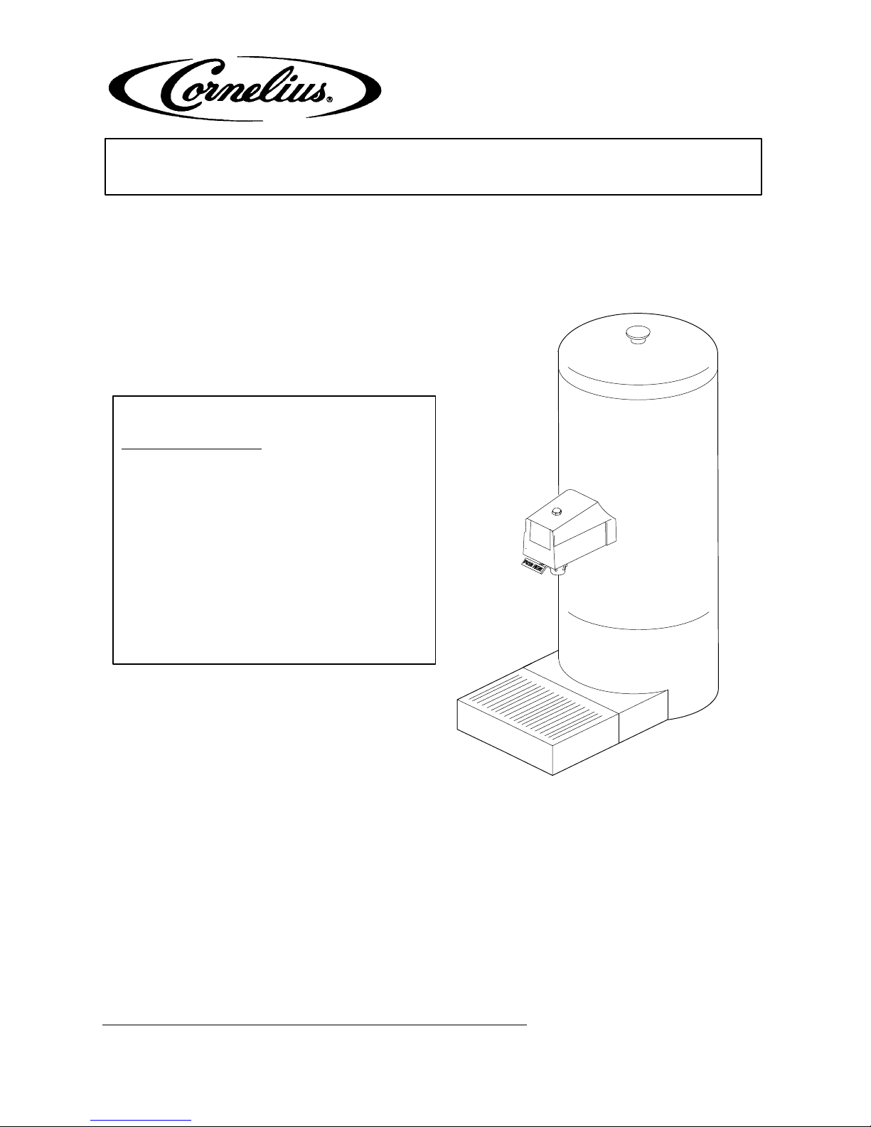
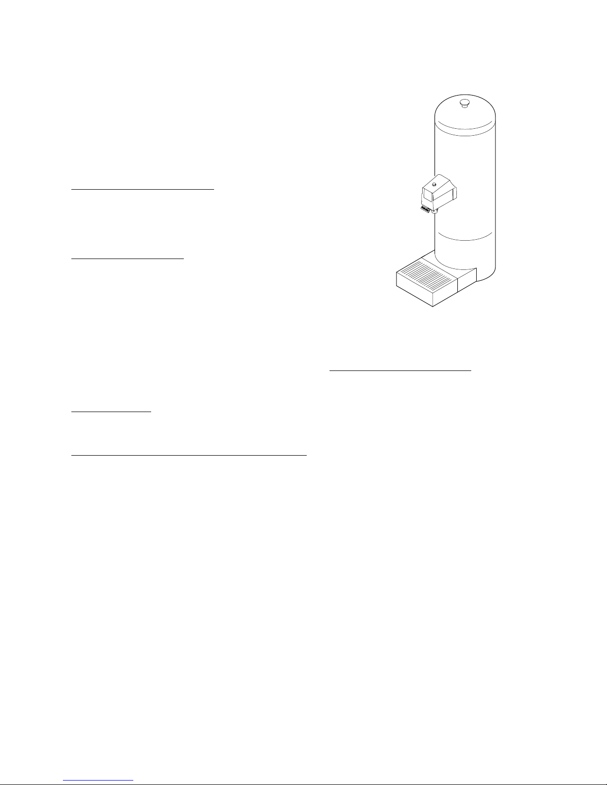
UNIT DESCRIPTION
The Unit (see Figure 1) is compact and intended for
countertop installation. The Unit dispenses
liquid-base concentrate combined with water to
create a finished drink. The Unit is operated by
pressing against a lever arm which extends below
the dispensing valve Cover.
Components are mounted on a stainless steel
enclosure which rests on the countertop. External
connections required are a plain water source and a
source of concentrate.
DESIGN DATA
Design data for all Units is given in Table 1.
Table 1. Design Data
Unit Part Numbers:
Unit with Drip Tray and Cup Rest 416401
Unit without Drip Tray and Cup
Rest
Overall Dimensions (approximate): With Cup Rest &
Drip Tray
Height 25 inches
Width 9 inches
Depth 15 inches
Weights (approximate):
Shipping 11 pounds
Dry Weight 8 pounds
Dispensing Rate (approx.) 1–1/2
Ambient Operating Temperature 40_F to 100_F
416402
ounces/sec
FIGURE 1. POST MIX TEA URN
THEORY OF OPERATION
(see Figure 2)
Note: The gas-operated concentrate pump in the
system, which provides concentrate to the
Dispenser, may be driven by carbon dioxide
(CO2) gas or by compressed air or an electrically
operated pump may be used in place of the
gas-operated pump.
The concentrate is stored in a collapsible bag within
a sturdy box which is called a bag–in–box. When the
dispensing valve is opened, a pump operated by gas
pressure delivers concentrate from the bag-in-box to
the dispensing valve. At the same time, plain water
also enters the dispensing valve. Concentrate and
plain water meet simultaneously at the dispensing
valve resulting in a finished drink being dispensed.
Dispensing continues from the valve as long as the
dispense lever is held down.
The dispensing valve components are accessible by
removing hex nut securing cover to the valve, then
remove cover. The dispensing valve can be removed
from the Unit entirely by releasing two latches.
Concentrate and plain water connections are made
to flared fittings on back side of the Unit.
Operating Pressures:
Water Inlet Supply Line 40 to 125 psig
Components are mounted on a Stainless Steel
Enclosure which may be fastened to the countertop.
The Unit is available with or without a removable Drip
Tray and Cup Rest.
1
312020000
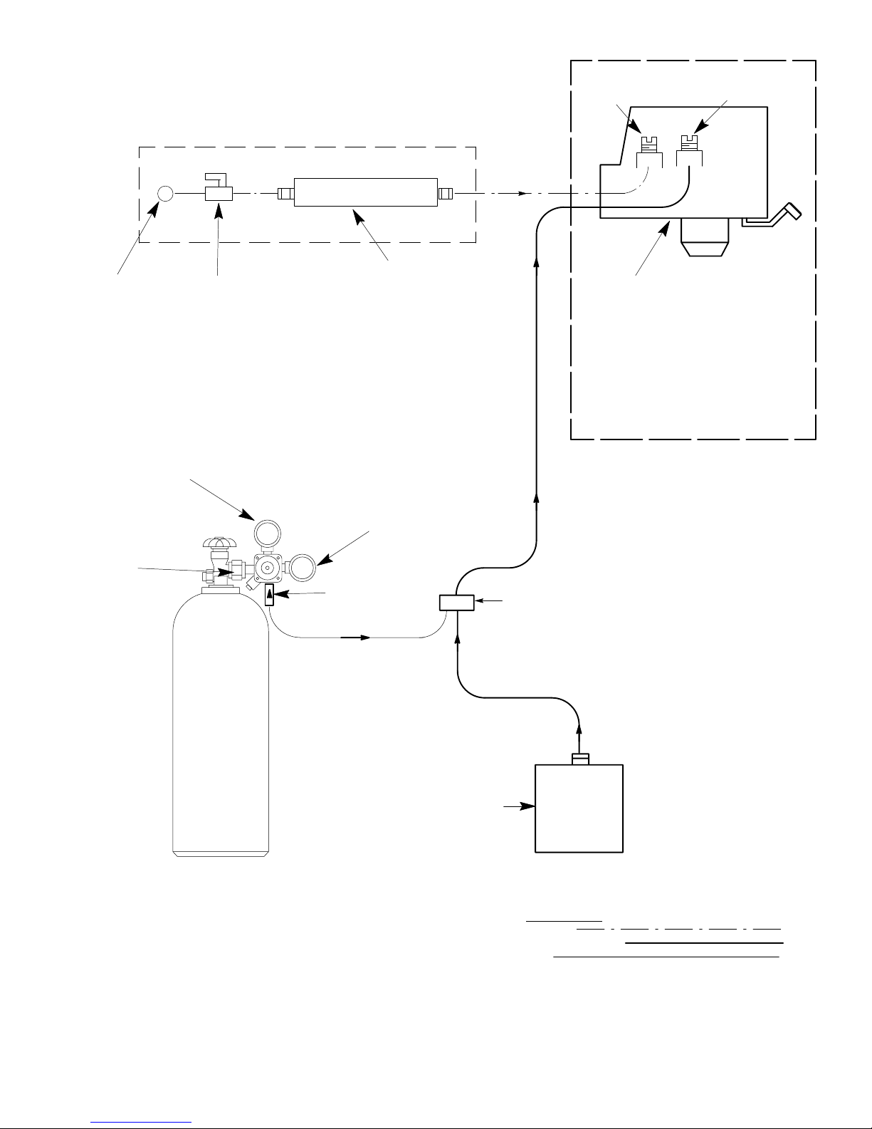
WATER SOURCE
WATER FILTER INSTALLATION FOR FILTERS
WITHOUT BUILT-IN W ATER SHUTOFF VALVE
FILTER
SHUTOFF
VALVE
ADJUSTABLE
WATER FLOW
REGULATOR
SF‘–1 DISPENSING VALVE
DISPENSER
ADJUSTABLE
CONCENTRATE
FLOW REGULATOR
PRIMARY CO
REGULATOR
COUPLING
2
ASS’Y
CARBON DIOXIDE (CO2) GAS
CYLINDER
CO2 CYLINDER PRESSURE
GAS CHECK
VALVE
GAGE
CONCENTRA TE PUMP
(SEE NOTE)
NOTE: CONCENTRATE PUMP MAY
ALSO BE DRIVEN BY NITROGEN
GAS, COMPRESSED AIR, OR AN
ELECTRICALLY OPERATED PUMP
MAY BE USED IN PLACE OF THE
GAS OPERATED PUMP.
BAG-IN-BOX
CONCENTRATE
CONTAINER
LINE LEGEND
WATER
CONCENTRATE
GAS
FIGURE 2. FLOW DIAGRAM (BAG-IN-BOX CONCENTRATE SYSTEM)
2312020000

INSTALLATION
This section describes receiving, unpacking,
selecting location, and installation of the Unit.
RECEIVING
Each Unit is completely tested under operating
conditions and thoroughly inspected before
shipment. At time of shipment, the carrier accepts
the Unit and any claim for damage in transit must be
made with the carrier. Upon receiving Unit from the
delivering carrier, carefully inspect the carton for
visible indication of damage. Any damage or
irregularities should be noted at time of delivery (or
not later than 15 days from date of delivery) and
immediately reported to the delivering carrier.
Request a written inspection report from the Claims
Inspector to substantiate claim. File claim with the
delivering carrier, not with IMI Cornelius Inc.
UNPACKING AND INSPECTION
Unpack Unit as follows:
1. Carefully remove packaging material.
2. Retain Service Manual and loose-shipped parts.
3. Inspect all parts of the Unit for evidence of
damage. If such evidence is found, file a claim
against the carrier.
IDENTIFICATION OF LOOSE-SHIPPED
PARTS
1. CUP REST (item 1) fits inside DRIP TRAY (item
2).
2. DRIP TRAY (item 2) supports cup rest and
receives product spillage.
3. TAPERED PLASTIC GASKETS (item 3) seal
water and concentrate connections at rear of
Unit.
4. ADAPTER FITTING (item 4) connects 3/8 in.
O.D. plain water source line to the Unit.
5. DECAL KIT (item 5). Decals for product
identification on the Unit and front of dispensing
valve – Instructions for applying decals included.
6. SERVICE MANUAL (item 6). A guide to
installation, operation, and maintenance of the
Unit.
7. MOUNTING SCREWS (item 7) for mounting
Unit Base to counter, if desired.
8. HOLE PLUGS (item 8) to close inlet openings in
back of Unit if inlet lines are routed down
through counter top.
9. SCREW (item 9) to secure cover on top of the
Unit.
4. Remove loose-shipped parts from poly bags
and check their identity and quantity against
Table 2.
Table 2. Loose-Shipped Parts
Qty
Item
No.
1 397180-039 Cup Rest 1
2 397179-039 Drip Tray 1
3 178025-100 Tapered Plastic
4 770716-020 Adapter Fitting,
5 312071-000 Decal Kit 1 1
6 312020–000 Service Manual 1 1
7 312971-000 Mounting Screws 2 2
8 300098-000 Hole Plugs 2 2
9 151707 Screw, Thd Rolling,
Part No. Name
Gasket
7/16-20 Female by
5/8-18 Male
8–32 By 3/8 in. long
41-6401
41-6402
Unit
22
11
22
SELECTING LOCATION
This Unit may be island-mounted or installed on a
front or rear countertop provided that the following
requirements are satisfied. Unit may be fastened to
countertop using screws through Unit Base.
Qty
Unit
1. Locate Unit near a source of cold (100° F max)
plain water having a pressure of 40 to 125 psig.
2. Locate Unit to minimize length of concentrate
line.
To comply with National Sanitation Foundation (NSF)
requirements within the United States, Unit base
must be sealed to countertop when screws are used
to fasten Unit Base to countertop. Proceed as follows
to seal base to countertop.
1. Tilt up to expose bottom of base.
2. Liberally apply silastic sealant (such as Dow
Corning RTV 731 or equivalent) on base bottom
edges.
Note: Do not move Unit after positioning or seal
from base to countertop will be broken.
3 312020000
 Loading...