

Page 1

Thermal Cut-Off Switch Kit Installation Instructions
!
WARNING:
!
WARNING:
!
WARNING:
!
CAUTION:
INSTALLATION INSTRUCTIONS
THERMAL CUT-OFF (TCO) SWITCH KIT (P/N 629096942)
ON VIPER FCB DISPENSERS
Read and understand these instructions thoroughly before installing this kit. Retain these instructions as part of
your equipment manuals.
NOTE: This Thermal Cut-Off Switch (TCO) Kit (P/N 629096942) may be installed on the 2, 3 and 4
Flavor Viper Dispenser models.
NOTE: Only qualified personnel should install this kit.
Before starting the installation read and understand all safety labels and warnings on the machine. Also review
and understand all safety instructions in the owners, installation and service manuals. Failure to comply could
result in serious injury, death or damage to the equipment.
QUALIFIED SERVICE PERSONNEL
Only trained and certified electrical, plumbing and refrigeration technicians should service this unit. ALL WIRING
AND PLUMBING MUST CONFORM TO NATIONAL AND LOCAL CODES. FAILURE TO COMPLY COULD
RESULT IN SERIOUS INJURY, DEATH OR EQUIPMENT DAMAGE.
SAFETY PRECAUTIONS
This unit has been specifically designed to provide protection against personal injury. To ensure continued
protection observe the following:
Disconnect power to the unit before servicing following all lock out/tag out procedures established by the user.
Verify all of the power is off to the unit before any work is performed.
Failure to disconnect the power could result in serious injury, death or equipment damage.
Always be sure to keep area around the unit clean and free of clutter. Failure to keep this area clean may result in
injury or equipment damage.
NOTE: The following instructions outline the procedure to install the TCO kit on the refrigeration
system of the Viper dispenser. It is necessary that the TCO is attached to the evaporator outlet
tubing using thermal grease to obtain the best performance out of the Viper unit.
Installation Instructions:
1. Disconnect electrical power from the dispenser.
2. Remove side panels from the unit.
3. Locate the faulty sensor.
4. Remove the black duct tape and insulation tubing.
5. Remove the faulty sensor and unplug it from the wire harness.
6. Refer to the following photos to install the new sensor into the unit.
7. Install the side panels and restore electrical power to the unit.
8. Check for proper operation.
Revision Date: April 07, 2014 www.cornelius.com Revision: C
© 2009-2014, Cornelius Inc. - 1 - Publication Number: 629096942INS
Page 2
Thermal Cut-Off Switch Kit Installation Instructions
Safety TCO (Thermal Cut Out) Work Instructions
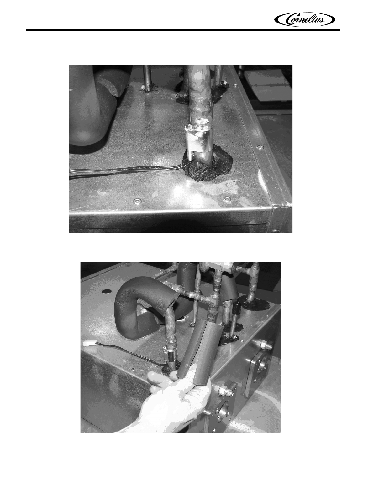
Figure 1
Figure 1 shows the evaporator outlet tubing with Armaflex insulation sleeve removed and TCO removed.
Figure 2
Cut a 4” long Armaflex sleeve 5/8” ID x 3/8” wall, as shown in Figure 2.
Publication Number: 629096942INS - 2 - © 2009-2014, Cornelius Inc.
Page 3

Thermal Cut-Off Switch Kit Installation Instructions
Figure 3
Figure 3 shows how to apply thermal mastic to the copper face of the TCO using grease supplied from kit.
Figure 4
Figure 4 shows how to assemble the Armaflex sleeve on the tubing, which covers the thermistor. Assemble the
TCO just above the insulation sleeve (facing the back of the unit). Critical!!! Make sure the TCO’s copper cup
is correctly engaged with the tubing. Route the wire harness toward the front of the unit and restrain it to the
insulation sleeve with black adhesive tape.
© 2009-2014, Cornelius Inc. - 3 - Publication Number: 629096942INS
Page 4

Thermal Cut-Off Switch Kit Installation Instructions
Figure 5
Figure 5 shows the rear view of the black adhesive tape.
Figure 6
Pull the insulation sleeve flash with the top side of the TCO, as shown in Figure 6.
Publication Number: 629096942INS - 4 - © 2009-2014, Cornelius Inc.
Page 5

Thermal Cut-Off Switch Kit Installation Instructions
Figure 7
Figure 7 shows the back view of the top insulation sleeve.
Figure 8
Figure 8 shows a side view of the top insulation sleeve.
© 2009-2014, Cornelius Inc. - 5 - Publication Number: 629096942INS
Page 6

Thermal Cut-Off Switch Kit Installation Instructions
Figure 9
Wrap the entire evaporator outlet line (from the foam pack until the adhesive foam tape is covered) with black
duct tape, as shown in Figure 9.
Figure 10
Figure 10 shows a side view of the finished assembly.
Publication Number: 629096942INS - 6 - © 2009-2014, Cornelius Inc.
 Loading...