

Cornelius SPIRE 4.1 Installation Manual
SPIRE 4.1
Installation Manual
Release Date: September 18, 2017
Publication Number: 620066826INS
Revision Date: December 18, 2017
Revision: B

Notice
RECYCLE
The products, technical information, and instructions contained in this manual are subject to change without notice.
These instructions are not intended to cover all details or variations of the equipment, nor to provide for every possi
ble contingency in the installation, operation or maintenance of this equipment. This manual assumes that the person(s) working on the equipment have been trained and are skilled in working with electrical, plumbing, pneumatic,
and mechanical equipment. It is assumed that appropriate safety precautions are taken and that all local safety and
construction requirements are being met, in addition to the information contained in this manual.
This Product is warranted only as provided in Cornelius’ Commercial Warranty applicable to this Product and is subject to all of the restrictions and limitations contained in the Commercial Warranty.
Cornelius will not be responsible for any repair, replacement or other service required by or loss or damage resulting
from any of the following occurrences, including but not limited to, (1) other than normal and proper use and normal
service conditions with respect to the Product, (2) improper voltage, (3) inadequate wiring, (4) abuse, (5) accident,
(6) alteration, (7) misuse, (8) neglect, (9) unauthorized repair or the failure to utilize suitably qualified and trained per
sons to perform service and/or repair of the Product, (10) improper cleaning, (11) failure to follow installation, operating, cleaning or maintenance instructions, (12) use of “non-authorized” parts (i.e., parts that are not 100%
compatible with the Product) which use voids the entire warranty, (13) Product parts in contact with water or the
product dispensed which are adversely impacted by changes in liquid scale or chemical composition.
Correct Disposal of this Product
This marking indicates that this product should not be disposed with other household wastes throughout the EU. To
prevent possible harm to the environment or human health from uncontrolled waste disposal, recycle it responsibly
to promote the sustainable reuse of material resources. To return your used device, please use the return and
collection systems or contact the retailer where the product was purchased. They can take this product for
environmental safe recycling.
-
-
Trademarks and Copyrights
This document contains proprietary information and it may not be reproduced in any way without permission from
Cornelius. This document contains the original instructions for the unit described.
CORNELIUS INC
101 Regency Drive
Glendale Heights, IL
Tel: + 1 800-238-3600
Printed in U.S.
Contact Information
To inquire about current revisions of any documentation or assistance with any Cornelius product, contact:
www.cornelius.com
800-238-3600

TABLE OF CONTENTS
SAFETY INSTRUCTIONS . . . . . . . . . . . . . . . . . . . . . . . . . . . . . . . . . . . . . . . . . . . . . . . . . . . . . . . . . . . 5
Safety Overview . . . . . . . . . . . . . . . . . . . . . . . . . . . . . . . . . . . . . . . . . . . . . . . . . . . . . . . . . . . . . . . . 5
Safety Alert symbol . . . . . . . . . . . . . . . . . . . . . . . . . . . . . . . . . . . . . . . . . . . . . . . . . . . . . . . . . . . . . . 5
Types of Alerts . . . . . . . . . . . . . . . . . . . . . . . . . . . . . . . . . . . . . . . . . . . . . . . . . . . . . . . . . . . . . . 5
Safety Tips . . . . . . . . . . . . . . . . . . . . . . . . . . . . . . . . . . . . . . . . . . . . . . . . . . . . . . . . . . . . . . . . . . . . 5
Qualified Service Personnel . . . . . . . . . . . . . . . . . . . . . . . . . . . . . . . . . . . . . . . . . . . . . . . . . . . . . . . 5
Safety Precautions . . . . . . . . . . . . . . . . . . . . . . . . . . . . . . . . . . . . . . . . . . . . . . . . . . . . . . . . . . . . . . 6
Shipping And Storage . . . . . . . . . . . . . . . . . . . . . . . . . . . . . . . . . . . . . . . . . . . . . . . . . . . . . . . . . 6
CO2 (Carbon Dioxide) Warning . . . . . . . . . . . . . . . . . . . . . . . . . . . . . . . . . . . . . . . . . . . . . . . . . 6
Mounting in or on a Counter . . . . . . . . . . . . . . . . . . . . . . . . . . . . . . . . . . . . . . . . . . . . . . . . . . . . 6
Unit Location . . . . . . . . . . . . . . . . . . . . . . . . . . . . . . . . . . . . . . . . . . . . . . . . . . . . . . . . . . . . . . . . 6
Machine Usage . . . . . . . . . . . . . . . . . . . . . . . . . . . . . . . . . . . . . . . . . . . . . . . . . . . . . . . . . . . . . . 6
SPIRE 4.1 SYSTEM OVERVIEW . . . . . . . . . . . . . . . . . . . . . . . . . . . . . . . . . . . . . . . . . . . . . . . . . . . . . . 7
Spire 4.1: Description . . . . . . . . . . . . . . . . . . . . . . . . . . . . . . . . . . . . . . . . . . . . . . . . . . . . . . . . . . . . 7
Spire 4.1: Specifications . . . . . . . . . . . . . . . . . . . . . . . . . . . . . . . . . . . . . . . . . . . . . . . . . . . . . . . . . . 7
Spire 4.1: Physical Dimensions . . . . . . . . . . . . . . . . . . . . . . . . . . . . . . . . . . . . . . . . . . . . . . . . . . . . 8
DELIVERY, INSPECTION & UNPACKING . . . . . . . . . . . . . . . . . . . . . . . . . . . . . . . . . . . . . . . . . . . . . . . 9
Delivery and Inspection . . . . . . . . . . . . . . . . . . . . . . . . . . . . . . . . . . . . . . . . . . . . . . . . . . . . . . . . . . . 9
Moving the Unit . . . . . . . . . . . . . . . . . . . . . . . . . . . . . . . . . . . . . . . . . . . . . . . . . . . . . . . . . . . . . . 9
Unpacking the Unit Carton . . . . . . . . . . . . . . . . . . . . . . . . . . . . . . . . . . . . . . . . . . . . . . . . . . . . . 9
PREPARING THE COUNTER . . . . . . . . . . . . . . . . . . . . . . . . . . . . . . . . . . . . . . . . . . . . . . . . . . . . . . . 10
Marking and Cutting the Counter - Spire 4.1 . . . . . . . . . . . . . . . . . . . . . . . . . . . . . . . . . . . . . . . . . 10
Sanitizing the Ice Bin . . . . . . . . . . . . . . . . . . . . . . . . . . . . . . . . . . . . . . . . . . . . . . . . . . . . . . . . . . . 11
Positioning the Spire Dispenser On the Counter . . . . . . . . . . . . . . . . . . . . . . . . . . . . . . . . . . . . . . 13
Ice Maker Mounting . . . . . . . . . . . . . . . . . . . . . . . . . . . . . . . . . . . . . . . . . . . . . . . . . . . . . . . . . . . . 14
CONNECTING THE UNIT . . . . . . . . . . . . . . . . . . . . . . . . . . . . . . . . . . . . . . . . . . . . . . . . . . . . . . . . . . 15
Removing the Enclave . . . . . . . . . . . . . . . . . . . . . . . . . . . . . . . . . . . . . . . . . . . . . . . . . . . . . . . . . . 15
Replacing the Enclave . . . . . . . . . . . . . . . . . . . . . . . . . . . . . . . . . . . . . . . . . . . . . . . . . . . . . . . . . . 16
Installing Water, CO2 and Syrup Lines . . . . . . . . . . . . . . . . . . . . . . . . . . . . . . . . . . . . . . . . . . . . . . 17
Installing the Drain . . . . . . . . . . . . . . . . . . . . . . . . . . . . . . . . . . . . . . . . . . . . . . . . . . . . . . . . . . . . . 18
Filling the Ice Bin (Manual) . . . . . . . . . . . . . . . . . . . . . . . . . . . . . . . . . . . . . . . . . . . . . . . . . . . . . . . 19
Start Syrup Flow . . . . . . . . . . . . . . . . . . . . . . . . . . . . . . . . . . . . . . . . . . . . . . . . . . . . . . . . . . . . . . . 19
INITIAL SETUP . . . . . . . . . . . . . . . . . . . . . . . . . . . . . . . . . . . . . . . . . . . . . . . . . . . . . . . . . . . . . . . . . . . 20
Water Supply and CO2 Regulator Setup . . . . . . . . . . . . . . . . . . . . . . . . . . . . . . . . . . . . . . . . . . . . 20
Accessing The Service Menu and Service Mode . . . . . . . . . . . . . . . . . . . . . . . . . . . . . . . . . . . . . . 22
Service Mode - Initial Setup or Service Screen . . . . . . . . . . . . . . . . . . . . . . . . . . . . . . . . . . . . . . . 22
Service Mode - Initial Setup . . . . . . . . . . . . . . . . . . . . . . . . . . . . . . . . . . . . . . . . . . . . . . . . . . . . . . 23

Service Mode - Service Screen . . . . . . . . . . . . . . . . . . . . . . . . . . . . . . . . . . . . . . . . . . . . . . . . . . . 24
Mapping the Valves . . . . . . . . . . . . . . . . . . . . . . . . . . . . . . . . . . . . . . . . . . . . . . . . . . . . . . . . . . . . 25
Changing Valve Assignments . . . . . . . . . . . . . . . . . . . . . . . . . . . . . . . . . . . . . . . . . . . . . . . . . . . . . 27
Priming Lines . . . . . . . . . . . . . . . . . . . . . . . . . . . . . . . . . . . . . . . . . . . . . . . . . . . . . . . . . . . . . . . . . 28
Priming Individual Lines . . . . . . . . . . . . . . . . . . . . . . . . . . . . . . . . . . . . . . . . . . . . . . . . . . . . . . 28
Priming Multiple Lines . . . . . . . . . . . . . . . . . . . . . . . . . . . . . . . . . . . . . . . . . . . . . . . . . . . . . . . . 29
Adjust Water to Syrup Ratio (BRIX) . . . . . . . . . . . . . . . . . . . . . . . . . . . . . . . . . . . . . . . . . . . . . . . . 31
Viewing Valve Layout . . . . . . . . . . . . . . . . . . . . . . . . . . . . . . . . . . . . . . . . . . . . . . . . . . . . . . . . . . . 33
Viewing Defined Flow Rates . . . . . . . . . . . . . . . . . . . . . . . . . . . . . . . . . . . . . . . . . . . . . . . . . . . . . . 34
Off-Cycle Agitator Settings . . . . . . . . . . . . . . . . . . . . . . . . . . . . . . . . . . . . . . . . . . . . . . . . . . . . . . . 35
Ice Chute Restrictor Adjustment . . . . . . . . . . . . . . . . . . . . . . . . . . . . . . . . . . . . . . . . . . . . . . . . . . . 36
DIAGRAMS . . . . . . . . . . . . . . . . . . . . . . . . . . . . . . . . . . . . . . . . . . . . . . . . . . . . . . . . . . . . . . . . . . . . . . 37
TROUBLESHOOTING . . . . . . . . . . . . . . . . . . . . . . . . . . . . . . . . . . . . . . . . . . . . . . . . . . . . . . . . . . . . . 39
Diagnostics Guide for Agitator Timer Board . . . . . . . . . . . . . . . . . . . . . . . . . . . . . . . . . . . . . . . . . . 41
Spire 4.1 Installation Manual
!
DANGER
!
WARNING
!
CAUTION
!
WARNING
!
SAFETY INSTRUCTIONS
SAFETY OVERVIEW
• Read and follow ALL SAFETY INSTRUCTIONS in this manual and any warning/caution labels on the unit (decals,
labels or laminated cards).
• Read and understand ALL applicable OSHA (Occupational Safety and Health Administration) safety regulations before
operating this unit.
SAFETY ALERT SYMBOL
This is the safety alert symbol. When you see this in the manual or on the unit, be alert to the
potential of personal injury or damage to the unit.
Types of Alerts
Indicates an immediate hazardous situation which if not avoided WILL result in serious injury, death or
equipment damage.
Indicates a potentially hazardous situation which, if not avoided, COULD result in serious injury, death,
or equipment damage.
Indicates a potentially hazardous situation which, if not avoided, MAY result in minor or moderate
injury or equipment damage.
SAFETY TIPS
• Keep safety signs in good condition and replace missing or damaged items.
• Learn how to operate the unit and how to use the controls.
•Do not let anyone operate the unit without proper training. This appliance is not intended for use by very young children
or infirm persons without supervision. Young children should be supervised to ensure that they do not play with the
appliance.
• Keep your unit in proper working condition and do not allow unauthorized modifications to the unit.
QUALIFIED SERVICE PERSONNEL
Only trained and certified electrical, plumbing and refrigeration technicians should service this unit.
All wiring and plumbing must conform to National and Local Codes. Failure to comply could result in
serious injury, death or equipment damage.
© 2017, Cornelius Inc. - 5 - Publication Number: 620066826INS
Spire 4.1 Installation Manual
WARNING
!
CAUTION
!
CAUTION
!
DANGER
!
WARNING
!
CAUTION
!
CAUTION
!
SAFETY PRECAUTIONS
This unit has been specifically designed to provide protection against personal injury. To ensure continued protection
observe the following:
Disconnect power to the unit before servicing following all lock out/tag out procedures established
by the user. Verify all the power is off to the unit before any work is performed. Failure to disconnect
the power could result in serious injury, death or equipment damage.
Always be sure to keep area around the unit clean and free of clutter. Failure to keep this area clean
may result in injury or equipment damage.
Shipping And Storage
Before shipping, storing, or relocating the unit, the unit must be sanitized and all sanitizing solution
must be drained from the system. A freezing ambient environment will cause residual sanitizing
solution or water remaining inside the unit to freeze resulting in damage to internal components.
The unit should be stored in a climate controlled area if long term storage is needed. Long term
exposure to cold/hot conditions can permanently damage critical system components such as the
computer and touchscreen.
CO2 (Carbon Dioxide) Warning
CO2 displaces oxygen. Strict attention MUST be observed in the prevention of CO2 gas leaks in the
entire CO
DIATELY
high concentrations of CO
ness and DE
2 and soft drink system. If a CO2 gas leak is suspected, particularly in a small area, IMME-
ventilate the contaminated area before attempting to repair the leak. Personnel exposed to
2 gas experience tremors which are followed rapidly by loss of conscious-
ATH.
Mounting in or on a Counter
While installing the unit in or on a counter top, the counter must be able to support a weight in
excess of 1,000 lbs. to insure adequate support for the unit.
Failure to comply could result in serious injury, death or equipment damage.
Unit Location
• This unit is not designed for use in outdoor locations.
• The appliance must be placed in a horizontal position.
• The appliance is not suitable for installation in an area where a water jet would be used.
Machine Usage
• This appliance is not intended for use by persons (including children) with reduced physical, sensory
or mental capabilities, or lack of experience and knowledge, unless they have been given
supervision or instruction concerning use of the appliance by a person responsible for their safety.
• Children should be supervised to ensure that they do not play with the appliance.
Publication Number: 620066826INS - 6 - © 2017, Cornelius Inc.
Spire 4.1 Installation Manual
SPIRE 4.1 SYSTEM OVERVIEW
SPIRE 4.1: DESCRIPTION
Spire 4.1 solves your ice and beverage service needs in a sanitary, space saving, economical way. It is designed to
manually fill with ice from any remote ice-making source. The unit includes the following components:
• Single, multi-brand dispensing valve
• Cold plate
• Internal carbonator tank
• External pump for carbonator
This dispenser dispenses cubes (up to 1-1/4 inch in size), cube-lets, and compressed (not flaked) ice and supplies
beverages direct from the Bag-In-Box (BIB) syrup supply with no additional cooling.
of the Spire 4.1 unit.
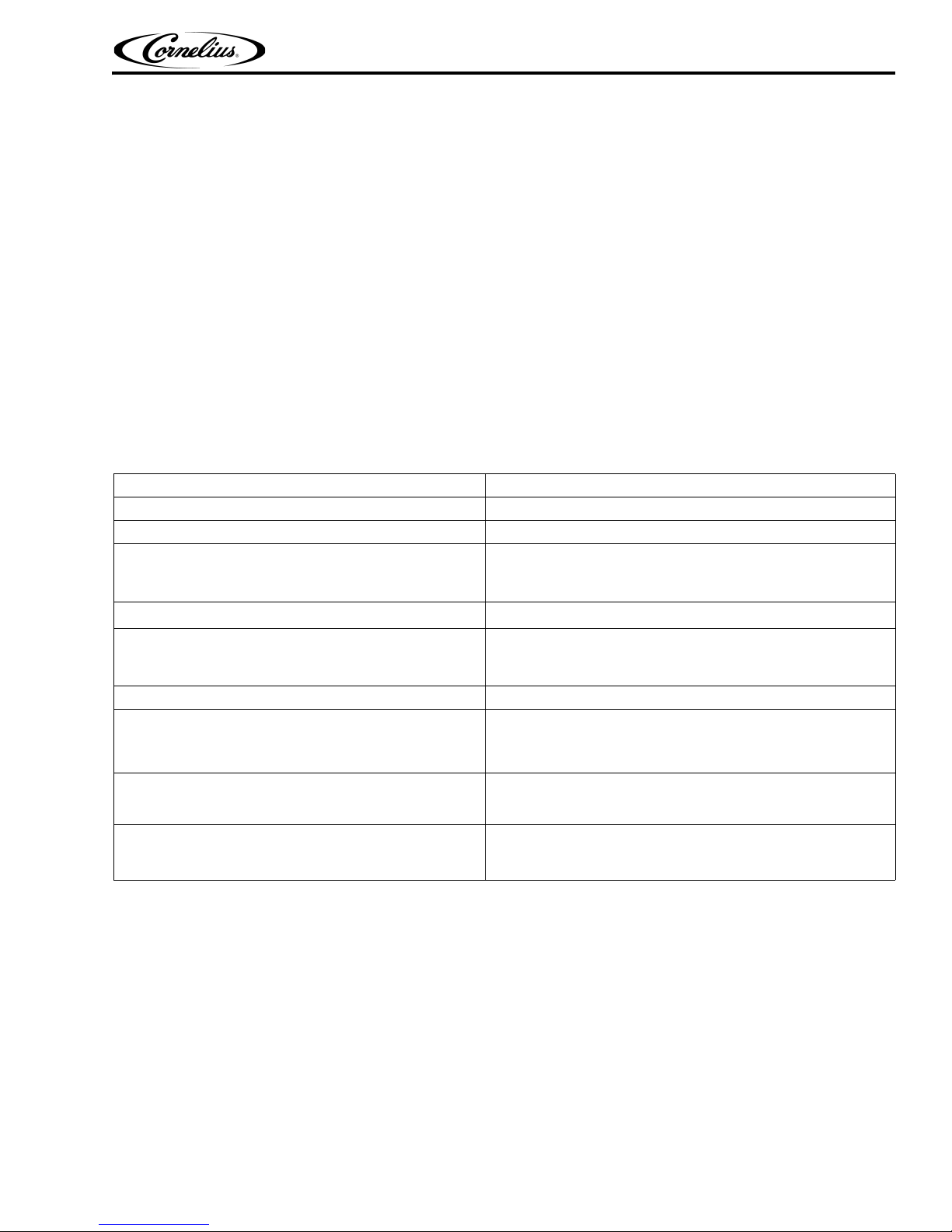
SPIRE 4.1: SPECIFICATIONS
Model name Spire 4.1
Total unit weight (empty) Approximately 335 lb. (151.9 kg)
Ice storage 255 lb. (115.7 kg)
75 psig (0.52 MPa) max
2 operating pressure
CO
Ambient operational temperature
Maximum Storage Temperatures
Note: Damage to components may occur if storage condi-
tions exceed temperature limits.
Maximum number of brands/flavors available 14/6
Electrical
Dimensions
Noise Level
Note: CO2 pressure is regulated down to 75 psi by a supplied
preset regulator.
65 to 95o F (18 to 35o C)
-4oF (-20oC) to 122oF (50oC)
120 V/1-phase/60 Hz
220 - 240 V/1-phase/50 Hz
15 A dedicated, protected circuit
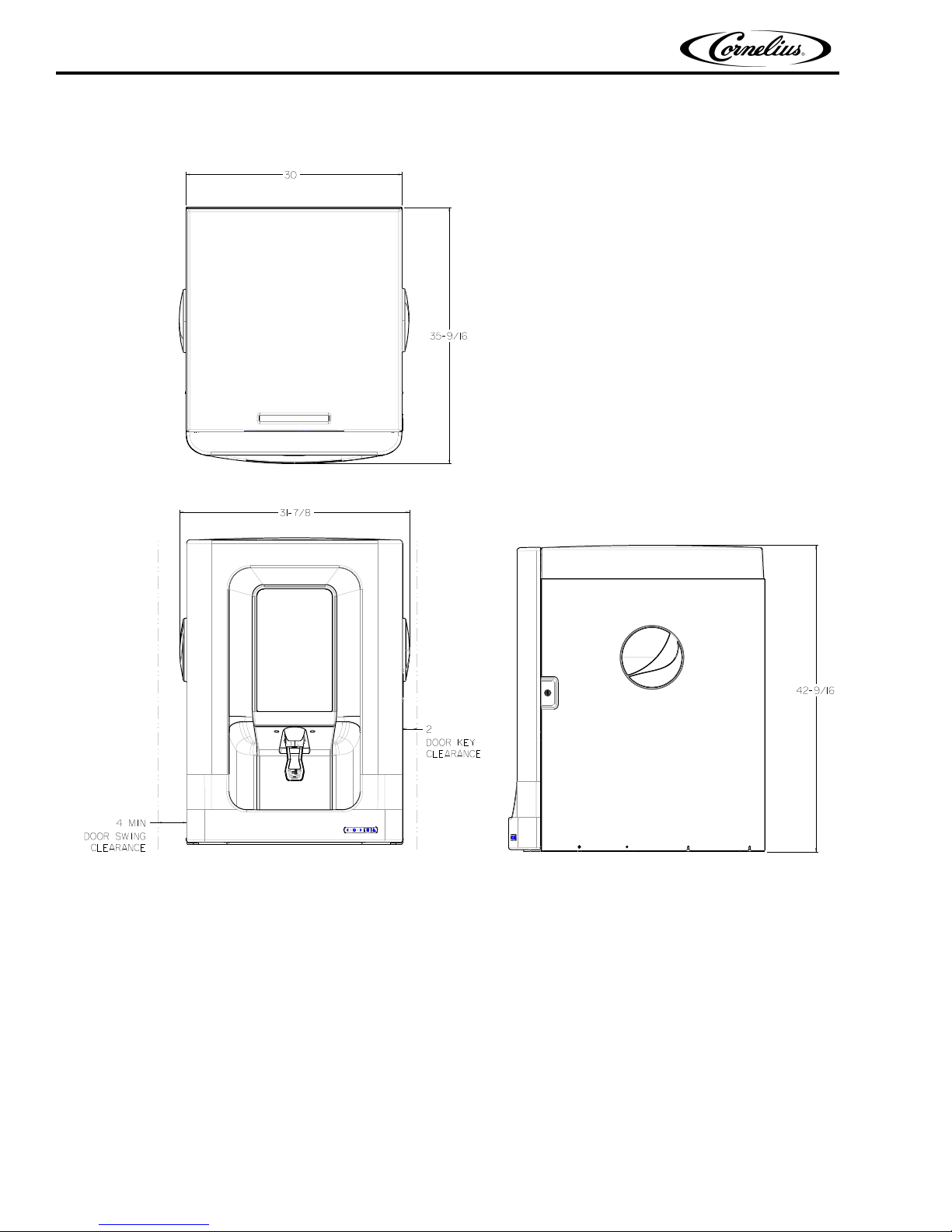
42-9/16 in. (1.08 m) tall, to top of lid (Manual Fill Unit)
31-7/8 in. (0.81 m) wide
35-9/16 in. (0.90 m) deep
The unit emits acoustical noise with an A-weighted sound
pressure level no greater than 75 dB, as measured in
accordance with EN 60335-2-75
Figure 1. shows the dimensions
© 2017, Cornelius Inc. - 7 - Publication Number: 620066826INS
Spire 4.1 Installation Manual
SPIRE 4.1: PHYSICAL DIMENSIONS
Publication Number: 620066826INS - 8 - © 2017, Cornelius Inc.
Figure 1. Spire 4.1 Physical Dimensions
Spire 4.1 Installation Manual
WARNING
!
CAUTION
!
DELIVERY, INSPECTION & UNPACKING
It is the responsibility of the installer to ensure that the water supply to the dispensing equipment is
provided with protection back flow by an air gap as defined in ANSI A 112.1.2-1979; or an
approved vacuum breaker or other such method as proved effective by test and must comply with
all federal, state and local codes.
Failure to comply could result in serious injury, death or damage to the equipment.
Water pipe connections and fixtures directly
installed and maintained according to Federal, State and Local laws.
Unit Temperature Stabilization
Allow the unit to stabilize within the ambient operational temperature range (see “Spire 4.1: Specifications” on page 8) for 30 minutes before plugging in and en
components.
DELIVERY AND INSPECTION
NOTE: Cornelius is not responsible for damaged freight. If damage is found, you must save all packaging
material and contact the freight carrier. Failure to contact the carrier within 48 hours of receipt may
void your claim.
connected to a potable water supply shall be sized,
ergizing to prevent damage to critical
Moving the Unit
The box containing the unit should be moved using a manual forklift.
Unpacking the Unit Carton
Note the following when unpacking the carton:
1. Check for damage, even if it appears minor. If the carton is damaged, write “exterior carton damage-concealed
damage possible” on
2. Remove and inspect the motor assembly from the top compartment of the carton.
3. Inspect the unit and determine if there is any internal shipping damage.
If yes, report immediately to the carrier.
the consignee copy of the freight invoice and contact the freight company immediately.
© 2017, Cornelius Inc. - 9 - Publication Number: 620066826INS
Spire 4.1 Installation Manual
PREPARING THE COUNTER
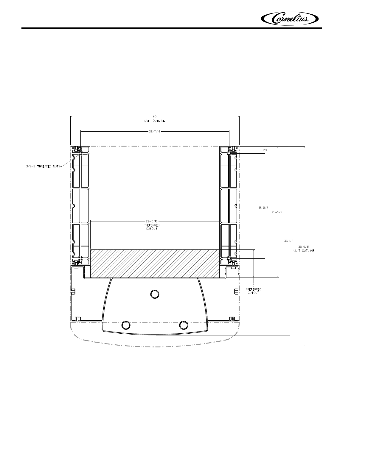
To place the Spire 4.1 unit on a counter, the counter must be prepared by cutting a slot in the counter to accommodate the syrup lines and power cord connection to the unit.
MARKING AND CUTTING THE COUNTER - SPIRE 4.1
To mark and cut the counter, refer Figure 2.
Publication Number: 620066826INS - 10 - © 2017, Cornelius Inc.
Figure 2.
Spire 4.1 Installation Manual
Display Door
Ice Bin Cover
Agitator
Retaining
Screw
Agitator
Cover
2-Piece
Agitator
Assembly
Spindle
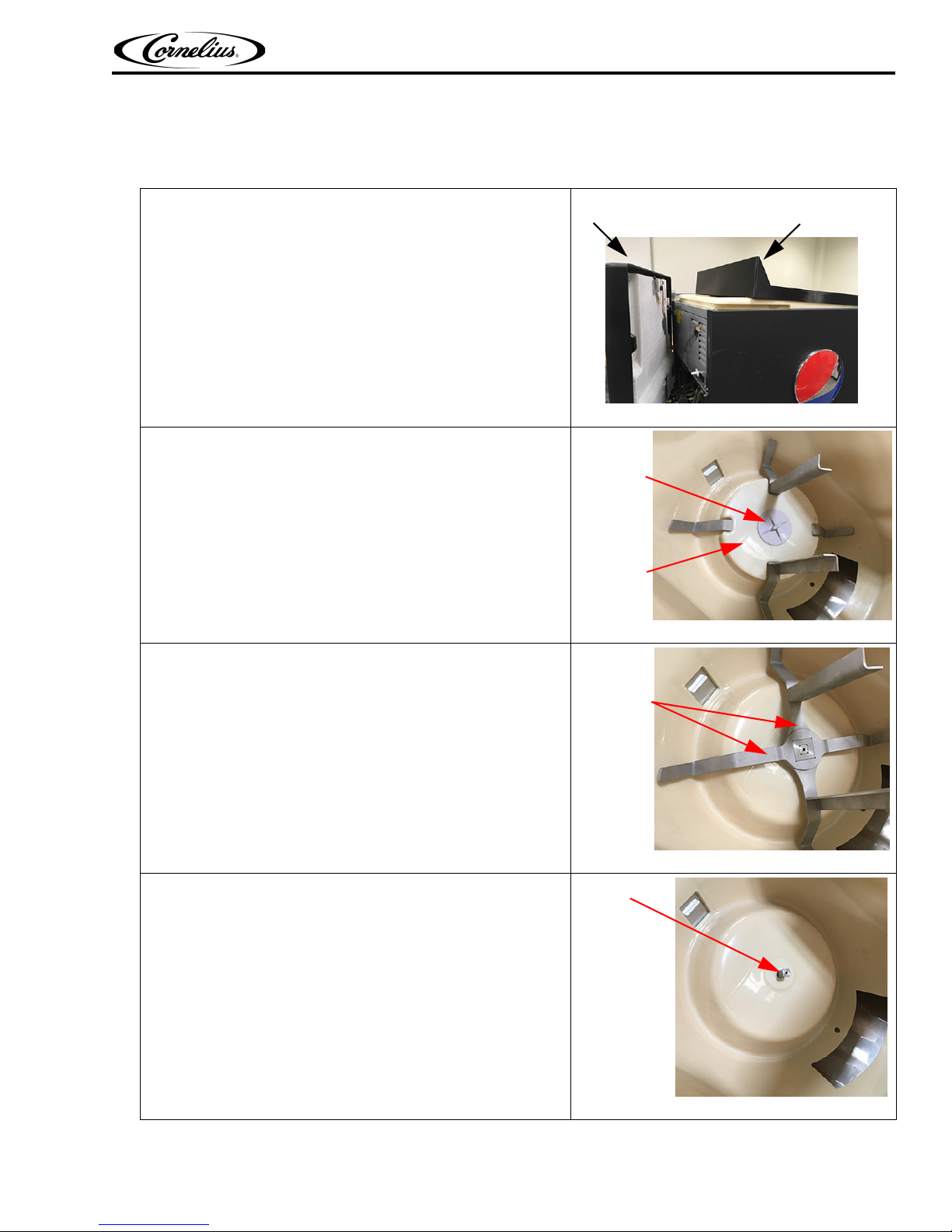
SANITIZING THE ICE BIN
It is easier to sanitize the ice bin before placing the unit on the counter. This procedure can be performed after positioning the unit on the counter, if desired. Perform the following steps to sanitize the ice bin:
1. Open the display door and remove the cover from the ice
bin.
Figure 3
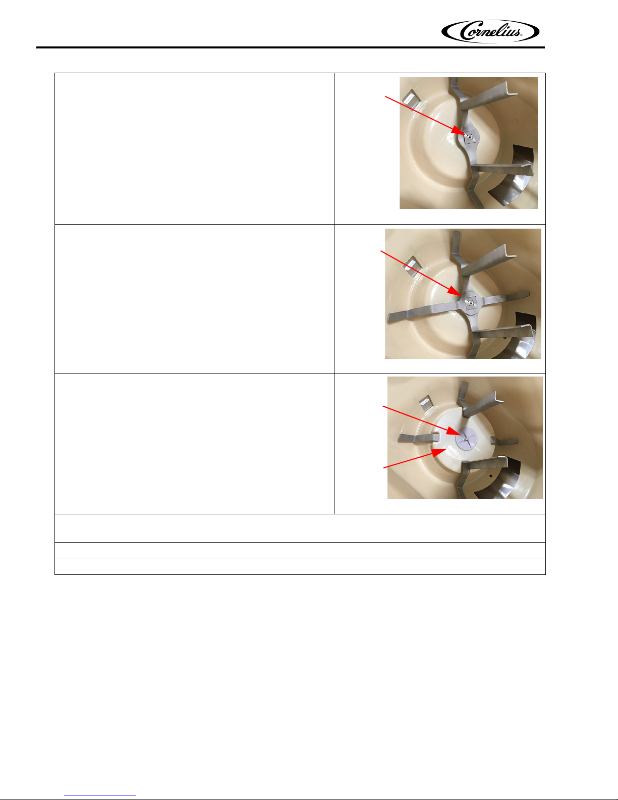
2. Remove the agitator retaining screw. To do this, turn the
thumbscrew counterclockwise, then lift the agitator cover
off the 2-piece agitator assembly
3. Remove the 2-piece agitator assembly from the bin.
To do this, lift the first (top) piece of the 2-piece agitator
assembly from the bin, then lift the second (bottom) piece
out of the bin.
Result: See Figure 6.
4. With the 2-piece agitator removed from the bin, clean the
interior of the bin, top cover and agitator assembly.
Note: Use a soap solution with a nylon bristle brush,
sponge or cloth to clean the interior of the bin, top cover
and agitator assembly.
Then, thoroughly rinse the bin, cover and agitator surfaces
with clean potable water.
Figure 4
Figure 5
Figure 6
© 2017, Cornelius Inc. - 11 - Publication Number: 620066826INS
Spire 4.1 Installation Manual
Bottom
Agitator
over the
spindle
Top and
Bottom
Agitator
Assembly
Agitator
Retaining
Screw
Agitator
Cover
5. Place the bottom agitator over the spindle as shown in
Figure 7.
6. Then, place the top agitator in place over the bottom agitator making sure the two agitator components are seated
properly as shown in
Figure 8.
Figure 7
Figure 8
7. Finally, with the 2-piece agitator assembly seated properly,
place the agitator cover over the 2-piece assembly and
secure it with the agitator retaining screw. Make sure that
the agitator retaining screw is tight as shown in
Figure 9.
Figure 9
8. Using a mechanical spray bottle filled with sanitizing solution, spray the entire interior of the ice bin and agitator assembly with the sanitizing solution and allow it to air dry.
9. Replace the ice bin cover and make sure it remains in place during the rest of the installation
10.Close the display door.
Publication Number: 620066826INS - 12 - © 2017, Cornelius Inc.
Spire 4.1 Installation Manual
WARNING
!
CAUTION
!
WARNING
!
POSITIONING THE SPIRE DISPENSER ON THE COUNTER
The Spire unit is very heavy and extreme care should be taken when moving or lifting the unit. Do
not attempt to lift the unit manually.
Failure to comply could result in serious injury, death or damage to the equipment.
Important: Before taking the unit off the pallet or whenever moving the unit, gather all electrical
cables and tubing from under the unit and position them appropriately to protect them from damage
when moving the unit.
Review all information here first, then perform the following steps to place the Spire unit in position on the counter:
1. Locate the indoor placement of the dispenser. The dispenser can be placed directly on the counter top or it
can be placed on the counter top using the optional Anti-Tip Kit (sold separately).
Counter Mounting
For direct mounting of the dispenser to a level counter top (without legs), openings must be cut into the
counter. To do this, locate the desired position for the unit, then mark openings on the counter using
dimensions provided in Figure 2.
After direct counter top mounting, the unit must be sealed to the counter. Apply a continuous bead of NSF
International (NSF) silicone sealant (Dow 732 or equal) approximately 1/4-inch around the outside of the
unit. All excess sealant must be wiped away immediately.
Counter Mounting with Optional Anti-Tip Kit
Follow kit instructions for proper installation.
Failure to install the Anti-Tip Kit properly could result in a hazardous situation which, if not avoided, could
result in serious injury, death, or equipment damage.
NOTE: The dispenser MUST be place in a horizontal, level position and product and supply lines must be
flexible enough to permit shifting the position of the dispenser (when cleaning the area beneath the dispenser, etc...).
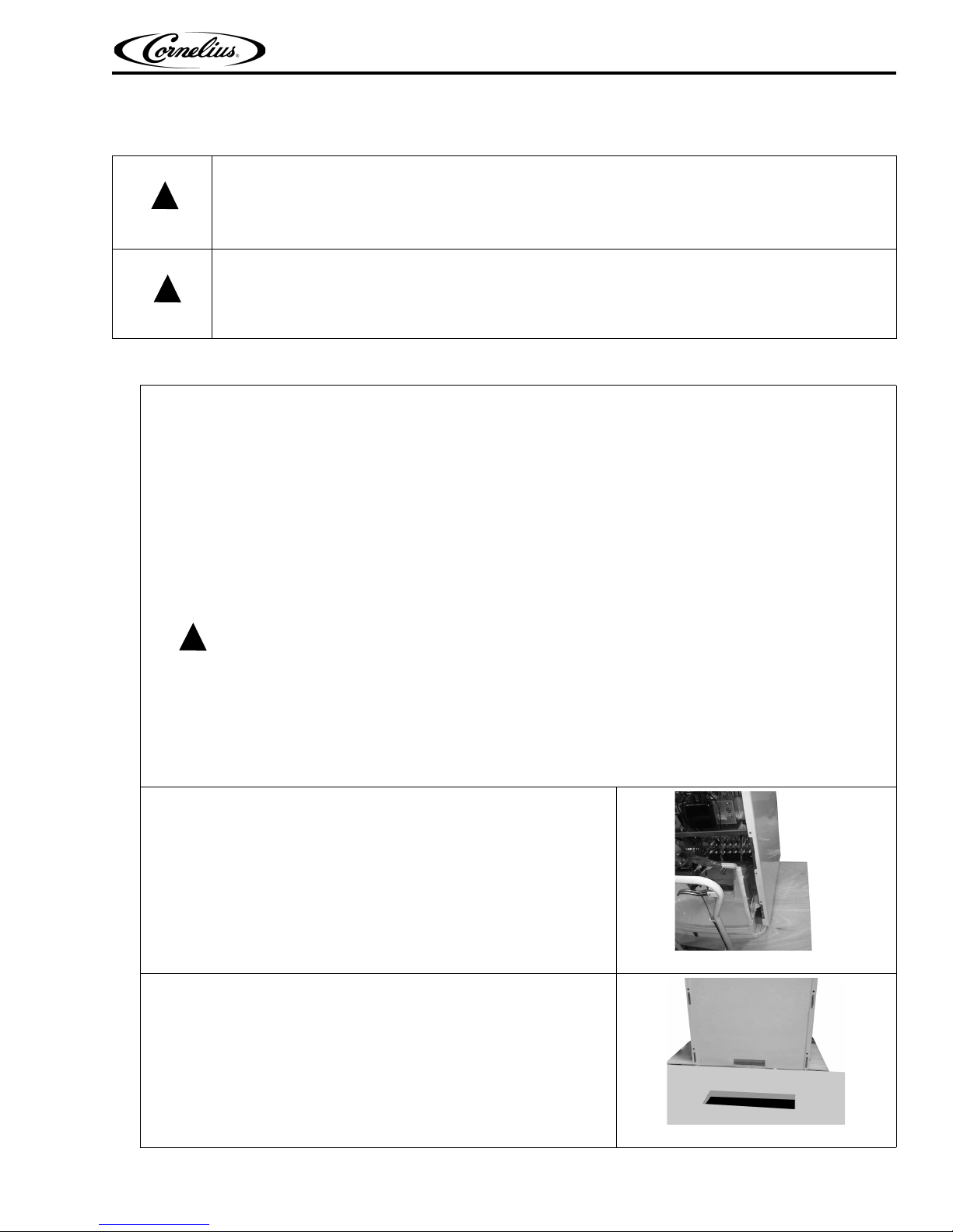
2. Move the fountain lift with the unit to the front edge of the counter
where it will be in
3. Carefully jack up the fountain lift so that the bottom of the unit is
flush or slightly above the level of the counter.
stalled.
Figure 10
Figure 11
© 2017, Cornelius Inc. - 13 - Publication Number: 620066826INS
Spire 4.1 Installation Manual
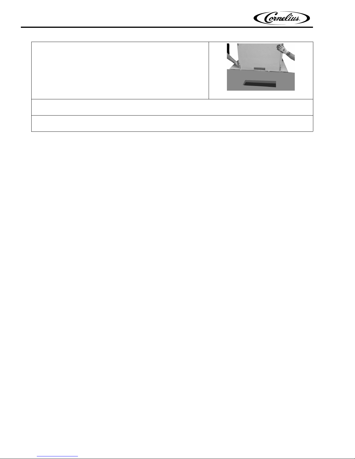
4. Carefully slide the unit off of the fountain lift and onto the counter.
NOTE: Make sure the unit is securely placed on the counter, but
leave open space in the counter cut-out for routing cables and
tubing through the counter top.
Figure 12
5. Gather cables and tubing from the unit that will require under-counter connections and route them through
an open space in the counter-top.
6. Finally, position the unit so that the drip tray sub-base is lined up in front of the cutout and is centered
appropriately over the cutout in the counter to ensure it is stable.
ICE MAKER MOUNTING
For proper ice maker and dispenser function, review the following before mounting an ice maker.
• When using the optional Spire Ice Maker Adapter Kit, refer to the installation instructions for that kit.
• An Ice level sensor (bin stat) should be installed at least 2” below hopper top. (Refer to the installation instructions
for the Ice maker).
• Ice bridge thickness is adjusted per Ice Maker manufacturer’s specification. (Refer to the installation instructions for
the Ice maker).
• Make sure agitator board off-cycle timer settings are set properly for ice type. (See “Off-Cycle Agitator Settings” on
page 35).
• Make sure Ice flow from the dispenser ice chute is sufficient for ice type. (See “Ice Chute Restrictor Adjustment” on
page 36).
• Note that if chew-able ice is used, additional parts and components must be ordered from Cornelius.
Publication Number: 620066826INS - 14 - © 2017, Cornelius Inc.
 Loading...