

Cornelius signature Service Manual

SIGNATURE
Service Manual
Release Date: February 16, 2012
Publication Number: 621058426SER
Revision Date: N/A
Revision: A
Visit the IMI Cornelius web site at www.cornelius.com
for all your Literature needs.

The products, technical information, and instructions contained in this manual are subject to change without notice.
These instructions are not intended to cover all details or variations of the equipment, nor to provide for every possible contingency in the installation, operation or maintenance of this equipment. This manual assumes that the person(s) working on the equipment have been trained and are skilled in working with electrical, plumbing, pneumatic,
and mechanical equipment. It is assumed that appropriate safety precautions are taken and that all local safety and
construction requirements are being met, in addition to the information contained in this manual.
This Product is warranted only as provided in Cornelius’ Commercial Warrant applicable to this Product and is subject to all of the restrictions and limitations contained in the Commercial Warranty.
Cornelius will not be responsible for any repair, replacement or other service required by or loss or damage resulting
from any of the following occurrences, including but not limited to, (1) other than normal and proper use and normal
service conditions with respect to the Product, (2) improper voltage, (3) inadequate wiring, (4) abuse, (5) accident,
(6) alteration, (7) misuse, (8) neglect, (9) unauthorized repair or the failure to utilize suitably qualified and trained
persons to perform service and/or repair of the Product, (10) improper cleaning, (11) failure to follow installation,
operating, cleaning or maintenance instructions, (12) use of “non-authorized” parts (i.e., parts that are not 100%
compatible with the Product) which use voids the entire warranty, (13) Product parts in contact with water or the
product dispensed which are adversely impacted by changes in liquid scale or chemical composition.
Contact Information:
To inquire about current revisions of this and other documentation or for assistance with any Cornelius product contact:
www.cornelius.com
800-238-3600
Trademarks and Copyrights:
This document contains proprietary information and it may not be reproduced in any way without permission from
Cornelius.
Printed in U.S.A.

TABLE OF CONTENTS
Safety Instructions. . . . . . . . . . . . . . . . . . . . . . . . . . . . . . . . . . . . . . . . . . . . . . . . . . . . . . . . . . . . . . . . 1
Read and Follow ALL Safety Instructions . . . . . . . . . . . . . . . . . . . . . . . . . . . . . . . . . . . . . . . . . . . . . . . . . . . . 1
Safety Overview . . . . . . . . . . . . . . . . . . . . . . . . . . . . . . . . . . . . . . . . . . . . . . . . . . . . . . . . . . . . . . . . . 1
Recognition . . . . . . . . . . . . . . . . . . . . . . . . . . . . . . . . . . . . . . . . . . . . . . . . . . . . . . . . . . . . . . . . . . . . 1
Different Types of Alerts . . . . . . . . . . . . . . . . . . . . . . . . . . . . . . . . . . . . . . . . . . . . . . . . . . . . . . . . . . . . . . 1
Safety Tips . . . . . . . . . . . . . . . . . . . . . . . . . . . . . . . . . . . . . . . . . . . . . . . . . . . . . . . . . . . . . . . . . . . . . . . . . . . 1
Qualified Service Personnel . . . . . . . . . . . . . . . . . . . . . . . . . . . . . . . . . . . . . . . . . . . . . . . . . . . . . . . . . . . . . . 2
Safety Precautions . . . . . . . . . . . . . . . . . . . . . . . . . . . . . . . . . . . . . . . . . . . . . . . . . . . . . . . . . . . . . . . . . . . . . 2
Shipping And Storage . . . . . . . . . . . . . . . . . . . . . . . . . . . . . . . . . . . . . . . . . . . . . . . . . . . . . . . . . . . . . . . . . . . 2
Mounting on a Counter . . . . . . . . . . . . . . . . . . . . . . . . . . . . . . . . . . . . . . . . . . . . . . . . . . . . . . . . . . . . . . . . . . 3
Introduction . . . . . . . . . . . . . . . . . . . . . . . . . . . . . . . . . . . . . . . . . . . . . . . . . . . . . . . . . . . . . . . . . . . . . 4
Manual Overview . . . . . . . . . . . . . . . . . . . . . . . . . . . . . . . . . . . . . . . . . . . . . . . . . . . . . . . . . . . . . . . . . . . . . . 4
System Overview . . . . . . . . . . . . . . . . . . . . . . . . . . . . . . . . . . . . . . . . . . . . . . . . . . . . . . . . . . . . . . . . . . . . . . 4
Control Panel . . . . . . . . . . . . . . . . . . . . . . . . . . . . . . . . . . . . . . . . . . . . . . . . . . . . . . . . . . . . . . . . . . . . . . . . . 4
Control Panel Display. . . . . . . . . . . . . . . . . . . . . . . . . . . . . . . . . . . . . . . . . . . . . . . . . . . . . . . . . . . . . 5
Control Panel Button Descriptions . . . . . . . . . . . . . . . . . . . . . . . . . . . . . . . . . . . . . . . . . . . . . . . . . . . . . . . . . 5
Controls and Indicators . . . . . . . . . . . . . . . . . . . . . . . . . . . . . . . . . . . . . . . . . . . . . . . . . . . . . . . . . . . . . . . . . . 5
ON/OFF Button. . . . . . . . . . . . . . . . . . . . . . . . . . . . . . . . . . . . . . . . . . . . . . . . . . . . . . . . . . . . . . . . . . . . . 5
FREEZE Button . . . . . . . . . . . . . . . . . . . . . . . . . . . . . . . . . . . . . . . . . . . . . . . . . . . . . . . . . . . . . . . . . . . . 5
CLEAN Button . . . . . . . . . . . . . . . . . . . . . . . . . . . . . . . . . . . . . . . . . . . . . . . . . . . . . . . . . . . . . . . . . . . . . 6
REFRIGERATE Button. . . . . . . . . . . . . . . . . . . . . . . . . . . . . . . . . . . . . . . . . . . . . . . . . . . . . . . . . . . . . . . 6
Program Settings . . . . . . . . . . . . . . . . . . . . . . . . . . . . . . . . . . . . . . . . . . . . . . . . . . . . . . . . . . . . . . . . . . . . . . 6
Programming Mode . . . . . . . . . . . . . . . . . . . . . . . . . . . . . . . . . . . . . . . . . . . . . . . . . . . . . . . . . . . . . . . . . 7
Status LEDs . . . . . . . . . . . . . . . . . . . . . . . . . . . . . . . . . . . . . . . . . . . . . . . . . . . . . . . . . . . . . . . . . . . . . . . 8
Error Conditions . . . . . . . . . . . . . . . . . . . . . . . . . . . . . . . . . . . . . . . . . . . . . . . . . . . . . . . . . . . . . . . . . . . . 9
Operation . . . . . . . . . . . . . . . . . . . . . . . . . . . . . . . . . . . . . . . . . . . . . . . . . . . . . . . . . . . . . . . . . . . . . . 11
Starting the Unit . . . . . . . . . . . . . . . . . . . . . . . . . . . . . . . . . . . . . . . . . . . . . . . . . . . . . . . . . . . . . . . . . . . . . . 11
Preventative Maintenance. . . . . . . . . . . . . . . . . . . . . . . . . . . . . . . . . . . . . . . . . . . . . . . . . . . . . . . . . 12
Summary. . . . . . . . . . . . . . . . . . . . . . . . . . . . . . . . . . . . . . . . . . . . . . . . . . . . . . . . . . . . . . . . . . . . . . . . . . . . 12
Daily Maintenance. . . . . . . . . . . . . . . . . . . . . . . . . . . . . . . . . . . . . . . . . . . . . . . . . . . . . . . . . . . . . . . . . . . . . 12
Cleaning and Sanitizing Procedure . . . . . . . . . . . . . . . . . . . . . . . . . . . . . . . . . . . . . . . . . . . . . . . . . . . . 12
Supplies . . . . . . . . . . . . . . . . . . . . . . . . . . . . . . . . . . . . . . . . . . . . . . . . . . . . . . . . . . . . . . . . . . . . . . 12
Tools . . . . . . . . . . . . . . . . . . . . . . . . . . . . . . . . . . . . . . . . . . . . . . . . . . . . . . . . . . . . . . . . . . . . . . . . 12
Draining the Unit . . . . . . . . . . . . . . . . . . . . . . . . . . . . . . . . . . . . . . . . . . . . . . . . . . . . . . . . . . . . . . . . . . . 13
Rinsing the Unit . . . . . . . . . . . . . . . . . . . . . . . . . . . . . . . . . . . . . . . . . . . . . . . . . . . . . . . . . . . . . . . . . . . 14
Detergent Wash and Clean the Unit. . . . . . . . . . . . . . . . . . . . . . . . . . . . . . . . . . . . . . . . . . . . . . . . . . . . 14
System Disassembly . . . . . . . . . . . . . . . . . . . . . . . . . . . . . . . . . . . . . . . . . . . . . . . . . . . . . . . . . . . . . . . 15
System Cleaning . . . . . . . . . . . . . . . . . . . . . . . . . . . . . . . . . . . . . . . . . . . . . . . . . . . . . . . . . . . . . . . . . . 17

System Assembly . . . . . . . . . . . . . . . . . . . . . . . . . . . . . . . . . . . . . . . . . . . . . . . . . . . . . . . . . . . . . . . 18
System Sanitation. . . . . . . . . . . . . . . . . . . . . . . . . . . . . . . . . . . . . . . . . . . . . . . . . . . . . . . . . . . . . . . 20
Cleaning Parts Inventory List . . . . . . . . . . . . . . . . . . . . . . . . . . . . . . . . . . . . . . . . . . . . . . . . . . . . . . . . . 21
Monthly Maintenance . . . . . . . . . . . . . . . . . . . . . . . . . . . . . . . . . . . . . . . . . . . . . . . . . . . . . . . . . . . . . . . . . . 22
Cleaning the Air Filter . . . . . . . . . . . . . . . . . . . . . . . . . . . . . . . . . . . . . . . . . . . . . . . . . . . . . . . . . . . . . . . 23
Semi-Annual Maintenance . . . . . . . . . . . . . . . . . . . . . . . . . . . . . . . . . . . . . . . . . . . . . . . . . . . . . . . . . . . . . . 23
Inspecting and Replacing Scraper Blades . . . . . . . . . . . . . . . . . . . . . . . . . . . . . . . . . . . . . . . . . . . . . . . 24
Component Replacement . . . . . . . . . . . . . . . . . . . . . . . . . . . . . . . . . . . . . . . . . . . . . . . . . . . . . . . . . 25
Motor Type Selection . . . . . . . . . . . . . . . . . . . . . . . . . . . . . . . . . . . . . . . . . . . . . . . . . . . . . . . . . . . . . . . 25
Control Board Replacement . . . . . . . . . . . . . . . . . . . . . . . . . . . . . . . . . . . . . . . . . . . . . . . . . . . . . . . . . . . . . 26
Barrel Motor Assembly Replacement . . . . . . . . . . . . . . . . . . . . . . . . . . . . . . . . . . . . . . . . . . . . . . . . . . . . . . 28
Motor Calibration. . . . . . . . . . . . . . . . . . . . . . . . . . . . . . . . . . . . . . . . . . . . . . . . . . . . . . . . . . . . . . . . . . . 30
Component Remote Control . . . . . . . . . . . . . . . . . . . . . . . . . . . . . . . . . . . . . . . . . . . . . . . . . . . . . . . . . . 31
Paddle Motor Replacement . . . . . . . . . . . . . . . . . . . . . . . . . . . . . . . . . . . . . . . . . . . . . . . . . . . . . . . . . . . . . . 32
Condenser Fan Motor Replacement . . . . . . . . . . . . . . . . . . . . . . . . . . . . . . . . . . . . . . . . . . . . . . . . . . . . . . . 33
Compressor Replacement. . . . . . . . . . . . . . . . . . . . . . . . . . . . . . . . . . . . . . . . . . . . . . . . . . . . . . . . . . . . . . . 35
Liquid Line Solenoid/Valve Replacement . . . . . . . . . . . . . . . . . . . . . . . . . . . . . . . . . . . . . . . . . . . . . . . . . . . 36
High Pressure Switch Replacement . . . . . . . . . . . . . . . . . . . . . . . . . . . . . . . . . . . . . . . . . . . . . . . . . . . . . . . 37
Contactor Replacement. . . . . . . . . . . . . . . . . . . . . . . . . . . . . . . . . . . . . . . . . . . . . . . . . . . . . . . . . . . . . . . . . 38
AC Power Cable Replacement . . . . . . . . . . . . . . . . . . . . . . . . . . . . . . . . . . . . . . . . . . . . . . . . . . . . . . . . . . . 38
Compressor Capacitor Replacement . . . . . . . . . . . . . . . . . . . . . . . . . . . . . . . . . . . . . . . . . . . . . . . . . . . . . . 40
Compressor Relay Replacement. . . . . . . . . . . . . . . . . . . . . . . . . . . . . . . . . . . . . . . . . . . . . . . . . . . . . . . . . . 41
Control Keypad Replacement . . . . . . . . . . . . . . . . . . . . . . . . . . . . . . . . . . . . . . . . . . . . . . . . . . . . . . . . . . . . 41
Thermistor Replacement . . . . . . . . . . . . . . . . . . . . . . . . . . . . . . . . . . . . . . . . . . . . . . . . . . . . . . . . . . . . . . . . 42
Troubleshooting . . . . . . . . . . . . . . . . . . . . . . . . . . . . . . . . . . . . . . . . . . . . . . . . . . . . . . . . . . . . . . . . 44
Troubleshooting - Controls . . . . . . . . . . . . . . . . . . . . . . . . . . . . . . . . . . . . . . . . . . . . . . . . . . . . . . . . . . . . . . 44
Troubleshooting Product Not Cold . . . . . . . . . . . . . . . . . . . . . . . . . . . . . . . . . . . . . . . . . . . . . . . . . . . . . . . . 45
Wiring Diagram . . . . . . . . . . . . . . . . . . . . . . . . . . . . . . . . . . . . . . . . . . . . . . . . . . . . . . . . . . . . . . . . . 46
Refrigeration Diagram. . . . . . . . . . . . . . . . . . . . . . . . . . . . . . . . . . . . . . . . . . . . . . . . . . . . . . . . . . . . 47
Specifications . . . . . . . . . . . . . . . . . . . . . . . . . . . . . . . . . . . . . . . . . . . . . . . . . . . . . . . . . . . . . . . . . . 48
Signature Service Manual
!
DANGER:
!
WAR NING:
CAUTION:
!
!
SAFETY INSTRUCTIONS
READ AND FOLLOW ALL SAFETY INSTRUCTIONS
Safety Overview • Read and follow ALL SAFETY INSTRUCTIONS in this manual and any warning/
caution labels on the unit (decals, labels or laminated cards).
• Read and understand ALL applicable OSHA (Occupational Safety and Health
Administration) safety regulations before operating this unit.
Recognition
Recognize Safety Alerts
This is the safety alert symbol. When you see it in this manual or on the unit,
be alert to the potential of personal injury or damage to the unit.
Different Types of Alerts
SAFETY TIPS
Indicates an immediate hazardous situation which if not avoided WILL result in
serious injury, death or equipment damage.
Indicates a potentially hazardous situation which, if not avoided, COULD result in
serious injury, death, or equipment damage.
Indicates a potentially hazardous situation which, if not avoided, MAY result in
minor or moderate injury or equipment damage.
• Carefully read and follow all safety messages in this manual and safety signs on the
unit.
• Keep safety signs in good condition and replace missing or damaged items.
• Learn how to operate the unit and how to use the controls properly.
• Do not let anyone operate the unit without proper training. This appliance is not
intended for use by very young children or infirm persons without supervision. Young
children should be supervised to ensure that they do not play with the appliance.
© 2011, IMI Cornelius Inc. - 1 - Publication Number: 621058426SER
Signature Service Manual
!
WAR NING:
!
WAR NING:
CAUTION:
!
CAUTION:
!
• Keep your unit in proper working condition and do not allow unauthorized
modifications to the unit.
QUALIFIED SERVICE PERSONNEL
Only trained and certified electrical, plumbing and refrigeration technicians should
service this unit. ALL WIRING AND PLUMBING MUST CONFORM TO
NATIONAL AND LOCAL CODES. FAILURE TO COMPLY COULD RESULT IN
SERIOUS INJURY, DEATH OR EQUIPMENT DAMAGE.
SAFETY PRECAUTIONS
This unit has been specifically designed to provide protection against personal
injury. To ensure continued protection observe the following:
Disconnect power to the unit before servicing following all lock out/tag out procedures established by the user. Verify all of the power is off to the unit before any
work is performed.
Failure to disconnect the power could result in serious injury, death or equipment
damage.
Always be sure to keep area around the unit clean and free of clutter. Failure to
keep this area clean may result in injury or equipment damage.
SHIPPING AND STORAGE
Before shipping, storing, or relocating the unit, the unit must be sanitized and all
sanitizing solution must be drained from the system. A freezing ambient
environment will cause residual sanitizing solution or water remaining inside the
unit to freeze resulting in damage to internal components.
Publication Number: 621058426SER - 2 - © 2011, IMI Cornelius Inc.
MOUNTING ON A COUNTER
!
WAR NING:
When installing the unit on a counter top, the counter must be able to support a
weight in excess of 300 lbs. to insure adequate support for the unit.
FAILURE TO COMPLY COULD RESULT IN SERIOUS INJURY, DEATH OR
EQUIPMENT DAMAGE.
Signature Service Manual
© 2011, IMI Cornelius Inc. - 3 - Publication Number: 621058426SER
Signature Service Manual
INTRODUCTION
MANUAL OVERVIEW
This manual is organized to allow the reader to scan quickly to the subject of interest
along the left side of the pages and to read the detail about the subject or procedure
on the right side of the page. The manual provides the detail needed for newcomers
to the industry, while allowing experienced technicians to skip over the details and
move quickly through the material.
This manual is designed as a guide for the trained technician in maintaining and servicing the Signature system. It is not meant for employees operating the equipment.
SYSTEM OVERVIEW
The Signature unit is a state-of-the-art Frozen Uncarbonated Beverage (FUB) unit. It
provides improved drink availability, reliability and reduced complexity in a compact,
reduced footprint unit.
The Signature unit also provides the highest quality drink appearance and consistency while keeping operation and maintenance simple and straightforward.
The Signature unit is simple in design and has built-in features and diagnostic controls
to help the service technician quickly and accurately maintain and service the unit.
CONTROL PANEL
The unit consists of a freeze barrel that contains an internal auger driven by a magnetically coupled electric motor, a refrigeration system, a temperature-controlled,
intelligent control system and interconnecting tubing and controls required to dispense the product.
A microprocessor based control system monitors and controls all of the major systems and components of the unit. Temperatures are monitored and managed by the
control system to provide a consistently high quality product with optimal efficiency.
The control system is simple and straightforward to operate. In addition to controlling
the unit, the control system keeps track of the diagnostic information for use when
adjusting and/or repairing the unit.
The control system is accessed for the following situations:
• Installing the Signature unit
• Modifying Operating Characteristics
• Checking Performance
• Servicing/Repairing the unit
• Checking Error Messages
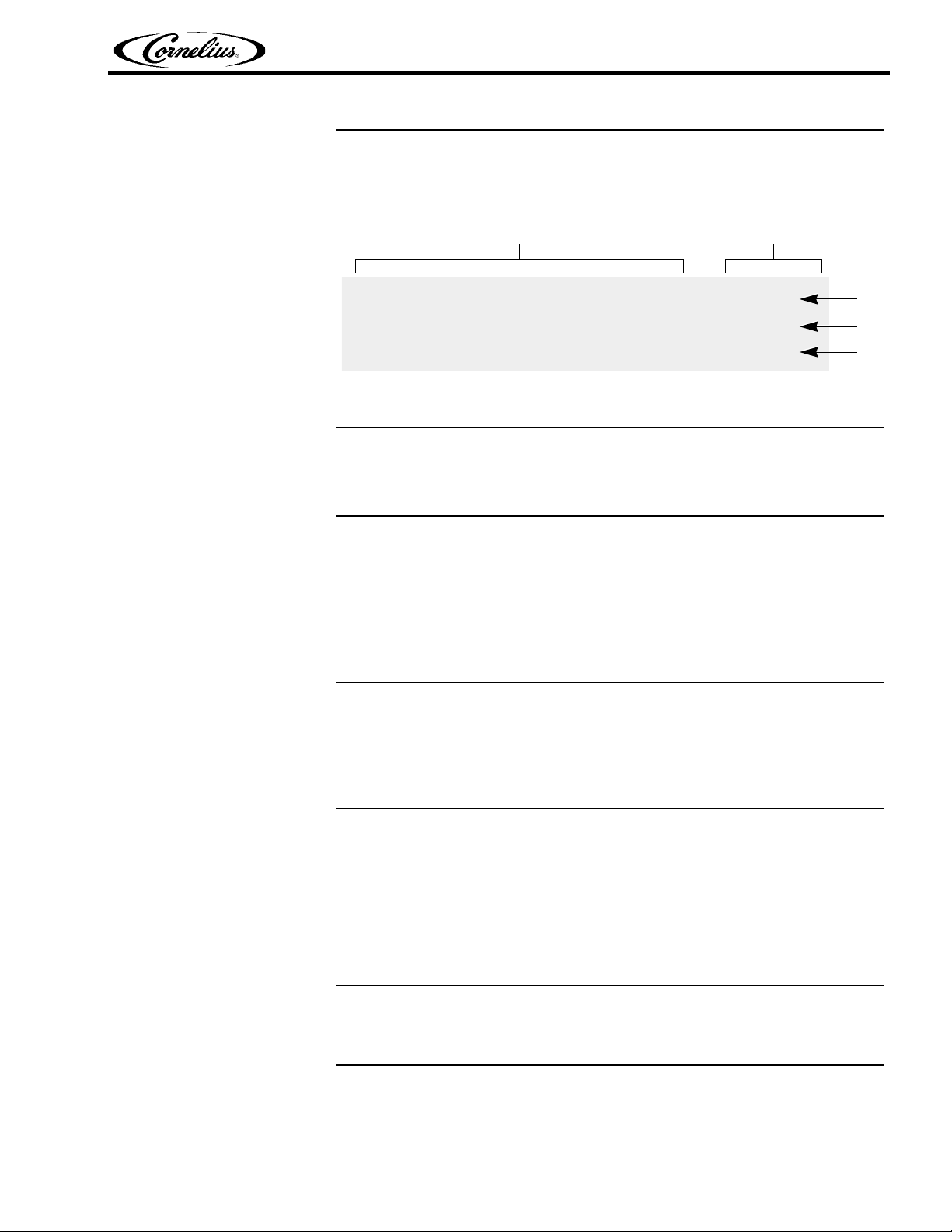
The control system is accessed using the control panel located along the top of the front
panel. The control panel contains membrane buttons and LEDs as shown in Figure 1.
Publication Number: 621058426SER - 4 - © 2011, IMI Cornelius Inc.
Signature Service Manual
Control Buttons & LEDs Status LEDs
(Green) (Red)
L1
L2
L3
Control Panel Display
The Status LEDs on the right side of the panel are used for diagnostics and troubleshooting of the unit.
Figure 1. Control Panel Display.
CONTROL PANEL BUTTON DESCRIPTIONS
The following section describes the information displayed for each control panel setting and the interactions that are controlled by that setting.
The Signature control panel is a very simple design. It allows the operator to control
the unit with the push of a button. Troubleshooting information on the unit is available
from the three LEDs on the right side of the control panel.
The error conditions are described in Table 2 on page 9.
CONTROLS AND INDICATORS
ON/OFF Button
The ON/OFF Button toggles access between the operational modes and the programming/service modes. When the ON/OFF Button is pressed; the LED above the
ON/OFF Button turns on, and the unit can then be placed into any of the 3 operational modes (Freeze, Clean, or Refrigerate). When the ON/OFF Button is pressed
while the On/Off LED is on; the LED above the ON/OFF Button turns off and the unit
can then be placed into either the programming or service mode.
This button does not turn off power to the unit.
FREEZE Button
© 2011, IMI Cornelius Inc. - 5 - Publication Number: 621058426SER
During normal operation, the FREEZE Button controls the refrigeration system of the unit.
When the FREEZE Button is On, the unit freezes the product barrel to the programmed
o
viscosity setting and maintains the hopper at less than or equal to 41
F (5o C).
Signature Service Manual
The FREEZE Button controls access to the Motor Type Selection Mode when the
unit is in the Service Mode. Pressing the FREEZE Button repeatedly steps through
the available motor types.
The FREEZE Button is also used in conjunction with the REFRIGERATE Button to
place the unit into Programming Mode.
In the Programming Mode, repeatedly pressing the FREEZE Button steps through
the coarse viscosity level settings for the product.
CLEAN Button
The CLEAN Button operates the Auger in the freeze barrel and the mixing Paddles
in the Product Bowl on top of the unit. The auger and paddles are used to agitate the
cleaning solution. Refrigeration is off in the Clean Mode.
The CLEAN Button and the REFRIGREATE Button are used together to place the
unit into the Service Mode. The system defaults to the Motor Type Mode when the
unit is placed in the Service Mode.
The Motor Calibration Mode is accessed from the Motor Type Mode by momentarily
pressing the CLEAN Button.
In the Programming Mode, repeatedly pressing the CLEAN Button steps through
the possible fine viscosity level settings for the product.
REFRIGERATE Button
PROGRAM SETTINGS
In the Component Remote Control Mode, the CLEAN Button is used as an on/off
button for each selected load.
The REFRIGERATE Button operates the unit in a temperature controlled mode. It
keeps the Product Bowl and the Barrel at a chilled temperature, but the Barrel is in a
liquid state, not frozen.
The REFRIGERATE Button is used in conjunction with the FREEZE Button to place
the unit into the Programming Mode.
The CLEAN Button and the REFRIGREATE Button are used together to place the
unit into Service Mode. In the Service Mode, pressing the REFRIGERATE Button
places the unit in the Component Remote Control Mode.
In the Component Remote Control Mode the REFRIGERATE Button is used to
select a load for testing. See “Component Remote Control” on page 31 for details on
the operation of the unit in this mode.
The Signature unit may be placed in a number of programming modes using a combination of buttons. These modes allow adjustment of viscosity, selection of motor
type, calibration of a new motor, and they allow various components to be turned on
and off for testing purposes.
Publication Number: 621058426SER - 6 - © 2011, IMI Cornelius Inc.
Signature Service Manual
The various programming modes are listed below with a description of their uses.
Programming Mode - This mode is accessed by pressing the FREEZE and
REFRIGERATE Buttons simultaneously for more than 3 seconds when the unit is
off. This allows the operator to adjust the coarse and fine viscosity settings to
change product thickness for a variety of products. The unit defaults into the coarse
viscosity indication when placed in Programming Mode.
These settings apply to product consistency in normal operation (Freeze Mode).
The consistency can be adjusted from watery to stiff, depending on the customer
preference. The higher the number (1-3), the thicker the viscosity of the product.
In addition to the coarse settings adjusted through the FREEZE Button, there is a
finer adjustment setting available by using the CLEAN Button. This has seven levels
(1-7). The higher the number, the thicker the viscosity of the product.
Factory Mode - This mode (accessed by pressing and holding the CLEAN and
REFRIGERATE Buttons simultaneously) allows the technician to select motor type,
calibrate the barrel motor and manually control the loads in the system (motors,
valves, compressor) for troubleshooting purposes.
Motor Type Mode - This mode is the default mode when the unit is placed in the Service Mode. Pressing the FREEZE Button repeatedly steps through the available
motor types.
Programming Mode
Motor Types
Type 1 - 115VAC Type 2 - 230VAC
Component Remote Control Mode - This mode (accessed by pressing the REFRIGERATE Button in the Service mode) allows the technician to independently start and
stop various system components for testing purposes.
Motor Calibration Mode - This mode (accessed by momentarily pressing the
CLEAN Button in the Service Mode) allows the technician to recalibrate a motor
when some portion of the drive system is repaired or replaced.
The Control Panel may also be used to program the unit for a variety of products and
levels of viscosity. Table 1 describes the procedure for entering and leaving Programming Mode and the steps necessary to make the adjustments allowed.
Ta b le 1 .
Step Procedure
1 The unit must be Off to enter the Programming Mode.
2
3 The FREEZE LED continues to flash indicating Programming Mode
4
5
Press and hold the FREEZE and REFRIGERATE Buttons simultaneously.
Hold for 3 seconds or until the FREEZE LED starts flashing.
The coarse viscosity level of the product is indicated by the Status LEDs
on the right side of the control panel. Refer to Figure 2 for LED display
values. Repeatedly pressing the FREEZE Button steps through the
viscosity settings (1-3).
Press the CLEAN Button, while the CLEAN LED is flashing. The fine
viscosity level is now indicated by the Status LEDs at the right side of the
control panel. Refer to Figure 2 for LED display values. Repeatedly pressing
the CLEAN Button steps through the fine viscosity settings (1-7).
© 2011, IMI Cornelius Inc. - 7 - Publication Number: 621058426SER
Signature Service Manual
MIX OUT
STATUS 2
STATUS 3
LEVEL 1
MIX OUT
STATUS 2
STATUS 3
LEVEL 2
MIX OUT
STATUS 2
STATUS 3
LEVEL 3
MIX OUT
STATUS 2
STATUS 3
LEVEL 4
MIX OUT
STATUS 2
STATUS 3
LEVEL 5
MIX OUT
STATUS 2
STATUS 3
LEVEL 6
MIX OUT
STATUS 2
STATUS 3
LEVEL 7
ON
OFF
Step Procedure
6
7
8 If this procedure is not followed, the new settings are not saved.
9 This completes the product viscosity setup procedure.
Status LEDs
The Status LEDs are located on the right side of the Control Panel, as shown in Figure 1. These LEDs are used to indicate various error conditions for the unit and the
viscosity setting for the product in the unit.
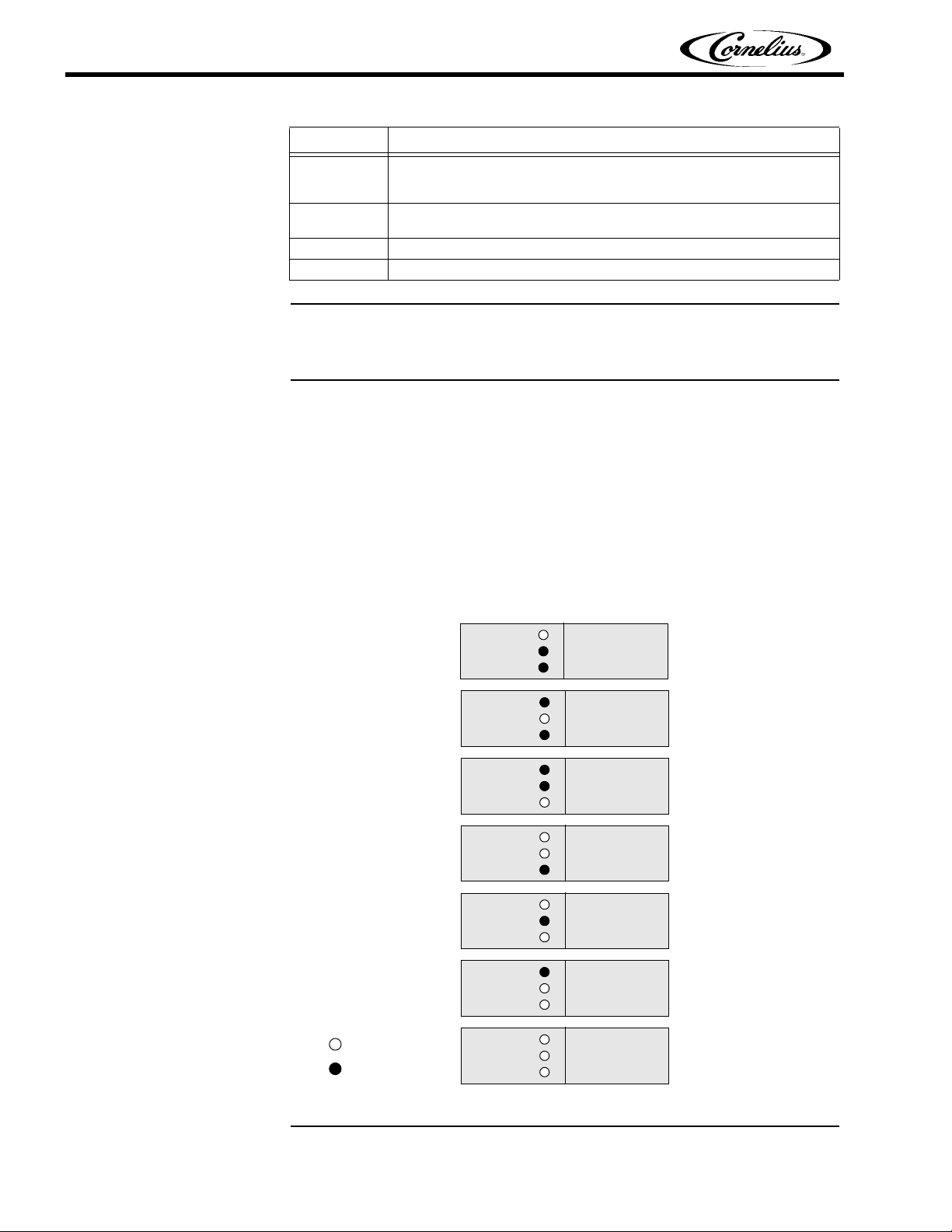
When the unit is first placed into Freeze mode, the Status LEDs show the viscosity
settings, as shown in Figure 2 (coarse for 1 second, then fine for 1 second). These
codes indicate the viscosity of the product. (i.e., if the setting of the unit is level 1, 2
then the 1st LED flashes for 1 sec. and then the 2nd LED flashes for 1 sec.)
They are also used to program the unit for the viscosity desired. There are twenty
one levels of viscosity (3 coarse settings and 7 fine settings) available for the Signature unit. Figure 2 shows how the three coarse and seven fine levels are displayed.
Ta b le 1 .
When selections are complete, press the ON/OFF Button. The four
green LEDs should illuminate, indicating that the unit is no longer in the
Programming Mode.
Press the ON/OFF Button once more to set the new viscosity settings
into memory.
Figure 2. Viscosity Setting Displays
Publication Number: 621058426SER - 8 - © 2011, IMI Cornelius Inc.
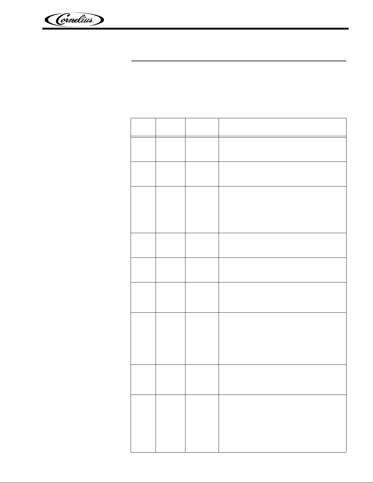
Error Conditions
Signature Service Manual
Table 2 shows the possible system errors and a description of these errors. Figure 1
on page 5 shows the locations of the LED designations on the control panel.
NOTE: FL and a number indicates that the LED is flashing, L and a
number indicates that the LED is continuously on.
Table 2.
Display
Priority
Display
Output
1
2
3L1 & FL3
4 FL1 & FL3 Barrel TCO
5 L1 & L3
6 FL1 & L3
7FL1 & FL2
8 L1 & L2
9 L3 Motor Drive
FL2 &
FL3
L1, L2 &
L3
Error Description
Corrupted
Data
Stuck
Keypad
Motor
Calibration
Machine
Disable
AC Relay
Open
Hopper
Refrigeration Error
Barrel
Refrigeration Error
Occurs when the system reads the user settings
from EEPROM and it has become corrupted. The
unit shuts down and the EEPROM must be reprogrammed.
Occurs when any one of the keypad buttons is not
functional anymore. This error can be detected at
start-up or if a continuous key press is detected for
more than 1 minute during any run mode.
Occurs only in the Service Mode when calibration
value is outside the +/-10% window from the factory reference value. Once started, the calibration
process requires 10 min. to complete. Any interruptions prevent the unit from performing a motor
calibration. The user can clear the error from the
front panel. (Press and Hold ON/OFF Button for 3
seconds).
Occurs when any of the thermistors measure more
than 120°F for 10 seconds and the unit is in either
the REFRIGERATE or FREEZE Mode. It can only
be cleared by power cycling the unit.
This error occurs when the faceplate switch is deactivated. Motor power is not available (also see next
error). The unit is disabled until the faceplate is
properly installed.
This error occurs when the motor controller does
not detect voltage available for the motors but the
faceplate is in place (can be refrigeration pressure
switch or related circuit element). It can only be
cleared by power cycling the unit.
This error is triggered when hopper temperature
does not pull down in a specified time when in
FREEZE or REFRIGERATE Mode. (Cut-in Temp +
13° F within 3 hrs.); it is assumed that the hopper
evaporator is malfunctioning. (This error timer is not
interrupted when the barrel takes refrigeration priority). The error timer is cleared when the hopper
goes into IDLE state. The error itself can only be
cleared by power cycling the unit.
This error is triggered when the barrel has been in
FREEZE or REFRIGERATE Mode (viscosity not
reached) for more than 40 min. Every handle activation (product dispense) resets the error timer. This
error can only be cleared by power cycling the unit.
This error can be caused by two states: it can occur
when the barrel motor command is on, but no motor
current is detected, such as if the motor is disconnected. This case can be cleared from the front
panel, which should be tried first (Turn unit OFF for
3 sec., then ON). However, it also occurs if the barrel motor is turned off but motor current is still
detected; in this case, the error display will clear via
the front panel, but reoccurs IMMEDIATELY. Unit
must be power cycled to clear it.
© 2011, IMI Cornelius Inc. - 9 - Publication Number: 621058426SER
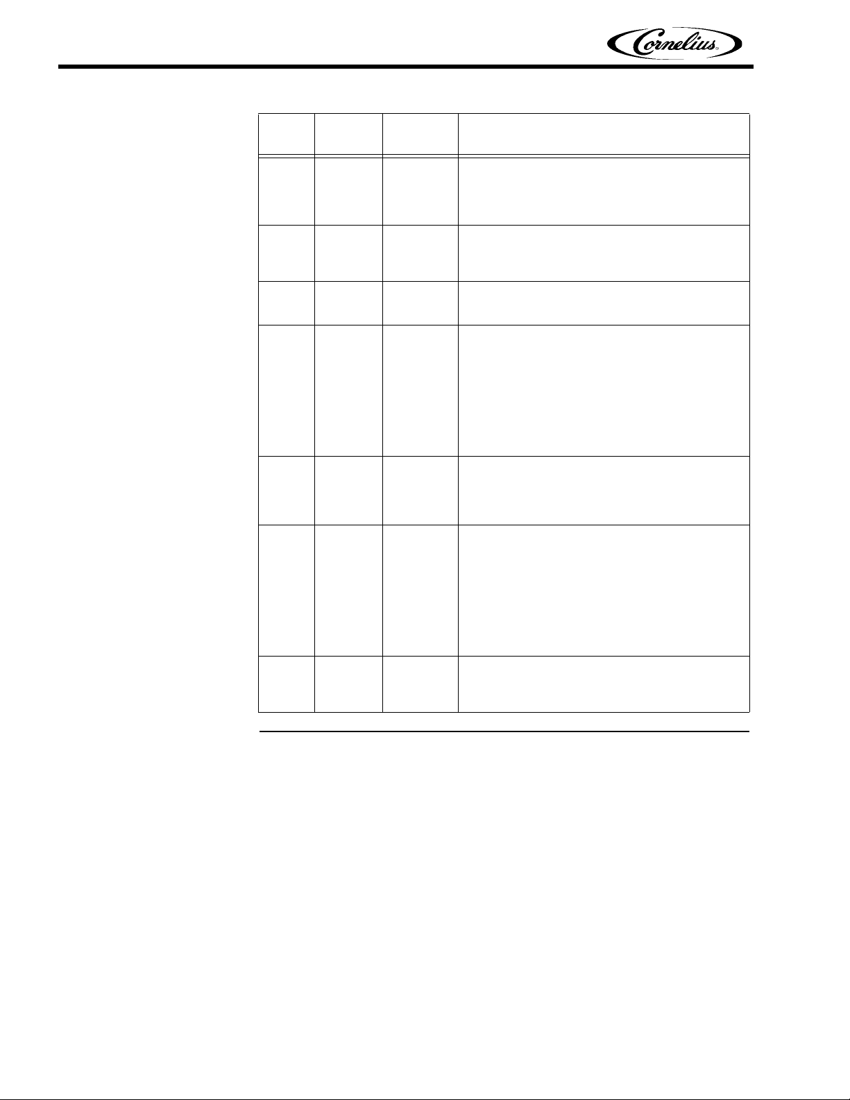
Signature Service Manual
Display
Priority
10 L2
11 FL2 No Handle
12 L2 & L3
FL1, FL2 &
13
FL3
14 FL3 Motor Stall
15 FL1 No Product
16 L1
Display
Output
Table 2.
Error Description
This error is triggered when any of the 3 thermistors
Thermistor
Error
Communication Error
Voltage
Error
Low
Product
are detected open for more than 30 seconds. The
error timer resets when all the thermistors read
"normal". This error can only be cleared by power
cycling the unit.
Occurs when the handle is open for a period of 1
minute while the system is in Freeze or Refrigerate
Mode. The error auto resets if the handle is
detected again.
This error occurs when no communication packets
are detected for a period of 10 seconds. This error
clears when communication is reestablished.
This error occurs when line voltage is above or
below normal functional limits for more than 30 sec.
(It can also be triggered when the wrong motor type
is selected in Service mode.) Limits are determined
based on nominal (115V /230V) line voltage +10%
up and -15% down. Error can auto reset if voltage is
reestablished within normal limits for at least 30
sec. User can clear the error from the front panel.
by pressing and holding the ON/OFF Button for 3
seconds.
This error occurs when the control board reports a
stall condition on the motor. The error is detected
when the unit is in any run mode. The error can be
cleared from the front panel by pressing and holding
the ON/OFF Button for 3 seconds.
No product is an error that can be detected only in
mix out condition. Error is triggered if the dispense
lever has been activated for a cumulative time of 2
min. This error prevents the user from accessing
FREEZE or REFRIGERATE Mode because it is
assumed that there is no more product in the barrel
to be served. However, the user can access CLEAN
Mode. The error automatically clears if the unit is in
ON Mode and the hopper is refilled with product.
This restores access to all unit modes.
This error occurs when low product level is detected
in the hopper; the system goes into MIXOUT Mode.
The error automatically clears if more product is
added to the hopper.
Publication Number: 621058426SER - 10 - © 2011, IMI Cornelius Inc.
Signature Service Manual
STARTING THE UNIT
OPERATION
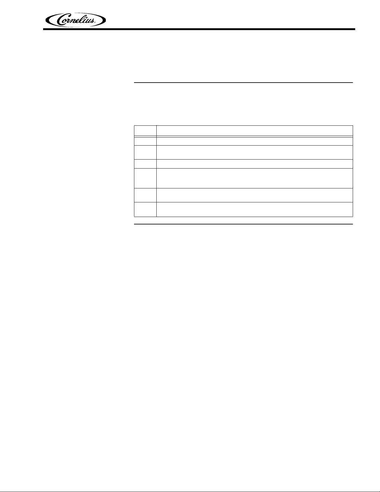
Table 3 describes the basic procedure for starting the Signature unit. Refer to the
Operator’s Manual (P/N 621058426OPR) for details on daily operation and operator
maintenance of the unit.
Table 3.
Step Action
1. Remove the Bowl Cover Lid and fill the Product Bowl on top of the unit with product.
2. Allow the barrel to fill with product and insert the air/mix tube into the bowl (if
dairy product is being used).
3. Press the ON/OFF Button on the control panel to activate the control panel.
4. Press the FREEZE Button to start chilling the product in the unit. The unit
automatically starts to chill down the product in the barrel and the mixing
blades in the Product Bowl on top of the unit start to spin.
5. Wait 10 to 15 minutes or until the Freeze LED stops flashing before dispensing
the product.
6. Product is ready to serve from the barrel, however, the unit continues to run
until the temperature of the Product Bowl is satisfied.
© 2011, IMI Cornelius Inc. - 11 - Publication Number: 621058426SER
Signature Service Manual
CAUTION:
!
CAUTION:
!
PREVENTATIVE MAINTENANCE
SUMMARY
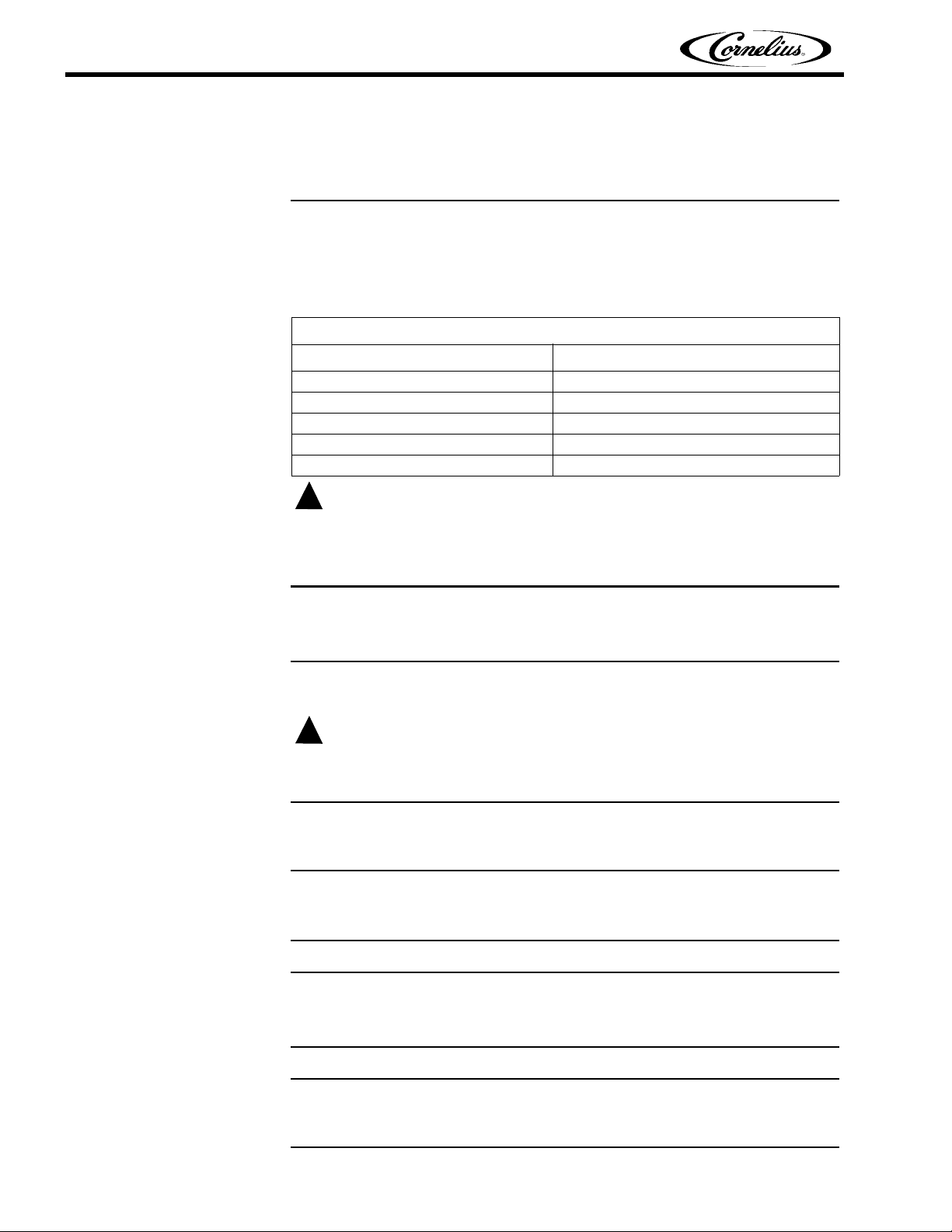
Normal equipment maintenance procedures and intervals are listed in Table 4. It is
recommended that preventative maintenance procedures be performed every six
(6) months. This procedure should include all of the maintenance items described
in Table 4 and the following sections.
Maintenance Procedure Frequency of Maintenance
Sanitize Unit Daily (especially w/dairy products)
Cl ean A ir Fil ter Monthly or more often, as necessary (See Table 13)
Clean Condenser Coil Every six months or as necessary
Change Scraper Blades Every six months
Check for Leaks Every six months
Table 4.
Preventative Maintenance Summary
Only trained and certified electrical, plumbing and refrigeration technicians should
service this unit. ALL WIRING AND PLUMBING MUST CONFORM TO
NATIONAL AND LOCAL CODES.
DAILY MAINTENANCE
On a daily basis, clean all external surfaces with a mild soap solution and rinse
with potable water. D.ry all external surfaces with a clean soft cloth.
Avoid the use of abrasive cleaners and chlorine based solutions, which can damage
the finish. If desired, small parts may be cleaned in a dishwasher.
Cleaning and Sanitizing Procedure
Under normal operating conditions, the unit must be sanitized on a daily basis,
specially if dairy products are being used in the unit.
Supplies
Warm water, house hold dish washing detergent [3.0 oz. (89 ml) in 3.0 gallons (11.4
o
liters) of warm water solution at 90-100
F (32-38oC)] or KAY-5 sanitizer (100ppm).
Tools
Draining bucket, brushes, magnet removal tool, spray bottle for sanitizer and food
grade lubricant.
Publication Number: 621058426SER - 12 - © 2011, IMI Cornelius Inc.
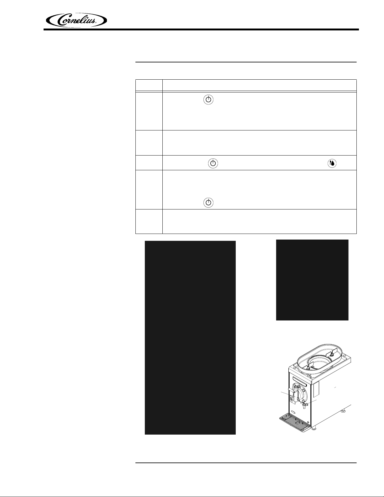
Draining the Unit
Figure 5.
Figure 4.
22 ffoorr 11 DDiissppeennssee
NNoozzzzllee
DDiissppeennssiinngg
VVaallvvee
Figure 3.
Signature Service Manual
Table 5.
Step Procedure
Press ON/OFF Button to turn off the unit.
NOTE: It is recommended that you shut the unit off as far ahead of
1
cleaning as possible to allow the product in the barrel to
thaw for easier removal.
NOTE: Air tube and blade sweepers are only used for dairy products.
2
Remove the Bowl Lid Cover and Air Tube. Place the Air Tube in a parts bin to be
cleaned later. Replace the Bowl Lid Cover. See Figure 3.
3
Press the ON/OFF Button to turn the unit ON and push the CLEAN Button.
Place an empty bucket under the Product Dispense Valve and move dispense
handle to the right (open position, shown in Figure 4) and drain as much liquid
as possible. Allow the last of the product to drain, then close the dispenser
4
valve by turning the dispense handle all the way to the left.
Press ON/OFF Button to turn OFF the unit.
NOTE: Skip this step if the unit does not have the 2 for 1 feature.
5
Place the bucket under the 2 for 1 Dispense Nozzle, pull the handle and
allow the product to drain until the line is empty, see Figure 5.
© 2011, IMI Cornelius Inc. - 13 - Publication Number: 621058426SER
 Loading...