

Cornelius Remcor 620037007, Remcor 620043506, Remcor 620701901, Remcor 620919507, Remcor 629087903 Installation Instructions Manual
...Page 1
DF/ED175-8V “K” Style Lid Kit Installation Instructions
!
WARNING:
!
WARNING:
!
WARNING:
INSTALLATION INSTRUCTIONS
FOR DF/ED175-8V “K” STYLE LID KIT
(P/N 629087903 (GRAY) AND 629087905 (BLACK)
This “K” style kit applies to the following ice makers:
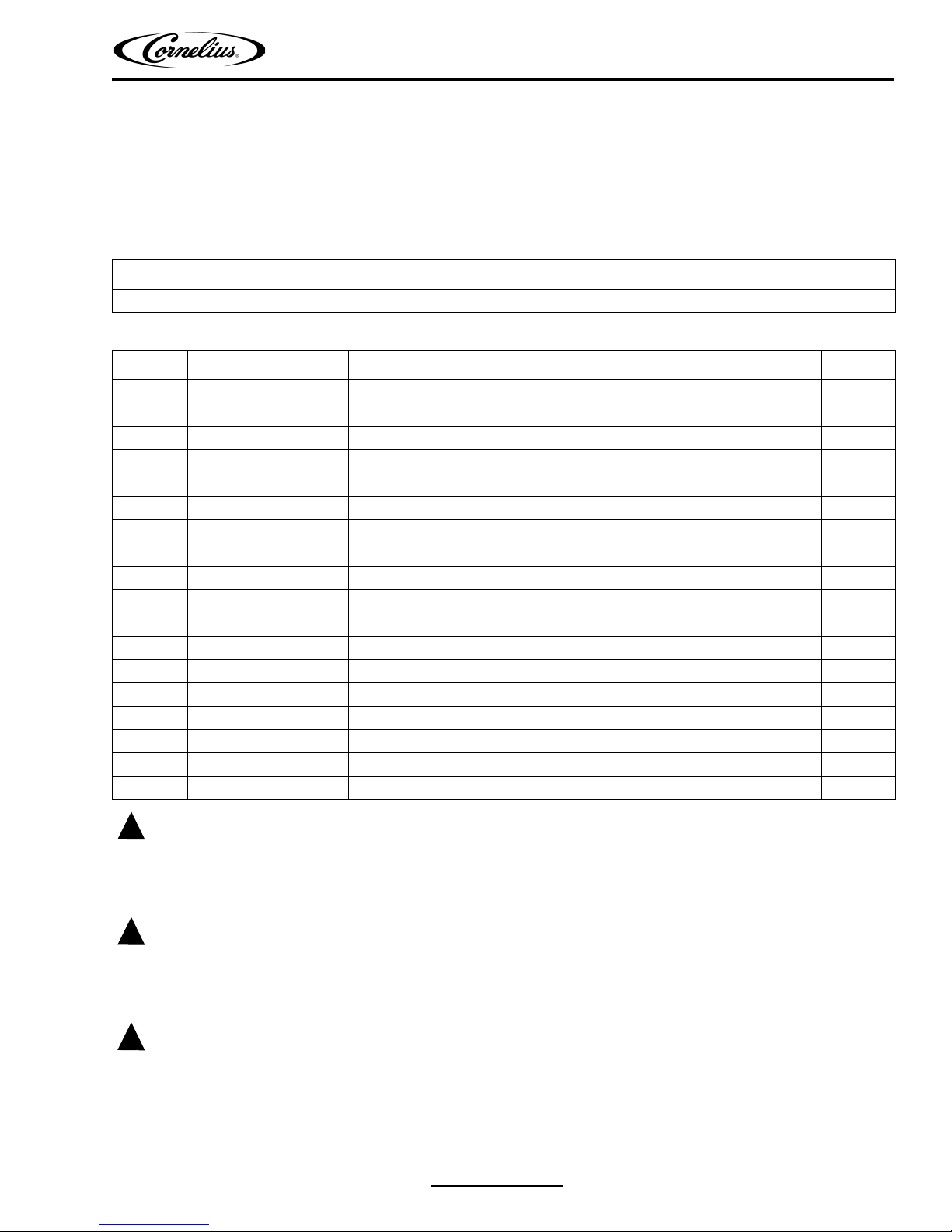
Table 1. Applicable Models
Ice Maker Width
AC and WC Cornelius 322/522 22”
Table 2. Loose Shipped Parts
Item No. Part No. Name Qty.
1 620043511 Cover, Gray 1
620043512 Cover, Black 1
2 620043506 Lid Assembly 1
3 22127 Bracket 2
4 70217 Screw, No. 8 12
5 50904 RTV 1
6 90221 Label 1
7 620919507 Installation Instruction 1
8 620701902 Acorn Nut, Nylon, 8-32 2
9 620701901 Sealing Washer 2
10 620037007 Ice Baffle, DF/ED150 1
11 621701903 Nylon Washer, #8 2
12 620505804 Insulation Strip 1
13 50456 Nylon Clamp, 1/4-in. 2
14 70171 Screw, Phillips Hd; SS, 8-32 X 3/8 in. 2
15 50377 Nylon Clamp, 1/8-in. 2
16 50309 Vinyl Tubing, 1/8-in. Dia. by 1/2-in. Long 25
17 631500000 Bin Stat Kit 1
Disconnect power to the unit before installing the adaptor following all lockout/tag out procedures established by the
user. Verify that all the power is off to the unit before performing any work.
Failure to comply could result in serious injury, death or damage to the equipment.
All ice baffle plates and bin stats, if included or recommended in this kit, must be installed as directed in this manual or
the equipment manufacturer’s instructions.
Failure to comply could result in serious injury, death or damage to the equipment.
All of the attachment screws and plates must be installed as directed in this manual.
Failure to comply could result in serious injury, death or damage to the equipment.
1. Unpack the kit.
2. Place insulation strip (Item 12) over studs on the baffle and Insert baffle assembly into the adapter lid.
Release Date: November 11, 2010 www.cornelius.com Revision: B
© 2000-2010, IMI Cornelius Inc. - 1 - Publication Number: 620919507
Page 2

DF/ED175-8V “K” Style Lid Kit Installation Instructions
3. Place two (2) sealing cap washers (item 9) over studs and two (2) nylon washers (item11), then fasten in place
with two (2) acorn nuts (item 8).
4. Set ice maker lid on the top of the dispenser.
5. Using the slotted holes in the lid as a template, drill four (4) 0.140” diameter (9/64”) holes at the bottom of the slots
(see Detail A of Figure 1). Use extreme care not to drill into the hopper. Fasten the lid to the dispenser with four
(4) #8 sheet metal screws, two on each side.
6. Seal the ice maker to the top of the dispenser as follows:
A. Run beads of RTV around the opening in the lid and inside of the perimeter of the ice maker outline so
that the ice maker will set on the RTV.
B. Set the ice maker onto the lid and position it as required.
C. Wipe away the excess RTV.
7. Drill 9/64” diameter holes into the ice maker cabinet using the bracket as a template. Use extreme care not to drill
into any ice maker components (condenser, tubing, etc.). Secure the brackets using the screws provided.
8. Mount bin stat kit (item 17) as instructed except for the bin stat capillary tube mounting.
9. Pull 32” of capillary tube out of bottom of the ice maker. Slit and place vinyl tubing (item 16) over the capillary tube
leaving 6” of bare capillary tube exposed between capillary “S” bend and vinyl tubing.
10. Assemble two (2) nylon clamps (item 15) to the back side of the ice baffle (item 10) with two (2) screws (item 14)
and acorn nuts (item 8).
Do not overtighten.
11. Route capillary tube around baffle as shown in Figure 2 and Figure 3.
12. Position two (2) nylon clamps (item 15) on studs of ice baffle (item 10) and two (2) nylon washers (item 11) on
studs as shown.
13. Place plastic insulation strip over the studs and insert baffle assembly into the bladder lid.
14. Place two (2) sealing washers (item 9) over studs and fasten in place with four (2) acorn nuts (item 8).
15. Route and form capillary as shown in Figure 2 and Figure 3. Tighten two (2) plastic clamps (8-32 X 3/8” screws)
to hold capillary tube in place.
16. Turn bin stat adjustment screw to the right (clockwise) until it stops, then, turn adjustment screw to the left (counterclockwise) 1/8 turn. Verify the bin stat is working by holding ice on the bare capillary tube. The bin stat allows
the ice machine cycle to complete and harvest ice, then the machine shuts down.
17. If the acorn nuts interfere with the positioning of the plastic manual fill cover, it may be necessary to make small
notches in the cover to clear the acorn nuts.
NOTE: Bin thermostat must not interfere with the agitator rotation.
Publication Number: 620919507 - 2 - © 2000-2010, IMI Cornelius Inc.
Page 3

DF/ED175-8V “K” Style Lid Kit Installation Instructions
© 2000-2010, IMI Cornelius Inc. - 3 - Publication Number: 620919507
Figure 1. Dispenser Assembly
Page 4

DF/ED175-8V “K” Style Lid Kit Installation Instructions
Publication Number: 620919507 - 4 - © 2000-2010, IMI Cornelius Inc.
Figure 2. Baffle
Page 5

DF/ED175-8V “K” Style Lid Kit Installation Instructions
© 2000-2010, IMI Cornelius Inc. - 5 - Publication Number: 620919507
Figure 3. Capillary Tube Location
 Loading...