

Page 1
SPECIALTY BEVERAGE DISPENSER
NITROPRO MINI
Service and Preventative Maintenance Manual
Release Date: 2/15/19
Publication Number: 548000106SER
Revision Date: 2/15/19
Revision: Rev. 2.0 Model: CNB Mini
Visit web site http://cornelius-usa.com and create an account for all your literature needs.
Page 2

The products, technical information, and instructions contained in this manual are subject to change without notice. These
RECYCLE
instructions are not intended to cover all details or variations of the equipment, nor to provide for every possible contingency
in the installation, operation or maintenance of this equipment. This manual assumes that the person(s) working on the equip
ment have been trained and are skilled in working with electrical, plumbing, pneumatic, and mechanical equipment. It is
assumed that appropriate safety precautions are taken and that all local safety and construction requirements are being met,
in addition to the information contained in this manual.
This Product is warranted only as provided in Cornelius’ Commercial Warranty applicable to this Product and is subject to all of
the restrictions and limitations contained in the Commercial Warranty.
Cornelius will not be responsible for any repair, replacement or other service required by or loss or damage resulting from any
of the following occurrences, including but not limited to, (1) other than normal and proper use and normal service conditions
with respect to the Product, (2) improper voltage, (3) inadequate wiring, (4) abuse, (5) accident, (6) alteration, (7) misuse, (8)
neglect, (9) unauthorized repair or the failure to utilize suitably qualified and trained persons to perform service and/or repair
of the Product, (10) improper cleaning, (11) failure to follow installation, operating, cleaning or maintenance instructions, (12)
use of “non‐authorized” parts (i.e., parts that are not 100% compatible with the Product) which use voids the entire warranty,
(13) Product parts in contact with water or the product dispensed which are adversely impacted by changes in liquid scale or
chemical composition.
Contact Information:
To inquire about current revisions of this and other documentation or for assistance with any Cornelius product contact:
www.cornelius.com
800-238-3600
Trademarks and Copyrights:
This document contains proprietary information and it may not be reproduced in any way without permission from Cornelius.
‐
This document contains the original instructions for the unit described.
CORNELIUS INC
101 Regency Drive
Glendale Heights, IL
Tel: + 1 800‐238‐3600
Printed in U.S.A.
Correct Disposal of this Product
This marking indicates that this product should not be disposed with other household wastes throughout the EU. To prevent
possible harm to the environment or human health from uncontrolled waste disposal, recycle it responsibly to promote the
sustainable reuse of material resources. To return your used device, please use the return and collection systems or contact
the retailer where the product was purchased. They can take this product for environmental safe recycling.
Page 3

Table of Contents
1.0 SAFETY 1
2.0 OVERVIEW AND REQUIRED TOOLS 3
2.1 Nitropro Functions & Specifications 3
2.2 Key Components 4
2.3 Required Tools 6
3.0 SYSTEM OPERATION 7
3.1 Facility Supplies 7
3.2 Operating Processes 8
3.3 Component Functions
3.3.1 Tap Handles 10
3.3.2 Product Concentrate Pump 10
3.3.3 Water Inlet Solenoid 11
3.3.4 Air Compressor & Storage 11
3.3.5 Mixing-Infusion Manifold & Check Valves 11
3.3.6 Dispense Manifold 12
3.3.8 Mixing-Dispensing Assembly 12
3.3.9 Ice Bank Chilling System 13
3.3.10 Front-Door Control Switches 14
4.0 PREVENTATIVE MAINTENANCE 15
4.1 Overview 15
4.2 Maintenance Schedule 15
4.3 Annual Maintenance 15
4.3.1 Refrigeration Condenser & Cabinet Fan Cleaning 15
4.3.2 Ice Bank Level Check 15
4.3.3 Product Pump Mix-Ratio Verification 16
4.3.3.1 Measuring TDS (Total Dissolved Solids) 16
4.3.4 Components Visual Inspection 18
4.3.5 Ice-Bank Sensor & Agitator Check 18
4.3.6 Concentrate-Pump Hose Replacement 19
Page 4

Table of Contents
5.0 TROUBLESHOOTING 20
Table 5-1 - Systems-Level Troubleshooting 20
Table 5-2 - Drink-Quality Troubleshooting 21
Table 5-3 - Compressed Air & Infusion Troubleshooting 22
Table 5-4 - Dispensing-Function Troubleshooting 23
5.1 Air-Compressor Pressure Verification 24
6.0 COMPONENT REPLACEMENT 25
6.1 Safety Precautions 25
6.3 Access Panel Removal 25
6.3 Main PCB 27
6.4 Mixing-Dispensing Assembly Components 28
6.4.1 Air Pressure Regulator 28
6.4.2 Mixing - Infusion Manifold 29
6.4.3 Dispense Manifold 29
6.4.4 Concentrate Pump 30
6.5 Air Compressor 30
6.5.1 Compressor Air Filter Replacement 30
6.6 Water Inlet Solenoid 31
6.7 Power Supply (24Vdc) 31
6.8 Merchandiser LED Back-Lighting Panel 32
6.9 Ice Bank 32
6.9.1 Ice Sensor Probe 32
6.9.2 Agitator Motor 33
6.9.3 Ice Bank Controller 34
6.9.4 Refrigeration Components 35
6.10 Tap Microswitches 35
APPENDIX A - SYSTEM DRAWINGS 37
Page 5

Nitropro Mini Service Manual
!
!
!
!
1.0 SAFETY INSTRUCTIONS
Safety Overview
• Read and follow ALL SAFETY INSTRUCTIONS in this manual and any warning/caution labels on the
unit (decals, labels or laminated cards).
• Read and understand ALL applicable OSHA (Occupational Safety and Health Administration) safety
regulations before operating this unit.
Types of Alerts
!
DANGER: Indicates an immediate hazardous situation which if not avoided WILL result in
serious injury, death or equipment damage.
!
WARNING: Indicates a potentially hazardous situation which, if not avoided, COULD result in
serious injury, death, or equipment damage.
!
CAUTION: Indicates a potentially hazardous situation which, if not avoided, MAY result in
minor or moderate injury or equipment damage.
SAFETY TIPS
• Carefully read and follow all safety messages in this manual and safety labels on the unit.
• Keep safety labels in good condition and replace missing or damaged ones.
• Do not let anyone operate the unit without proper training. This appliance is not intended for use
by untrained or unauthorized persons without supervision.
• Maintain the unit in proper working condition and do not allow any unauthorized modifications.
NOTE: The dispenser is not designed for a wash-down environment and MUST NOT be placed in
an area where a water jet could be used.
QUALIFIED SERVICE PERSONNEL
WARNING:
Only trained and certified electrical, plumbing and refrigeration technicians should service this unit.
ALL WIRING AND PLUMBING MUST CONFORM TO NATIONAL AND LOCAL CODES. FAILURE TO COMPLYCOULD RESULT IN SERIOUS INJURY, DEATH OR EQUIPMENT DAMAGE. IF THE SUPPLY CORD IS DAMAGED,
IT MUST BE REPLACED BY THE MANUFACTURER, ITS SERVICE AGENT OR SIMILARLY QUALIFIED PERSONS
IN ORDER TO AVOID A HAZARD.
© 2019, Cornelius Inc. All Rights Reserved - 1 - Publication Number: 548000106SER
Page 6

Nitropro Mini Service Manual
!
!
!
!
1.0 SAFETY INSTRUCTIONS (CONT.)
SAFETY PRECAUTIONS
This unit has been specifically designed to provide protection against personal injury. To ensure continued protection observe the following:
DANGER:
Disconnect power to the unit before servicing while following all lock out/tag out procedures established by the user. Verify power is off to the unit before any work is performed.
FAILURE TO DISCONNECT THE POWER COULD RESULT IN SERIOUS INJURY, DEATH OR EQUIPMENT
DAMAGE.
CAUTION:
Always be sure to keep area around the unit clean and free of clutter. Failure to keep this area clean may
result in injury or equipment damage.
DO NOT STORE EXPLOSIVE SUBSTANCES SUCH AS AEROSOL CANS WITH A FLAMMABLE PROPELLANT IN
THIS APPLIANCE.
UNTRAINED AND UNAUTHORIZED INDIVIDUALS SHALL NOT OPERATE THE APPLIANCE OR PERFORM
ANY CLEANING OR USER-MAINTENANCE PROCEDURES.
SHIPPING AND STORAGE
CAUTION:
Before shipping, storing, or relocating the unit, the unit must be sanitized and all sanitizing solution
must be drained from the system. A freezing ambient environment will cause residual sanitizing solution
or water remaining inside the unit to freeze resulting in damage to internal components.
MOUNTING IN OR ON A COUNTER
DANGER:
When installing the unit in or on a counter top, the counter must be able to support a weight in excess of
140 lbs. (63.5 kg.) to insure adequate support for the unit.
FAILURE TO COMPLY COULD RESULT IN SERIOUS INJURY, DEATH OR EQUIPMENT DAMAGE.
THE APPLIANCE MUST BE ORIENTED IN A VERTICAL POSITION.
Publication Number: 548000106SER - 2 - © 2019, Cornelius Inc. All Rights Reserved
Page 7
2.0 OVERVIEW AND REQUIRED TOOLS
2.1 Nitropro Functions & Specifications
The Nitropro Mini dispenses still or air-injected,
chilled Nitro coffee at the pull of a tap handle.
Opening a tap automatically engages the product
mixing pump (as well as the air pump for the
injected-coffee selection). The dispensing unit
requires facility electrical and water inputs; Nitro
infusion gas is generated within the unit.
• Coffee syrup from a product container is automatically mixed with water at the selected
ratio (with mix ratios user-selectable via a DIP
switch on the main control PCB)
• Nitro coffee is created via its dispensing circuit
including a gas-infusion (air-injection) manifold prior to the tap (dispensing) valve
• Metering of the product concentrate is performed by a servo-driven, peristaltic pump
• Water inlet rate is fixed and controlled by an
inlet solenoid valve assembly that also provides pressure limiting and flow control
• Chilling of the product cabinet and mix water
is performed by an automatically-controlled
ice bank at the base of the enclosure
Water Supply Pressure
Water Supply
Flow Rate
Water Temperature 40 - 90° F. (4.4 - 32.2° C)
Water Inlet Size
Table 2-5 - General | Dimensions | Weight
Unit Height 34.05 in. (86.5 cm)
Unit Width 10.44 in. (26.5 cm)
Unit Depth 24.47 in. (62.2 cm)
Clearance
Requirements
Unit Weight (Dry) 120 lbs (54.4 kg)
Operating Weight 185 lbs (84.0 kg)
Ambient Operating
Temperature
Nitropro Mini Service Manual
Table 2-4 - Water Requirements
35 psig (241 kPa) Min.
90 psig (621 kPa) Max.
(if >90 psi, install external pressure regulator, set @ 50 psi)
3 fl. oz. (88.7 ml) per
second, minimum
3/8 in. (0.95 cm) SAE male flare
fitting on dispenser
Back: 4” (10.16 cm)
Top: 12” (30.48 cm)
Sides: 4” (10.16 cm)
50 to 90 °F (10 to 32 °C)
Table 2-1 - Electrical Specifications
Models
Mini 115 5 1 60
CNB
CNB
Mini 230 2 1 50
VAC Amps Ph Hz
Ice Bank Capacity 7-8 lbs. (3.2-3.6 kg.)
Temp. Pull Down Time 3 hours at 75 °F (24 °C)
Table 2-6 - Ice Bank Specifications
Table 2-2 - Refrigerant Type
Refrigerant
Oz Grams Type
5.64 160 R-134a
Table 2-3 - Refrigeration Nameplate Values
Pressure psi (kPa) [bar]
High
side Low side
315 (2171.9) [21.7
© 2019, Cornelius Inc. All Rights Reserved - 3 - Publication Number: 548000106SER
] 140 (965.3) [9.7]
Page 8
Nitropro Mini Service Manual
Figure 2-1 - Front LED-Backed Merchandiser Removal
2.0 BREWER OVERVIEW AND REQUIRED TOOLS (Cont.)
2.2 Key Components
The Nitropro Mini consists of these main controls
and components (refer to Figs. 2-1 and 2.2).
Dispensing Taps (for Still & Nitro Coffee)
Allow coffee dispensing. Pulling of tap
handle triggers switch that activates outlet
solenoid valve (in dispense manifold); also
turns on water inlet solenoid valve and
concentrate pump to initiate flow.
Ice Bank (Water Reservoir and Refrig. Unit)
Water/ice-filled reservoir for chiller lines.
Includes controller to manage refrigeration
compressor, bath agitator, circulation pump
and temperature/ice sensor.
Air Compressor & Storage Chamber
Provides air to the gas-infusion manifold.
Stores compressed air to support high drink
volumes. The compressor is independent
and is activated by the storage-chamber
pressure switch. Storage outlet routes to a
pressure regulator prior to entering the
infusion manifold.
System Controller Board (Main PCB)
Manages system events and device
interactions. Includes adjustable DIP switch
for concentrate-pump ratio selection. Also
includes PCB switches for fine-tuning the
ratio selection.
24Vdc Power Supply
Provides power to Main PCB and the air
compressor.
Concentrate Pump
Meters input of coffee product from BIB
(Bag In Box) to mixing manifold. Peristaltic
pump, servo-motor driven.
Product-Mixing & Gas-Infusion Manifold
Interconnected plastic blocks with check
valves and a mixing chamber for mixing, airinjecting and routing of coffee concentrate,
water and air to the dispense manifolds.
Three check valves control flow routing by
preventing backflow.
Dispense Manifolds
Tap-handle activated, outlet solenoid valve.
Outlet valve allows product dispensing.
Water-Inlet Solenoid Valve/Regulator
Solenoid valve allows water inlet.
Regulator limits inlet pressure & flow rate.
Publication Number: 548000106SER - 4 - © 2019, Cornelius Inc. All Rights Reserved
Page 9

Nitropro Mini Service Manual
2.0 BREWER OVERVIEW AND REQUIRED TOOLS (Cont.)
2.2 Key Components (Cont.)
Figure 2-2 - Main Components
© 2019, Cornelius Inc. All Rights Reserved - 5 - Publication Number: 548000106SER
Page 10

Nitropro Mini Service Manual
2.0 BREWER OVERVIEW AND REQUIRED TOOLS (Cont.)
2.3 Required Tools
These tools are required for conducting the various procedures in this manual. You may find it
helpful to review the Troubleshooting and Component Replacement sections to determine what
additional tools you might prefer to include.
HAND TOOLS
ELECTRICAL TOOLS
Multimeter - Digital VOM
1000V/10A ac/dc, milliohm to megohm, millivolt,
auto-ranging, ±2.5% +1 digit accuracy
Wrenches - SAE Open-end or Combination
(1/4” through 7/8”)
Wrenches - Adjustable
(2” x 6”- 8” Length, Crescent)
Nut Driver Set - SAE
Pliers - Adjustable
Channel-Lock/Knipex-style
Pliers - Needlenose
Flat Screwdriver
3/16”
Phillips Screwdrivers
#2 & #0 (6” Length)
#2 Stubby or Flex-shaft
Diagonal Cutting Pliers
Pick Set - Dental Type
Magnetic Pickup Wand
Temp erat ure Mete r & P rob e
±2.5% +1 digit accuracy
Cordless Drill or Screwdriver
With Screwdriver Bits / Nut Drivers
Flashlight
Portable Vacuum Cleaner
With hose and crevice tool
SUPPLIES
O-Ring Lubricant/Sealant Food-Grade Silicone
Dow Corning Molykote 111 or equiv.
Solvent - Nonflammable
Tefl on T hre ad- sea lin g Ta pe
Lint-free Cloth Rags
Cleaning Brushes
Bristle and Wire
Air Pressure Gauge
Capable of 100 psi (689 kPa)
with high-pressure hose and
1/4”push-connect fitting
Hose-Clamp Crimping/Cutting Tool
Oetiker HIP 2800 Es
Publication Number: 548000106SER - 6 - © 2019, Cornelius Inc. All Rights Reserved
Page 11
3.0 SYSTEM OPERATION
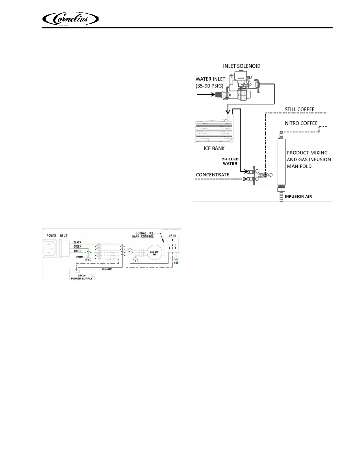
Figure 3-1 - Power Input
Figure 3-2 - Water Input
This section describes how the Nitropro Mini dispenser operates. By grasping the details of the
operating process for still and Nitro coffee dispensing, you will have the knowledge to detect
many of the common malfunctions.
3.1 Facility Supplies
Electrical: Depending on model and application,
the unit operates from either 115Vac or 230Vac
that enters the unit through a back-panel cord
socket, as shown in Fig 3-1. Input AC power is supplied to the ice bank controller (which manages
the refrigeration compressor and the ice-bath agitator motor). AC power is also routed to the
24Vdc power supply which provides power to the
Main PCB and the air pump. The Main PCB then
provides 24V power to the remainder of the DC
components.
Nitropro Mini Service Manual
Water: Store water enters the unit through a rear
inlet solenoid valve within the pressure range
indicated in Figure 3-2. The inlet solenoid valve
activates when a dispensing tap is pulled. The
inlet solenoid assembly also provides input pressure control [29 psi (200 kPa) - fixed] and flow-rate
limiting within the range of 1 to 1.25 fluid ounces
(29.6 to 37 ml) per second.
Inlet water is first routed to the ice bank for chilling and then is supplied to the mixing-infusion
manifold.
© 2019, Cornelius Inc. All Rights Reserved - 7 - Publication Number: 548000106SER
Page 12
Nitropro Mini Service Manual
1
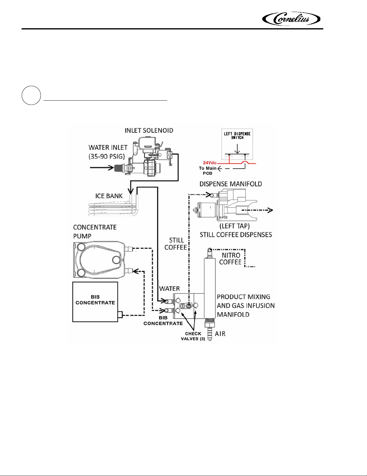
Left Tap Handle - Still Coffee Dispensing
Figure 3-3 - Still Coffee Dispense Process
Step 1) Left tap handle is pulled.
Step 2) Left Dispense switch is depressed, activating (via Main PCB):
Dispense Manifold Solenoid Valve (allows front dispensing)
Concentrate Pump (delivers coffee concentrate to Mixing Manifold)
Inlet Solenoid (delivers water to Mixing Manifold)
Action: Water and coffee concentrate combine in the mixing manifold and then flow to
the dispense manifold and into the serving cup. NOTE: There is no flow in the Nitro-coffee circuit and infusion manifold since its dispense valve is closed. The low-pressure path
is to the still-coffee dispense manifold in which the dispense solenoid valve is open.
3.0 SYSTEM OPERATION (Cont.)
3.2 Operating Processes
Publication Number: 548000106SER - 8 - © 2019, Cornelius Inc. All Rights Reserved
Page 13
3.0 SYSTEM OPERATION (Cont.)
2
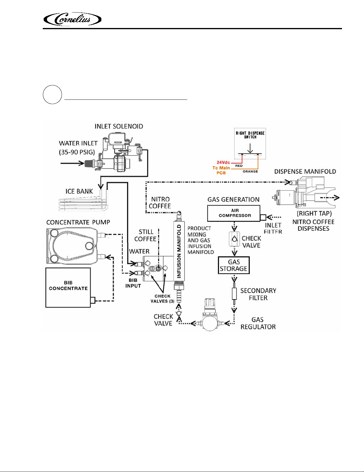
Right Tap Handle - Nitro Coffee DispensingRight Tap Handle - Nitro Coffee Dispensing
Figure 3-4 - Nitro Coffee Dispense Process
Step 1) Right tap handle is pulled.
Step 2) Right Dispense switch is depressed, activating (via Main PCB):
Dispense Manifold Solenoid Valve (allows front dispensing)
Concentrate Pump (delivers coffee concentrate to Mixing Manifold)
Inlet Solenoid (delivers water to Mixing Manifold)
Action: Water and coffee concentrate combine in the mixing manifold, are then infused
with air in the gas infusion manifold and then flow to the Nitro dispense manifold and
into the serving cup. NOTE: There is no flow in the still-coffee circuit since its dispense
valve is closed. The low-pressure path is to the Nitro-coffee dispense manifold in which
the dispense solenoid valve is open.
3.2 Operating Processes (Cont.)
Nitropro Mini Service Manual
© 2019, Cornelius Inc. All Rights Reserved - 9 - Publication Number: 548000106SER
Page 14
Nitropro Mini Service Manual
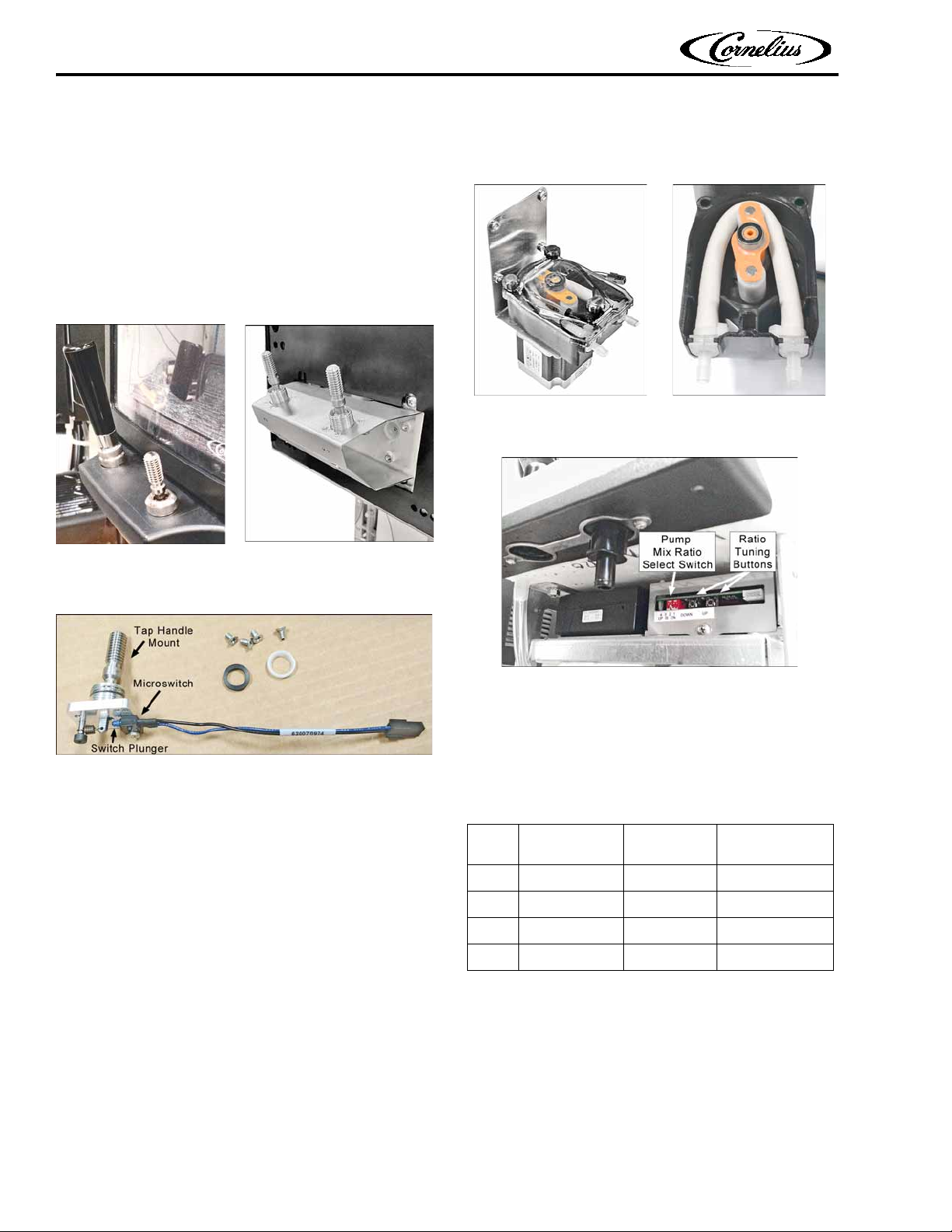
Figure 3-5 - Tap Handles / Microswitch Assemblies
Figure 3-6 - Microswitch Assembly
Figure 3-7 - Concentrate Pump
Figure 3-8 - Ratio Select Switch & Tuning Buttons
3.0 SYSTEM OPERATION (Cont.)
3.3 Component Functions
3.3.1 Tap Handles
The dispensing tap handles (Fig.3-5), when pulled,
activate microswitches (Fig. 3-6) that signal the
Main PCB to activate specific components, as described previously in section 3.2.
3.3.2 Coffee Concentrate Pump
This pump (Fig.3-7) draws coffee concentrate
from the chilled Bag In Box (BIB) and meters it to
the mixing manifold at a specific, user-selected
ratio to the input water (which is supplied at a
fixed pressure and flow rate).
Mixing ratios are adjusted by changing the DIP
switch settings on the Main PCB mounted
beneath the cabinet, as shown in Figure 3-8.
Adjustment of these settings changes the speed
of the peristaltic pump to provide more or less
concentrate per unit time.
The selectable ratios provide, from one gallon of
concentrate, the coffee yields shown in Table
3-1. (NOTE: Select one ratio - one switch ON.)
Table 3-1 - Concentrate Pump Ratios
Ratio
3:1 Switch 1 ON 1 4
4:1 Switch 2 ON 1 5
5:1 Switch 3 ON 1 6
7:1 Switch 4 ON 1 8
Main PCB
Switch Setting
Concentrate
Gallons
Coffee Yield
Gallons
Ratio Tuning Buttons: One press of a button
changes the pump motor speed by 5 RPMs (or by
0.02 - 0.08 of the average TDS value).
The peristaltic pump is driven by a 24V DC servo
motor. A maintenance kit for the pump includes a
replacement pump hose with nipple ends.
Publication Number: 548000106SER - 10 - © 2019, Cornelius Inc. All Rights Reserved
Page 15

3.0 SYSTEM OPERATION (Cont.)
Figure 3-9 - Water Inlet Solenoid
Figure 3-10 - Air Compressor and Air Storage
Figure 3-11 - Mixing-Infusion Manifold & Check Valves
Nitropro Mini Service Manual
3.3 Component Functions (Cont.)
3.3.3 Water Inlet Solenoid
This device controls the water input to the mixing
manifold. It also limits input pressure to 29 psi
(200 kPa) and limits the water flow rate within the
range of 1 to 1.25 fluid ounces (29.6 to 37 ml) per
second.
3.3.4 Air Compressor & Storage
The 24Vdc air compressor provides air to the mixing-infusion manifold to produce Nitro coffee. It
operates independently so that stored air is
always available when the Nitro-coffee tap is activated. The pressure switch stops compressor
operation when a storage-chamber pressure of 80
psi (552 kPa) is detected. The pressure-relief valve
activates at 95 psi (655 kPa) in the event of
pump-motor runaway.
3.3.5 Mixing-Infusion Manifold & Check Valves
The mixing manifold has two halves and is connected to the air-infusion manifold. Three check
valves prevent reverse flow in the supply lines and
chambers. The assembled check valves snap into
place in the manifold.
© 2019, Cornelius Inc. All Rights Reserved - 11 - Publication Number: 548000106SER
.
Page 16

Nitropro Mini Service Manual
Figure 3-12 - Dispense Manifold Assembly
Figure 3-13 - 24Vdc Power Supply
Figure 3-14 - Mixing-Dispensing Assembly
3.0 SYSTEM OPERATION (Cont.)
3.3 Component Functions (Cont.)
3.3.6 Dispense Manifold
There is a dispense manifold for each coffee type.
It receives the mixed coffee and dispenses it
through a solenoid valve that is electrically activated by the tap handle. During operation (when
open) the solenoid plunger, to which a valve seat
is attached, retracts to allow flow through the
valve orifice (Fig. 3-12).
3.3.8 Mixing-Dispensing Assembly
This removable assembly performs the mixing,
air-injection and dispensing functions of the unit.
It consists of the components identified in Figure
3-14. The air-pressure regulator allows user
adjustment of the air-infusion pressure for Nitro
coffee. The assembly is mounted in the chilled
cabinet.
3.3.7 Power Supply (24Vdc)
This unit provides DC power for the air compressor and the Main PCB.
Publication Number: 548000106SER - 12 - © 2019, Cornelius Inc. All Rights Reserved
Page 17

3.0 SYSTEM OPERATION (Cont.)
Figure 3-15 - Ice Bank and Controller Module
Figure 3-16 - Ice Bank Sensor & Agitator Motor
3.3 Component Functions (Cont.)
3.3.9 Ice Bank Chilling System
In the base of the unit resides the insulated ice
bank assembly. It is comprised of a refrigeration
unit (in the rear of the enclosure), a water/ice reservoir, an agitator/circulation pump to control ice
formation and circulate cooling water, an ice sensor and a control module, The control module
manages the refrigeration system and the agitator
based on feedback from the ice sensor. Water
from the inlet solenoid is routed through a stainless steel coil in the ice bank for chilling. As well,
cooling lines from the circulation pump are routed
into the product cabinet where a fan circulates
chilled air.
Nitropro Mini Service Manual
© 2019, Cornelius Inc. All Rights Reserved - 13 - Publication Number: 548000106SER
Page 18

Nitropro Mini Service Manual
Figure 3-17 - Front Door Switches
3.0 SYSTEM OPERATION (Cont.)
3.3 Component Functions (Cont.)
3.3.10 Front-Door Control Switches
These two switches control the merchandiser LED
backlight on the front of the door and the dispensing circuit, as indicated below.
Door Light: On/Off switch turns LED backlight on
or off.
Dispense Motor: A 3-position switch for normal
operation (ON), system shutoff (OFF) and for performing sanitizing procedures (CLEAN). In CLEAN
mode, this switch sets the concentrate pump to
the water/cleaning-agent mixing ratio (5:1). When
the switch is returned to the ON position, the mixing ratio returns to that selected on the pump
mix-ratio switch bank (Fig. 3-8).
Publication Number: 548000106SER - 14 - © 2019, Cornelius Inc. All Rights Reserved
Page 19

4.0 PREVENTATIVE MAINTENANCE
Figure 4-1 - Fans
Figure 4-2 - Ice Bank Fill & Overflow Tubes
Nitropro Mini Service Manual
4.1 Overview
Perform the procedures in this section at the
intervals indicated to ensure consistent, safe and
clean operation of the unit. These are provided in
addition to the routine cleaning and sanitizing
procedures included in the Installation & Operation manual.
4.2 Maintenance Schedule
Table 4-1 - Maintenance Schedule
Procedure Section
Refrig. condenser & cabinet fan cleaning 4.3.1 12
Ice bank level check 4.3.2 12
Concentrate pump mix ratio verification 4.3.3 12
Components visual inspection 4.3.4 12
Concentrate-pump hose replacement 4.3.5 12
Interval
(Months)
4.3 Annual Maintenance
4.3.2 Ice Bank Level Check
The water level in the ice bank may require periodic topping off to ensure optimal operation.
Check and refill it as indicated below.
The fill tube is located behind the front splash
panel and is capped with a red plug.
The small, black, overflow tube, connected to an
internal standpipe, will emit water during manual
refill when the water level reaches the full mark.
4.3.1 Refrigeration Condenser & Cabinet Fan
Cleaning
To ensure optimal cooling efficiency, clean the fan
blades and grilles of any collected dust and debris.
(The use of compressed or canned air to clean the
refrigeration condenser fan blades is adequate.)
NOTE: When the fill tube is in its stored position (as shown in Fig. 4-2) it also serves as a
‘sight glass’ indicating the bank water level.
1) Remove the drip tray and splash panel to reveal
the front of the ice bank.
2) Observe the fill tube and the water level in it. If
the water level is below the top of the tube arc,
add water to the ice bank.
3) Add filtered store water through the fill tube
after extending it from its storage position and
removing the red cap. Add water until a trickle
runs out of the black overflow tube.
4) Cap the fill tube and return it to its storage
position.
© 2019, Cornelius Inc. All Rights Reserved - 15 - Publication Number: 548000106SER
Page 20

Nitropro Mini Service Manual
Figure 4-3 - Ratio Select Switch & Tuning Buttons
4.0 PREVENTATIVE MAINTENANCE (Cont.)
4.3.3 Product Pump Mix-Ratio Verification
It is important to ensure consistency in the dispensed coffee, thus the coffee-concentrate/water
mixing ratios must be verified. Since the ratios are
selected via the Main PCB DIP switch setting, and
may sometimes require adjustment using the tuning buttons, a routine check of the ratios is essential. Follow the applicable procedure below to
verify/adjust each of the four mixing ratios.
Table 4-2 - Mix Ratio Main PCB Switch Settings
Ratio
3:1 Switch 1 ON 1 4
4:1 Switch 2 ON 1 5
5:1 Switch 3 ON 1 6
7:1 Switch 4 ON 1 8
Main PCB
Switch Setting
Concentrate
Gallons
Coffee Yield
Gallons
1) Set the DIP switch for a ratio (Fig. 4-3).
5) Stir the sample thoroughly, and measure the
TDS of the drink (refer to the TDS measuring
procedures in section 4.3.3.1).
6) If the TDS matches the desired range of the
product, no further adjustments are necessary.
If the TDS is above/below required value, use
the ‘UP’ or ‘DOWN’ Ratio Tuning buttons as
necessary to achieve the desired value. (One
press of a tuning button changes the pump
motor speed by 5 RPMs; or by 0.02 - 0.08 of
the average TDS value.
NOTE: Dispense a 16 oz. drink to purge the previous setting before measuring again.
NOTE: Make adjustments in 1-2 button pushes
to avoid overshooting the target value.
7) Once the desired value is reached, the setup is
complete and should be stable with standard
maintenance of the equipment.
8) Perform the previous steps for the remaining
three ratios to verify/adjust them.
2) Prior to installing, shake the concentrate BIB.
NOTE: If concentrate is not properly thawed, it
will adversely affect the amount of concentrate
dispensed. Thawed concentrate should be
between 35 °F (1.6 °C) to 40 °F (4.4 °C) and
have no ice particles remaining in it.
3) Dispense approximately 16 oz. of drink and discard. This is done to purge any water or coffee
dispensed using the previous settings.
4) Draw an 8 oz. drink into a clean dry cup, and
measure the temperature to confirm the drink
is between 35 to 45°F.
NOTE: The adjusted ratio settings will not be
reset by Clean mode or power loss.
NOTE: If a coffee concentrate flavor, manufacturer or ratio type is changed, repeat this process to set the ratio accurately. Conducting this
process is not necessary when changing BIBs of
the same type of coffee concentrate.
4.3.3.1 Measuring TDS (Total Dissolved Solids)
There are three methods that may be used to
check/calibrate the ratio setting of the equipment.
1. Using a TDS Meter
2. Using a Brix Meter/Refractometer
3. Manually Checking Volume Ratio
For each method, access the mix-ratio control
switches (Fig. 4-3) by removing the splash panel.
NOTE: Only one ratio select switch is allowed to
be On, with all others Off.
NOTE: Drink temperature must be maintained
to properly set the ratio of the unit.
Publication Number: 548000106SER - 16 - © 2019, Cornelius Inc. All Rights Reserved
Page 21

4.0 PREVENTATIVE MAINTENANCE (Cont.)
Nitropro Mini Service Manual
4.3.3.1 Measuring TDS (Total Dissolved Solids)
(Cont.)
OPTION 1: USING A TDS METER
A TDS meter measures the Total Dissolved Solids
in a drink. For coffee, it measures the level of
extraction and can be used to ensure that the correct mix ratio is achieved. If the TDS target is
known, a TDS meter allows for a simple process to
measure and ensure proper calibration.
1) Follow instructions for the TDS meter to ensure
proper calibration and zero setting prior to
starting this process.
2) Follow steps 1-5 in section 4.3.3 previously.
3) Using a straw, transfer a small sample of the fin-
ished drink to the TDS meter lens.
4) Check the TDS value on the meter.
5) Adjust the unit ratio setting with the tuning
buttons and purge the system by dispensing a
16 oz. drink after each adjustment.
NOTE: Since this method measures TDS, the
‘UP’ tuning button will adjust TDS up, and the
‘DOWN’ button will adjust TDS down.
OPTION 2: USING A BRIX REFRACTOMETER
A Brix refractometer is used to measure the sugar
content in aqueous solutions. This method may
not apply to all coffee concentrates, but many
concentrates have natural sugars that allow a Brix
refractometer to be used. In order to use this
method, the target Brix value must be known for
the coffee concentrate.
1) Follow instructions for the Brix refractometer
to ensure proper calibration and zero setting
prior to starting this process.
2) Follow steps 1-5 in section 4.3.3 previously.
3) Using a straw, transfer a small sample of the fin-
ished drink to the Brix refractometer meter
lens.
4) Check the Brix value on the meter.
5) Adjust the unit ratio setting with the tuning
buttons and purge the system by dispensing a
16 oz. drink after each adjustment.
NOTE: Since this method measures Brix, the
‘UP’ tuning button will adjust Brix up, and the
‘DOWN’ button will adjust Brix down.
OPTION 3: MANUALLY CHECKING VOLUME
RATIO
Additional Supplies
• Weighing scale
Following steps explain measuring the water-tocoffee-concentrate ratio using weight.
NOTE: Weight can be substituted by volume if a
weighing scale is not handy.
1) Follow steps 1-5 in section 4.3.3 previously.
2) Pull the Left & Right Tap Handles for 10 seconds
one after the other to make sure coffee is dispensing.
3) Set 10 seconds timer.
4) Pull the Left Tap Handle for 10 seconds to dispense the coffee and weigh the product dispensed.
5) Divide #4 by the total parts to get the target
coffee concentrate dispense weight.
6) a) If the total dispense is 300 grams and desired
ratio is 5:1, divide by 6 to get 50 grams concentrate target for a 10 second pour.
b) If the total dispense is 300 grams and desired
ratio is 4:1, divide by 5 to get 60 grams concentrate target for a 10 second pour.
c) If the total dispense is 300 grams and desired
ratio is 3:1, divide by 4 to get 75 grams concentrate target for a 10 second pour.
7) Turn off water to the unit.
8) Pull the Left Tap Handle for 5 seconds or until
coffee is darker and only concentrate is dispensed.
© 2019, Cornelius Inc. All Rights Reserved - 17 - Publication Number: 548000106SER
Page 22

Nitropro Mini Service Manual
Figure 4-4 - Dispense Manifold Assembly
Figure 4-5 - Concentrate Pump & Overhaul Kit
Pump Closed
Pump Open
Pump Hose
4.0 PREVENTATIVE MAINTENANCE (Cont.)
4.3.3.1 Measuring TDS (Total Dissolved Solids)
(Cont.)
OPTION 3: MANUALLY CHECKING VOLUME
RATIO (Cont.)
9) Set 10 seconds timer and dispense concentrate
by pulling the Left Tap Handle.
10) a) If weight is greater than #6 target, use the
‘DOWN’ button on controller to slow the concentrate motor down.
b) If weight is less than #6 target, use the ‘UP’
button on controller to speed up the concentrate motor.
11) Set 10 seconds timer and dispense concen-
trate by pulling the Left Tap Handle until target value from #6 is within +/- 2 grams of
target.
12) Turn water on to unit.
13) Pull the Left Tap Handle for 10 seconds until
coffee is dispensed.
14) Pull the Right Tap Handle for 10 seconds until
coffee is dispensed.
4.3.4 Components Visual Inspection
the solenoid valve plunger seal and o-ring on
the orifice insert (Fig. 4-4). Replace as the manifold assembly as required.
Cabinet Fan (Fig. 4-1): Verify operation.
Refrigeration System (Fig. 4-1): Verify ade-
quate airflow through condenser coil. Clean as
needed.
4.3.5 Concentrate-Pump Hose Replacement
Over time, the concentrate-pump internal hose
can become less pliable and the rotor and top
bearing significantly worn. To prevent a disruptive
failure, install a new pump hose annually as
described below.
1) Check the condition of each system component
for the following conditions and replace per
the instructions in section 6.0 if any are
observed.
Air/Water Hoses: Cracking, bulging, leaking.
Hose Connectors: Cracking, leaking, worn or
distorted o-rings or seals.
Ice Bank & Inlet Solenoid Spring Housing (Fig.
3-9): Water Discoloration, Contamination, Sed-
iment. (Attempt drain and flush before replacing component.)
Main PCB (Fig. 2-2): Corrosion or signs of overheated components.
Dispense Manifolds (Fig. 3-12): Check o-rings
on top portion of dispensing tubes and on the
dispensing tube, outlet-cap nipple that inserts
into the manifold. If the manifold drips, check
Publication Number: 548000106SER - 18 - © 2019, Cornelius Inc. All Rights Reserved
Page 23

4.0 PREVENTATIVE MAINTENANCE (Cont.)
Figure 4-6 - Mixing-Dispensing Assembly Removed
Pump Hose Installation
Nitropro Mini Service Manual
1) Inside the cabinet, disconnect the water and air
lines at the back of the chamber.
2) Pull each tap to relieve line pressure.
3) Shut off power to the Nitropro unit.
4) In the cabinet, unplug the wiring connector
from the mixing-dispensing assembly and
remove the assembly. Place it on the countertop (Fig. 4-6).
5) Disconnect the two hoses from the pump, note
or mark their locations for reassembly.
13) Reinstall the mixing-dispensing assembly into
the cabinet, making sure to reconnect the
plumbing and electrical connectors.
14) Confirm pump operation by dispensing both
product types until air is purged from the
lines.
6) Remove the four screws securing the pump
bracket to the assembly baseplate (access from
underneath).
7) Open the pump cover by removing the three
thumbscrews.
8) Lift out the pump rotor and bearing. Slide out
the two pump-hose nipples from the pump
housing.
9) Clean the pump-hose chamber as required.
10) Install the new pump hose. When installing it,
orient the rotor as shown in the upper photos
of Fig. 4-5 so that only one point on the hose
must be compressed.
11) Reinstall the pump cover.
12) Install the pump on the baseplate and recon-
nect the hoses.
© 2019, Cornelius Inc. All Rights Reserved - 19 - Publication Number: 548000106SER
Page 24

Nitropro Mini Service Manual
5.0 TROUBLESHOOTING
Table 5-1 - Systems-Level Troubleshooting
Malfunction Possible Causes Corrective Action
Unit will not operate
No Cooling
A. No power to unit due to tripped circuit
breaker
B. Loose or broken wiring connection to
24Vdc power supply
A. Line voltage not within nameplate specs.
causing compressor overload trip
B. No water in water ice bath or water level
very low, exposing ice bank sensing probe
C. Malfunctioning ice-bank controller or
sensing probe
D. Cabinet fan inoperative resulting in warm
concentrate (water continues to cool)
E. Compressor short cycles on overload
F. Compressor starts, hums, trips overload
G. Defective compressor overload or start
capacitor
H. Compressor starts but does not switch off
of motor-start winding
I. Refrigerant leak
A. Reset facility circuit breaker. Confirm
that breaker is correct size & no other
equipment is operating on the same
circuit. Also confirm that supply voltage is
within ±10% of name plate specification
B. Repair connection, confirm 24Vdc
output. Replace power supply as required.
A. Contact an electrician
B. Fill ice bath to proper water level (see
section 4.3.2)
C. Replace
D. Replace
E. Shut off, determine cause
F. Seized or shorted compressor, replace
G. Test & replace
H. Relay or compressor is defective. Test &
replace faulty item
I. Repair leak, evacuate & recharge system
A. Door switch is off
Merchandiser LED back-lighting panel not working
Publication Number: 548000106SER - 20 - © 2019, Cornelius Inc. All Rights Reserved
B. Harness not connected
C. No power to Main PCB control board or
board has failed
A. Turn on Door Light switch inside door
B. Remove LED panel, check harness
connections
C. Measure power input to Main PCB.
Replace fuse or board if necessary (see Fig.
6-1)
Page 25

Nitropro Mini Service Manual
5.0 TROUBLESHOOTING (Cont.)
Table 5-2 - Drink-Quality Troubleshooting
Malfunction Possible Causes Corrective Action
Dispensed coffee is too weak
Dispensed coffee is too strong
Excessive foam in Nitro
coffee
A. Incorrect ratio DIP switch selected for
product ratio being used
B. Brix adjustment needs to be made
C. Concentrate hose or pump-motor malfunction
A. Incorrect ratio DIP switch selected for
product ratio being used
B. Brix adjustment needs to be made
C. Water pressure too low
A. Air regulator in cabinet not set properly
B. Regulator not holding set point. Pressure
reading is drifting upwards
C. Air-storage pressure-switch malfunction
(causing high pressure)
A. Confirm product ratio and select
appropriate ratio DIP switch
B. Using the ratio-tuning buttons located
behind the splash panel, press the UP
button to increase pump speed and
recheck Brix measurement
C. Verify BIB connection and harness connection to concentrate pump
A. Confirm product ratio and select
appropriate DIP switch
B. Using the ratio-tuning buttons located
behind the splash panel, press the DOWN
button to decrease pump speed and
recheck Brix measurement
C. Verify water supply to unit is in range
A. Pull regulator knob outward turn CW for
more air or CCW for less air injection
B. Bleed off all pressure and reset
regulator. If after setting pressure the
gauge reading continues to drift upward,
replace the regulator
C. Inside cabinet, connect pressure gauge
to air outlet quick disconnect (see Sec.
5.1). Gauge should read 75 to 85 psi (517
to 586 kPa). If reading is outside of range,
replace pressure switch
Warm drinks
Concentrate is warm, water is
cold
A. Environment around dispenser too warm
B. Excessive demand on dispenser
C. Dirty condenser coil
D. Inoperative condenser fan
E. Defective ice bank control module
F. Refrigerant low due to leak in system
G. Defective ice probe
A. Cabinet fan malfunction
B. Product box too close to fan
C. Agitator motor/pump malfunction or
output is restricted
D. Loss of refrigerant charge due to leak in
system
A. Relocate dispenser
B. Add a water precooler or a second
dispenser to divide usage load
C. Clean condenser coil
D. Replace condenser fan motor
E. Test & replace if necessary
F. Repair leak and recharge system
G. Check and replace as necessary
A. Check/replace fan
B. Move product box away from fan
C. Check/replace agitator motor, check
water lines & flow
D. Repair leak, recharge system
© 2019, Cornelius Inc. All Rights Reserved - 21 - Publication Number: 548000106SER
Page 26

Nitropro Mini Service Manual
5.0 TROUBLESHOOTING (Cont.)
Table 5-3 - Compressed Air & Infusion Troubleshooting
Malfunction Possible Causes Corrective Action
No gas infusion on right side
tap (no foam in Nitro coffee)
Air compressor not turning
on
Air compressor cycling on/off
too frequently
Air compressor runs
continuously
A. Infusion air regulator in cabinet is not set
properly
B. The air compressor did not activate or is
cycling on/off
C. Sparger (infusion manifold) clogged, dirty
D. Stuck check valve
A. Malfunctioning pressure switch
B. Malfunctioning 24 Vdc power supply
C. No voltage to air compressor
D. Malfunctioning air compressor
A. Leak in the compressed air circuit
B. Air-storage relief valve not fully seating
C. Pressure switch malfunction
A. Leak in the compressed air circuit
B. Malfunctioning pressure switch
C. Air-storage relief valve not fully seating
due to obstruction
D. Air-storage relief valve worn out
A. Pull regulator knob outward, turn CW
for more air injection or CCW for less
B. See air compressor symptoms
C. Preform the weekly sanitize/cleaning
procedure (per Install-Operator manual)
D. Flush out, same as C above.
A. Check pressure switch for continuity
with zero pressure in system. If circuit is
open, replace switch
B. Confirm output voltage is 24VDC at
power supply. Replace as required
C. Measure for 24VDC at compressor,
inspect wire connections, power supply
D. If air compressor is receiving 24 Vdc,
replace it
A. Leak check circuit starting at compressor
through to air regulator in cabinet. Repair
or replace defective component
B. Pull relief valve ring and purge any
possible debris. If it continues to leak,
replace relief valve
C. Check pressure switch per Sec. 5.1.
A. Leak check circuit starting at compressor
through to air regulator in cabinet. Repair
or replace defective component
B. Check pressure switch for continuity
with zero pressure in system. If circuit is
open, replace switch
C. Pull relief valve ring and purge any
possible debris. If it continues to leak,
replace relief valve
D. Hold down relief valve stem and allow
air compressor to cycle & shut off at 80 psi.
Release stem and if it still leaks, replace
the relief valve
Publication Number: 548000106SER - 22 - © 2019, Cornelius Inc. All Rights Reserved
Page 27

Nitropro Mini Service Manual
5.0 TROUBLESHOOTING (Cont.)
Table 5-4 - Dispensing-Function Troubleshooting
Malfunction Possible Causes Corrective Action
Nothing dispenses when tap
handle is pulled (refrigeration
is operating)
No water dispensed, concentrate only
A. Door inner Dispense Motor switch is off
B. Mixing-Dispensing assembly wiring
harness is disconnected
C. Door interlock switch is open
D. Tap microswitch is not activating
E. Dispense solenoid valve or water inlet
solenoid not opening
F. Clogged orifice at dispense manifold valve
or in dispense-tube cap
G. No output from 24 Vdc power supply
H. No power to Main PCB or board has
failed
A. Water line inside cabinet is disconnected
from mixing-dispensing assembly
B. No water to dispenser, supply is off
C. Water inlet solenoid (at the rear of unit)
is clogged, binding or defective
D. Freeze-up of water coil in ice bank
A. Turn on Dispense Motor switch
B. Connect harness in cabinet-wall socket
C. Door must be closed to allow
dispensing. Check interlock switch
operation & replace if necessary
D. Remove tap handle and inspect lever for
damage, verify switch operation, replace as
required (see section 6.10)
E. Verify 24 Vdc at both solenoids when
dispense switches are activated
F. Preform the weekly sanitize/cleaning
procedure in Install-Operator manual
G. Confirm power supply output voltage is
a steady 24 Vdc
H. Measure 24 Vdc input to board. Replace
fuse or board if necessary (see Fig. 6-1)
A. Reconnect water quick-disconnect
B. Restore water supply
C. Confirm 24 Vdc is present at solenoid
during dispensing; confirm solenoid coil is
not open-circuited; replace as required
D. Unplug dispenser & allow ice bank to
thaw for 2-4 hrs. Verify operation of
agitator motor & ice bank control; replace
components as required
No concentrate dispensed,
water only
Unit continues to dispense
after tap handle is released or
dispenses without operator
action
Product continuously drips
from dispense tube in OFF
mode
Pulsing effect in coffee stream
while dispensing
A. BIB hose end not fully engaged into
connector on mixing-dispensing assembly
platform in cabinet
B. Concentrate too cold, not properly
thawed
C. Malfunctioning pump motor
D. No power to Main PCB or board failed
A. Dispense lever or dispense microswitch is
stuck in ON position
A. Water inlet solenoid at rear of unit or
dispense manifold solenoid valve is not
shutting off completely
A. Facility water pressure low, below 30 psi
B. Water inlet solenoid binding or pressure-
control components are malfunctioning
C. Concentrate pump malfunctioning
A. Check connector o-rings, fully insert BIB
hose end into connector
B. Concentrate should be 35 to 40 °F (1.7 to
4.5 °C) with no ice prior to loading
C. Verify BIB hose connection and wiring
harness connection to pump
D. Measure 24 Vdc power input to board.
Replace fuse or board if necessary (see Fig.
6-1)
A. Remove tap lever shroud (sec. 6.10) and
inspect dispense switch and wiring harness
A. Flush/clean solenoid(s), replace parts as
necessary (see sections 6.4.3 & 6.6)
A. Correct water supply pressure to ensure
constant 35-90 psi (2.5-6.2 bar) is being
provided to unit
B. Clean and/or replace as necessary
C. Verify operation, replace as necessary
© 2019, Cornelius Inc. All Rights Reserved - 23 - Publication Number: 548000106SER
Page 28

Nitropro Mini Service Manual
Figure 5-1 - Air Inlet Line
5.0 TROUBLESHOOTING (Cont.)
5.1 Air-Compressor Pressure Verification
This procedure is a measurement of the air pressure in the air storage chamber to determine if
the air pump is working properly and shutting off
when the pressure is approximately 80 psi (552
kPa).
1) Shut off power to the Nitropro unit.
2) Inside the cabinet, disconnect the dispenseassembly air line from the back wall air inlet.
Connect a 100 psi (689 kPa) air pressure gauge
with a quick-connect fitting to the Air Inlet line
(Figure 5-1).
3) Apply power to the unit.
4) Dispense a Nitro coffee drink or two to trigger
air-compressor operation.
5) Observe the pressure gauge.
6) The compressor should stop running at a reading of 75 to 85 psi (517 to 586 kPa). If the pressure is out of range, check for leaks and check/
replace the storage-chamber pressure switch.
Publication Number: 548000106SER - 24 - © 2019, Cornelius Inc. All Rights Reserved
Page 29

6.0 COMPONENT REPLACEMENT
!
WARNING!
!
CAUTION!
Nitropro Mini Service Manual
This section provides instructions or guidelines on
replacing the various Nitropro Mini components.
6.1 Safety Precautions
Disconnect power to the unit before servicing or replacing electrical components. Follow all lock out/tag out procedures
established by the user. Verify all power is
disconnected from the unit before performing any work. Failure to comply could result
in serious injury, death or damage to the
equipment.
When replacing or testing electronic components, be sure to wear a static strap connected to chassis ground. This protects the
electronic components from any static discharge while working on the unit. (This specifically applies to handling of a new Main
PCB or an Ice-Bank Controller module.)
NOTE: Use the hinge cover to collect the panel
screws removed.
6.2 Access Panel Removal
Follow the steps in the photos below to remove
the access panels in the required order.
© 2019, Cornelius Inc. All Rights Reserved - 25 - Publication Number: 548000106SER
Page 30

Nitropro Mini Service Manual
6.0 COMPONENT REPLACEMENT (Cont.)
6.2 Access Panel Removal (Cont.)
Publication Number: 548000106SER - 26 - © 2019, Cornelius Inc. All Rights Reserved
Page 31

6.0 COMPONENT REPLACEMENT (Cont.)
Figure 6-1 - Main PCB Housing Removed
6.3 Main PCB
1) Shut off power to the Nitropro Mini and unplug
its power cord from the wall receptacle.
2) Remove the drip tray and splash plate.
3) Remove the Phillips screw securing the metal
housing of the Main PCB (Fig. 6-1).
4) Withdraw the Main PCB from the unit and
unplug its three wiring connectors.
5) Replace and secure new PC board/mounting
plate assembly in the unit with the supplied
screw.
6. Setup the mix-ratio select switches by following
the procedure in the install manual or section
4.3.3 of this manual.
Nitropro Mini Service Manual
7. Apply power to the unit and confirm that the
green, heartbeat LED on the PCB is blinking,
indicating that the board is functioning properly.
© 2019, Cornelius Inc. All Rights Reserved - 27 - Publication Number: 548000106SER
Page 32

Nitropro Mini Service Manual
Figure 6-2 - Mixing-Dispensing Assembly in Cabinet
Figure 6-3 - Mixing-Dispensing Assembly in Cabinet
6.0 COMPONENT REPLACEMENT (Cont.)
6.4 Mixing-Dispensing Assembly
Components
This assembly contains multiple components that
typically must be unfastened from the baseplate
(underside mounting screws) or from the upper
brackets employing through-hole mounting.
Assembly Removal from Cabinet
1) In the cabinet, disconnect the air/water supply
lines and the wiring connector.
2) Pull the assembly release latch (Fig. 6-2) forward and then lift the assembly out of the cabinet and place it on a bench or countertop.
3) Replace components by following the appropriate instructions below.
6.4.1 Air Pressure Regulator
1) Unscrew the black, threaded ring under the
regulator adjustment knob and the bracket.
Withdraw the regulator from its mounting
bracket to access the air hoses.
2) Unfasten the air hoses. noting or marking their
locations. Remove the regulator.
3) On the old regulator, turn its adjustment knob
clockwise and count the turns until it stops.
4) On the new regulator, turn its adjustment knob
clockwise until it stops (closed). Then open it
the number of turns counted in step 3.
Publication Number: 548000106SER - 28 - © 2019, Cornelius Inc. All Rights Reserved
Page 33

6.0 COMPONENT REPLACEMENT (Cont.)
Figure 6-4 - Mixing Manifold Hose Fittings Removal
!
CAUTION!
Figure 6-5 - Hose Clamp Removal (Oetiker Tool)
Figure 6-6 - Dispense Manifold Assembly
6.4.1 Air Pressure Regulator (Cont.)
5) Connect the new regulator to the air hoses.
6) Reinstall the regulator in reverse order.
7) Confirm operation and adjust as required.
6.4.2 Mixing - Infusion Manifold
1) On the underside of the assembly baseplate,
remove the screws securing the mixing-infusion manifolds (Fig. 6-3).
2) Use tape and a marker to label the five hoses.
3) Loosen the C-plate retainer screws where the
four hoses connect to the manifold (Fig. 6-4).
6) Remove the hose and unscrew the threaded,
hose-nipple fitting. Clean off the Teflon tape
and apply new tape (or use an NSF 61 pipesealing dope, such as T Plus 2 by Rector Seal).
7) Remove the mixing-infusion manifold and place
the new one in the mixing-dispensing assembly.
Nitropro Mini Service Manual
4) Move a retainer plate aside and rotate the hose
fitting back and forth while withdrawing it
from the manifold. Remove the four fittings.
Check/replace their o-rings as needed.
5) Carefully remove the threaded, hose-nipple fitting from the infuser manifold by first removing the hose clamp using side cutters or the
recommended Oetiker HIP 2800 Es crimping/
cutting tool (see Fig. 6-5). Cut the clamp open.
8) Reinstall the hoses in reverse order. When
tightening the threaded, hose-nipple fitting in
the infuser manifold, tighten it finger tight and
then rotate it 2 to 3 turns to prevent leakage.
Use the Oetiker crimping tool to install the
hose clamp on the hose-nipple fitting.
9) Secure the manifold assembly to the baseplate
by reinstalling the underside screws.
10) Reinstall the mixing-dispensing assembly in
the cabinet, operate the dispenser and check
all the manifold hose connections for leaks.
6.4.3 Dispense Manifold
1) Remove the assembly-underside screws that
secure the manifold (Fig. 6-6) to the baseplate.
Be careful to avoid damaging the tubing
when removing the hose clamp.
© 2019, Cornelius Inc. All Rights Reserved - 29 - Publication Number: 548000106SER
2) Unplug the two solenoid wires and disconnect
the hose from its port.
Page 34

Nitropro Mini Service Manual
Figure 6-7 - Air Compressor and Storage Chamber
6.0 COMPONENT REPLACEMENT (Cont.)
6.4.3 Dispense Manifold (Cont.)
3) Remove the dispense manifold and replace it
by following the previous steps in reverse
order.
6.4.4 Concentrate-Pump
Refer to section 4.3.5 Concentrate-Pump Hose
Replacement for pump removal instructions.
6.5 Air Compressor Removal
The air compressor (Fig. 6-7) is located in the left
rear of the enclosure and is mounted on a carrier
plate to allow removal.
1) Shut off the power to the dispenser and unplug
the power cord from the wall receptacle.
2) Remove the top, back, and left access panels
from the dispenser.
3) With power off, pull the relief valve ring to
depressurize the air storage chamber.
4) Install the new air filter by firmly pressing the
air hose into each filter-connector end.
4) Disconnect the air line from the storage chamber top cover.
5) Remove the 4 screws indicated in Figure 6-7.
6) Remove the compressor partially from the
enclosure and disconnect the black ground
wire from the motor and the red wire from the
4 amp breaker terminal.
7) At this point you may service the compressor
by replacing the pressure switch, relief valve,
check valve, motor/compressor assembly or
the storage chamber gasket. Otherwise, transfer the plumbing components necessary to the
new compressor and install them in reverse
order.
6.5.1 Compressor Air Filter Replacement
1) Perform steps 1 -3 shown above in section 6.5.
2) Note the orientation of the air filter (Fig. 6-7).
3) Disconnect the air filter from the air line by
pressing on the dark gray ring on the hose side
of each connector while withdrawing the hose.
Publication Number: 548000106SER - 30 - © 2019, Cornelius Inc. All Rights Reserved
Page 35

6.0 COMPONENT REPLACEMENT (Cont.)
Figure 6-8 - Water Inlet Solenoid & Mounting
Figure 6-9 - 24Vdc Power Supply & Mounting
Nitropro Mini Service Manual
6.6 Water Inlet Solenoid
7) Connect the dispenser water hose to the
replacement solenoid.
8) Reinstall the solenoid in reverse order.
6.7 Power Supply (24Vdc)
1) Shut off power to the dispenser and unplug the
power cord from the wall receptacle.
2) Remove the enclosure top panel and then the
right-side access panel from the dispenser.
3) Disconnect the AC wiring from the top of the
power supply (Fig. 6-9).
1) Shut off the water supply to the unit and then
dispense a still coffee (left tap handle) drink to
relief any water pressure in the lines.
2) Shut off power to the dispenser and unplug the
power cord from the wall receptacle.
3) Remove the enclosure top panel and then the
right-side and rear access panels from the dispenser.
4) Disconnect the water-supply hose from the
inlet solenoid.
5) Remove the two back-panel, Phillips screws
securing the inlet solenoid bracket.
6) Partially remove the inlet solenoid and then
remove the dispenser water-inlet hose from it.
© 2019, Cornelius Inc. All Rights Reserved - 31 - Publication Number: 548000106SER
4) Remove the screws securing the power supply
to the enclosure rail.
5) Remove the power supply partially from the
enclosure and disconnect the DC wiring from
the bottom terminals. Then remove it entirely.
6) Install the new power supply in reverse order.
Page 36

Nitropro Mini Service Manual
Figure 6-10 - Merchandiser LED Backlight Removal
Figure 6-11 - Ice Sensor Probe
6.0 COMPONENT REPLACEMENT (Cont.)
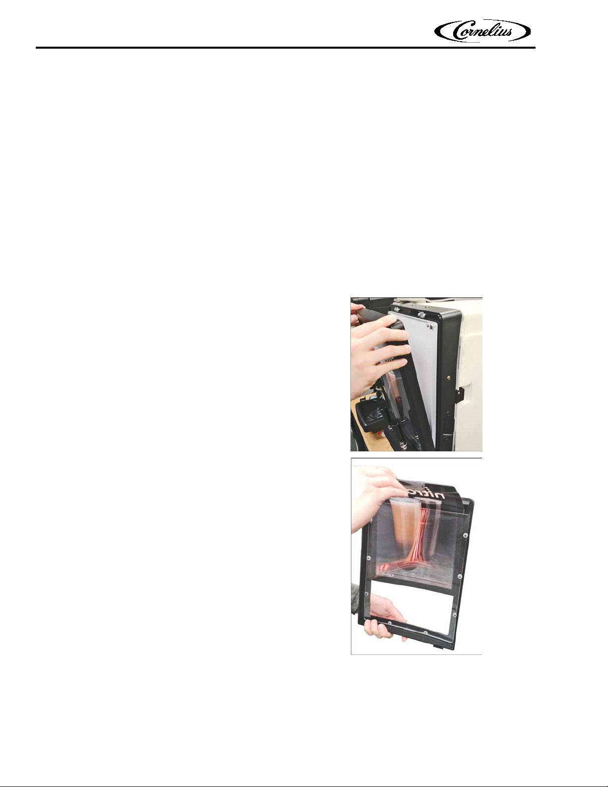
6.8 Merchandiser LED Back-Lighting Panel
This panel is mounted to the cabinet door behind
the merchandiser window. Its control module can
be accessed by removing the light panel.
1) Shut off power to the dispenser and unplug the
power cord from the wall receptacle.
2) Remove the merchandiser window by pulling
firmly on the frame molding surrounding it, at
the top, as shown in Figure 6-10.
6.9 Ice Bank
The Ice Bank consists of multiple components that
are replaceable. They include:
1) Ice Sensor Probe
2) Agitator/Pump Motor & Bath Impeller
3) Electronic Control Module
4) Refrigeration Components
6.9.1 Ice Sensor Probe
3) Remove the corner screws securing the light
panel to the cabinet door.
4) Disconnect the wiring at the back of the panel.
5) Connect the new panel wiring and reinstall the
light panel in reverse order.
Publication Number: 548000106SER - 32 - © 2019, Cornelius Inc. All Rights Reserved
1) Shut off power to the dispenser and unplug the
power cord from the wall receptacle.
2) Remove the enclosure top panel and then the
left-side and rear access panels from the enclosure.
NOTE: The ice sensor is located at the left-rear
of the enclosure (Fig. 6-12) and sensor removal
may be performed from the enclosure rear.
Page 37

6.0 COMPONENT REPLACEMENT (Cont.)
Figure 6-12 - Ice Sensor & Control Module Locations
Figure 6-13 - Agitator Motor Location & Underside
Nitropro Mini Service Manual
6.9.1 Ice Sensor Probe (Cont.)
It is recommended, for easier sensor-cable
routing and plugging/unplugging from the control module, to remove the air compressor unit
for improved access.
3) Unplug the sensor cable from the ice-bank controller module.
4) Remove the two black thumbscrews securing
the ice sensor probe and then lift the sensor
out of the ice bank. Note its orientation.
6.9.2 Agitator Motor
The agitator motor is located centrally on the ice
bank cover plate (Fig. 6-13). Obtain the most convenient access by removing the air compressor.
Remove the thumbscrew shown to unfasten the
agitator motor from its mounting.
5) Install the new sensor in the ice bank. Route its
cable to the controller module and plug it in.
© 2019, Cornelius Inc. All Rights Reserved - 33 - Publication Number: 548000106SER
Page 38

Nitropro Mini Service Manual
Figure 6-14 - Agitator Wiring Socket on Controller Module
Figure 6-15 - Agitator Pump Hose Orientations
Figure 6-16 - Ice Bank Controller Module Removal
6.0 COMPONENT REPLACEMENT (Cont.)
6.9.2 Agitator Motor (Cont.)
1) Shut off power to the dispenser and unplug the
power cord from the wall receptacle.
2) Remove the enclosure top panel and then the
left-side and rear access panels.
3) Remove the air compressor from the left side of
the enclosure (refer to section 6.5).
4) Unplug the agitator-motor wiring plug from the
ice bank controller module socket (Fig. 6-14).
NOTE: You can obtain access to the controller
wiring sockets by removing the splash shield
and the Main PCB housing refer to section 6.3).
6.9.3 Ice Bank Controller
1) Shut off power to the dispenser and unplug the
power cord from the wall receptacle.
5) Loosen the thumbscrew at the base of the agitator motor (Fig. 6-13).
2) Remove the enclosure top panel and then the
left-side access panel.
3) Remove the drip tray, splash panel and the
Main PCB housing (refer to section 6.3).
4) Unplug the four wiring connectors from the ice
bank controller module (Fig. 6-16).
6) Lift and angle the motor assembly to withdraw
it from the ice bank.
7) Install the replacement motor in reverse order.
Publication Number: 548000106SER - 34 - © 2019, Cornelius Inc. All Rights Reserved
Page 39

6.0 COMPONENT REPLACEMENT (Cont.)
!
WARNING!
Figure 6-17 - Tap Handle/Microswitch Mounting
Nitropro Mini Service Manual
6.9.3 Ice Bank Controller (Cont.)
5) Slide the controller to the right, off its mounting and remove the controller.
6) Install the replacement controller in the reverse
manner.
6.9.4 Refrigeration Components
Only trained and certified refrigeration
technicians should service the Nitropro
Mini refrigeration system components.
FAILURE TO COMPLY COULD RESULT IN
SERIOUS INJURY, DEATH OR EQUIPMENT
DAMAGE.
ALL REFRIGERATION SERVICE PROCEDURES MUST CONFORM TO LOCAL CODES,
ENVIRONMENTAL AND PROFESSIONALPRACTICE STANDARDS.
6.10 Tap Microswitches
Each tap handle activates a microswitch connected to the Main PCB. The microswitches are
mounted on the base plates of the tap handle
assemblies. Access is achieved by removing the
tap-handles and the mounting rings that secure
each mechanical activator assembly.
1) Shut off power to the dispenser and unplug the
power cord from wall receptacle.
2) Carefully unscrew each tap handle from its activator-pin assembly (Fig. 6-17).
3) Unscrew and remove each retainer ring as
shown.
Ensure that the refrigerant charge is captured by appropriate equipment before the
system is opened for the servicing of pressurized components.
NOTE: It may be helpful to the refrigeration technician to review the dispenser-particular guidance
in the following Troubleshooting tables and specific Malfunctions of section 5.0 Troubleshooting.
Table 5-1: No cooling
Table 5-2: Warm drinks; Concentrate is
warm, water is cold
Additionally, refrigeration information in section
2.1 Nitropro Functions & Specifications should be
helpful:
Table 2-2 - Refrigerant Type
4) Carefully lift the surrounding plastic housing off
of the tap-handle mounts to expose the
microswitch assemblies.
© 2019, Cornelius Inc. All Rights Reserved - 35 - Publication Number: 548000106SER
Page 40

Nitropro Mini Service Manual
Figure 6-18 - Tap Handle Microswitch Assembly
6.0 COMPONENT REPLACEMENT (Cont.)
6.10 Tap Microswitches (Cont.)
5) Remove the 4 screws securing each tap-handle
switch assembly to the metal bracket and disconnect the wiring leads (Fig. 6-18).
6) Remove the switch assembly and install the
new one. Mount the assembly on the support
bracket and reconnect the wiring leads.
7) Reinstall the plastic cover over the tap-handle
switch mountings and secure with the
threaded retainer rings. Reinstall the tap handles.
8) Verify operation of the taps.
Publication Number: 548000106SER - 36 - © 2019, Cornelius Inc. All Rights Reserved
Page 41

APPENDIX A - SYSTEM DRAWINGS
Figure A-1 - Plumbing Diagram
Nitropro Mini Service Manual
© 2019, Cornelius Inc. All Rights Reserved - 37 - Publication Number: 548000106SER
Page 42

Nitropro Mini Service Manual
Figure A-2 - Electrical Diagram
APPENDIX A - SYSTEM DRAWINGS (Cont.)
Publication Number: 548000106SER - 38 - © 2019, Cornelius Inc. All Rights Reserved
Page 43

Nitropro Mini Service Manual
© 2019, Cornelius Inc. All Rights Reserved - 39 - Publication Number: 548000106SER
Page 44

Nitropro Mini Service Manual
Publication Number: 548000106SER - 40 - © 2019, Cornelius Inc. All Rights Reserved
Page 45

Cornelius Inc.
www.cornelius-usa.com
 Loading...