

Cornelius MILLENNIUM MJ41-6PB, MILLENNIUM MJ40-6PC, MILLENNIUM MJ41-6PC, MILLENNIUM MJ40-6PB, MILLENNIUM MJ42-6PB Installation & Service Manual
...
MILLENNIUM
INSTALLATION & SERVICE MANUAL
Model MJ40-6PB
MJ41-6PB
MJ42-6PB
MJ40-6PC
MJ41-6PC
MJ42-6PC
One Cornelius Place, Anoka, Minnesota 55303
Phone (800) 238-3600 or (612) 421-6120 Fax (612) 422-3255
CORNELIUS INC.
Part No. 85305
Rev:E
Revision Date: May 09, 2014

Table of Contents
Description ...............................................................................................................................Page 2
Specifications ...........................................................................................................................Page 3
Receiving & Unpacking...........................................................................................................Page 4
Installation................................................................................................................................Page 4-5
• Connect Drain
• Connect Water Supply
• Fill Ice Water Bath
• Connect Power Supply/Start Refrigeration
• Purge Air from System
• Connect B-I-B Concentrate
• Priming the Concentrate Pumps
• Sanitizing prior to Initial Use
• Apply Sealant to Base & Counter Top
Programming Instructions........................................................................................................Page 6
Notes.........................................................................................................................................Page 7
Brixing Concentrate .................................................................................................................Page 8
Cleaning & Sanitizing the System............................................................................................Page 8
• Flushing the Concentrate Lines & Valves
• Cleaning & Sanitizing the Concentrate Lines & Valves
Daily Cleaning & Maintenance................................................................................................Page 9
Maintenance of the Refrigeration System................................................................................Page 9-10
• Cleaning of the refrigeration Components
• Ice Water Bath Cleaning
Troubleshooting Guide.............................................................................................................Page 11-17
Wiring Diagram........................................................................................................................Page 18
Exploded View/Parts Identification .........................................................................................Page 19-29
Wiring Diagram Portion Control..............................................................................................Page 30
Recommended Spare Parts (Service Agents Only)..................................................................Page 31
Optional Accessories................................................................................................................Page 32
1
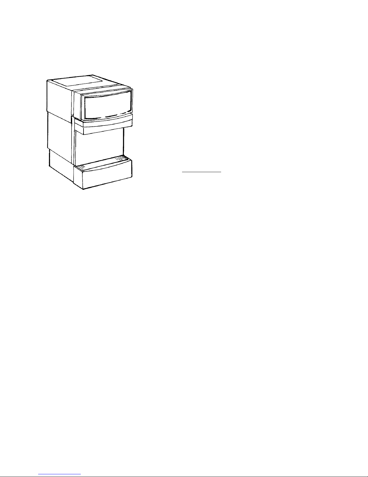
General Description
The Millennium™ is a state of the art six product B-I-B juice
dispenser. It’s integral high performance, dual speed peristaltic mini
pumps eliminate the need to purchase separate B-I-B pumps. The
Millennium™ can draw product directly from the B-I-B’s up to 50
feet away (15 feet vertically) allowing for greater installation
flexibility! Additionally, the Millennium™ incorporates a unique
valve assembly which mixes the concentrates more thoroughly than
similar models.
Wilshire realizes that counter space is at a premium in any
operation. The Millennium™ maximizes the use of counter space by
providing six product capability in a 19 inch wide chassis. Because
the air circulation is through the top, the Millennium™ can be
installed with zero clearance in the back and sides. For improved
serviceability, all components can be accessed through the top or
front without disturbing equipment placed on either side.
With it’s innovative compact design, reduced operating expense, ease of use and service we’re certain the
Millennium will meet the most demanding conditions for many years to come.
2

Specifications
Model Number ........................................................MJ40-6 – 115 VAC/1 Phase 60Hz, 8.0 Amps
Electrical Ratings ....................................................MJ42-6 – 230 VAC/1 Phase/50 Hz, 4.0 Amps
.................................................................................MJ41-6 – 200 VAC/1 Phase/60 Hz, 4.0 Amps
Electrical Connection ..............................................3 Prong Plug w/Ground Supplied 120v/60
.................................................................................2 Amp Prong w/Ground Supplied with Export Models
Power Supply ..........................................................15 Amps at 120 volts or 10 Amps at 220 volts
Water Requirements................................................3/8 in. (9.5 mm.) SAE male flare inlet
.................................................................................20-100psi (1.4-7bar) max. static pressure
.................................................................................3.0 oz. (88.7 ml.) water flow per second
Refrigeration............................................................10.5 oz. R-134a Refrigerant
.................................................................................1/3 hp. Compressor
.................................................................................Test Pressures:
................................................................................. High 460 psi (31.2 bar)
................................................................................. Low 200 psi (13.5 bar)
.................................................................................Air Cooled Condenser
Recommended Clearance........................................4 in. (10.16 cm.) on top
Weight.....................................................................Shipping, 160 lbs. (72.6 kg.)
.................................................................................Operation, 266 lbs. (120.7 kg.)
Approvals ................................................................U.L., C.U.L., N.S.F.
* Low speed rating is 2/3 of the high speed
3
Receiving & Unpacking
1. Inspect the carton and note any damage,
regardless if it appears minor. If the carton is
damaged, note on the consignee copy of the
freight invoice “exterior carton damage concealed damage possible.”
2. Cut the plastic banding strap and remove the
exterior carton sleeve, internal fillers and
plastic bag around the dispenser. Carefully
inspect for damage.
Note: Wilshire is not responsible for damaged
freight. If damage is found, you must save all
packaging material and contact the freight
carrier. Failure to contact the carrier within 48
hours of receipt may void your claim.
can support a minimum of 300 lbs.
directly below the dispenser.
Installation
Typically the dispenser is placed directly on the
counter and a food grade silicone sealant applied
around the base. However, an optional leg kit
(# 48499) is available. The following
instructions assume the optional leg kit will not
be used.
Depending on the type of counter, it may be
necessary to provide access through the counter
at the rear of the dispenser for the drain, power,
water and concentrate connections.
Refer to the template enclosed in the
installation kit.
3. Confirm receipt of the installation kit
#48458 packaged with the dispenser. If any
item is missing, contact our customer
service department at 1-800-344-3801
Monday-Friday between the hours of 8:00
AM & 4:30 PM CST.
Kit Contents:
Qty Description
1 3/8” Barb
2 3/8” swivel nut
7 3/8”x3/8” elbow barb
8 3/8” nylon washer
2 #170 clamps
12 #140 clamps
4 ft. 3/8” braided tubing
6 ft. 1/2” I.D. clear tubing
1 1/2”x1/2” 90o elbow
6 Generic B-I-B connectors
2 Flavor strip kits
1 Installation template
4. Remove the four 9/16” (15 mm) retaining
bolts from the underside of the shipping
pallet by carefully tilting the dispenser from
side to side.
5. With the assistance of another person, lift
the dispenser from under the base and place
it on the counter.
The dispenser is extremely heavy when
operational. Make certain the counter
Connect Water Supply:
Water pipe connections and fixtures directly
connected to a potable water supply shall be
sized, installed, and maintained according to
federal, state, and local laws.
Wilshire recommends that a ½” O.D. copper
supply line with a shut-off valve and water filter
be located within 3-6 feet (0.91-1.83 m) of the
dispenser.
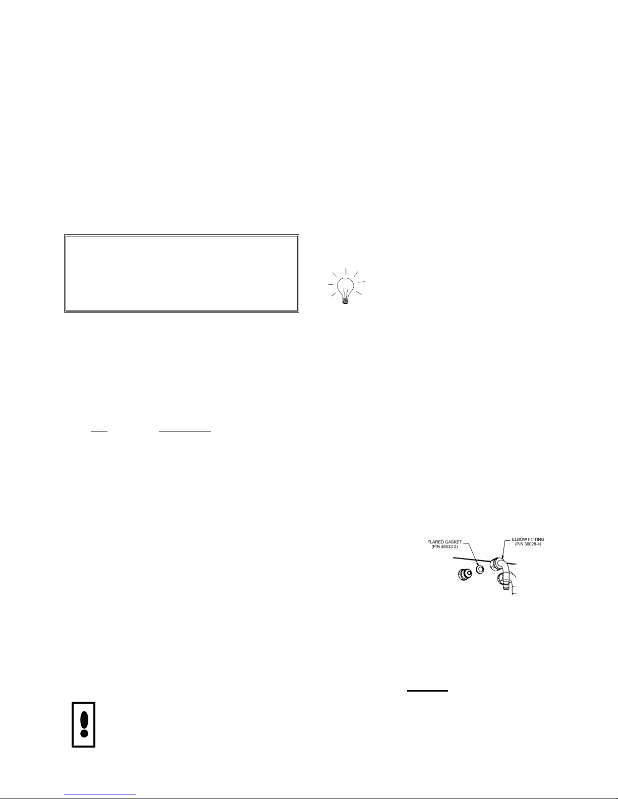
a. Assemble the 3/8” braided water supply line
furnished in the Installation Kit by attaching the
straight barb on one end and the elbow barb on
the other. Secure with clamps provided.
b. Insert a 3/8” nylon washer into the elbow
barb of the supply
line. Connect the
assembled supply
line to the water
inlet fitting located
on the rear of the
dispenser
c. Connect the water supply line to the shut
off. Turn on the water and check for leaks.
NOTE: The dynamic water pressure must be 20
PSIG (1.4 bar) minimum to ensure correct valve
flow control and must not exceed 100 PSIG (7
bar) to avoid valve damage.
4

Fill Ice Water Bath:
Purge Air from the Water Coil:
a. Remove the top cover
b. Remove the large red plastic plug from the
filler hole in the top of the refrigeration deck.
c. Fill the water bath with cool water until it
begins to trickle out of the overflow tube.
d. Reinstall the red plastic plug and top cover.
Connect power Supply / Start
Refrigeration:
a. Start the refrigeration system by plugging
the power cord into a 115 VAC (+ 10%), 15 amp
grounded receptacle.
The Millennium forms an ice bank of
approximately 40 lbs. (18.15 kg) in 5-6 hours at
a room temperature of 75oF (24 oC). Once the ice
bank has grown to the proper size, the ice bank
control will shut down the refrigeration circuit.
NOTE: It is normal to see water trickle from
the over flow as the ice bank forms.
Connect B-I-B Concentrate:
a. Attach the supplied 3/8” (9.5mm) elbow
barbs to the end of each 3/8” I.D. B-I-B
concentrate supply line (not supplied). Secure
with clamps provided. Insert a 3/8” nylon washer
into the elbow barb and connect the supply lines
to the rear of the dispenser noting the valve
numbering (numbered 1-6 from left to right as
viewed from the front of the dispenser).
b. Route the concentrate supply lines to the B-I-
B location and attach the gray plastic B-I-B
connector (supplied) to the end of each line.
Secure with clamps provided.
Prior to initial use, purge all air from the valves
by pushing the dispensing switch repeatedly.
Continue until a steady flow of water is
observed. Repeat the above on the remaining
valves.
Priming the Concentrate Pumps:
a. Turn off the water supply.
b. Connect the concentrate lines to their
respective B-I-B.
c. Depress and hold each start button until
concentrate is observed flowing from the
dispense nozzle.
d. Turn on the water supply.
Sanitizing Prior to Initial Use:
The beverage system must be cleaned and
sanitized after installation is completed to safe
guard against any possible contaminants which
may have entered the system during transport or
installation. Refer to the “Cleaning & Sanitizing
the System” section of this manual for
procedures.
Apply Sealant to Base & Countertop:
If the optional legs are not used to raise the
dispenser off the counter, the entire perimeter of
the base must be sealed at the counter top with
silicone (or other food grade approved sealant) in
order to comply with N.S.F. standards. Refer to
the template supplied in the Installation Kit.
Connect Drain:
Attach the clear drain hose to the barb fitting on
the drip tray. Route the drain hose out from the
rear of the dispenser and connect it to a suitable
drain source, ensuring compliance with all
federal, state, and local plumbing codes. Slide
the drip tray into place.
5
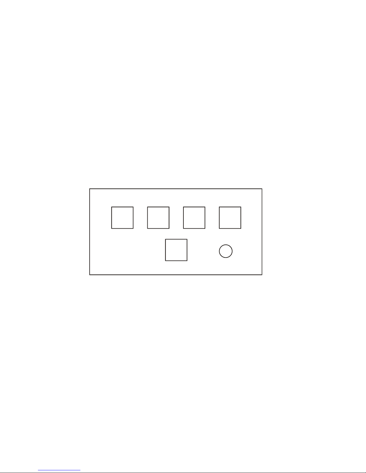
Programming Portion Control (optional)
L.E.D.
CANCEL/POUR
a. Simultaneously, press and hold “S” (small) and “XL” (extra large) push button switches on the Coded
Autoset Portion Control Module until the LED light in the lower right hand corner of the module starts
blinking. Release the switches. The blinking LED indicates the programming mode is active.
b. Place the cup under the white mixing valve nozzle and push the selected size button (small, medium,
large, or extra large). Hold the button in until the cup fills to the desired portion, then release the
button. Repeat the above procedure for the remaining sizes.
c. After programming all the drink sizes, press and release the “cancel/pour” ▲▼ switch to return the
Coded Autoset Portion Control to the operational mode. The blinking LED light will go out.
d. If at a future date, it is decided to change the portion size of the drinks, the individual sizes can be
adjusted by the above procedure. It is not necessary to reprogram every size.
NOTE: The portion control has a full memory retention in case of a power failure.
SMALL
S
MEDIUM
M
LARGE
L
EXTRA-LARGE
XL
▲▼
CANCEL/POUR ▲▼:
a. Push and release cancel/pour button to stop the valve from dispensing.
b. Push and hold for a continuous pour.
6

NOTES:
7

• A small brush
Brixing Concentrate
The following procedures describe how to adjust
the water to concentrate ratio (brix) according to
taste. Contact your concentrate supplier for
recommended brix ratios.
c. Remove the flavor strip cover above the
dispense valves.
d. Sample the finished drink. Increase or
decrease the water ratio by turning the water
flow control screw clockwise (more water) or
counterclockwise (less water) until the desired
water to concentrate ratio is achieved. Repeat
procedure on remaining valves.
e. Replace the flavor strip cover.
NOTE: If the flow control does not respond
there may be debris caught between the internal
ceramic spool and sleeve. Try dislodging the
debris by pressing the dispense switch several
times or turning the flow control adjustment
screw all the way in and out several times.
Cleaning & Sanitizing the
System
The dispenser must be cleaned and sanitized
after installation and as required by state and
local health departments, or every 3 months
minimum. Your state or local health codes may
require more frequent and extensive sanitizing
procedures.
Cleaning and Sanitizing Equipment
and Supplies:
• Recommended sanitizer/cleaner: Stera-
Sheen® Green Label prepared to ensure 200
ppm of available chlorine ( one 2 oz.
packet/1 gallon (3.8 L) of water = 200 ppm).
Solution temperature should be between 80 F
- 100 F (26.7 C - 37.8 C).
• One clean 5 gallon (19 L) bucket
• Three empty bag in the box bags (to cut
valve fittings off)
Flushing the Concentrate Lines &
Valves:
Cleaning and sanitizing is not required for
potable water circuits. Potable water lines
should remain connected and operational during
the cleaning and sanitizing procedures for juice
circuits.
a. Fill the 5 gallon (19 L) bucket with clean
extremely hot tap water, approximately 140oF
(60oC).
b. Take the three empty bag in the boxes and
remove the bags from the carton. With scissors,
cut the bag valve off of the bag and clean the
valve by rinsing it under hot tap water.
c. Connect the bag valve to the gray bag
connector and submerse the parts in the bucket of
hot water.
d. Depress and hold the dispense button until
the concentrate has been fully purged from the
product lines and valves.
IMPORTANT
Do Not flush more than three valve circuits
simultaneously.
e. Once the concentrate is purged, pulse each
valve for 15 seconds on and then release the
button. Repeat this pulsing for 15 cycles for each
circuit being cleaned .Once the 15 cycles have
been completed, allow each valve to dispense for
3 continuous minutes.
f. Remove the nozzles and static mixers from
the dispenser and rinse them under hot tap water
to remove any remnant of excess concentrate.
Repeat for each circuit to be cleaned.
g. Replace the nozzles and static mixers into
their proper location.
h. Discard any remaining hot water left in the
bucket.
• One clean 1 gallon (3.9 L) container or
bucket
• Clean non-abrasive clothes
8

Cleaning & Sanitizing the
Concentrate Lines & Valves:
i. Disconnect the bag valves from the gray bag
connectors and re-connect the bag connectors to
their appropriate product bags.
a. Prepare 5 gallons (19 L) of Stera-Sheen®
Green Label cleaning and sanitizing solution by
mixing one 2 oz. packet/1 gallon (3.8 L) of
potable water. This will provide enough
sanitizing solution to clean and sanitize all 6
concentrate circuits for most installations.
Installations that have 50 or more feet of
concentrate line may require more sanitizing
solution.
IMPORTANT
Use potable water at 80oF-100oF (26.7 oC-26.7
o
C) to create solution. Water temperatures above
this range will breakdown the chlorine count and
minimize sanitation.
b. Submerse the bag connector and bag valve
assembly into the bucket of sanitizing solution.
c. Depress and hold the dispense button until
sanitizing solution is dispensed through the
mixing valves nozzle.
d. Pulse each valve for 15 seconds on and then
release the button. Repeat this pulsing for 15
cycles for each circuit being sanitized. Once the
15 cycles have been completed, allow the
sanitizing solution to stand in the product lines
and valves for 30 minutes.
e. While waiting, remove the nozzles and static
mixers and place them into a separate container
with 2 qts. (1.9 L) of sanitizing solution. Agitate
vigorously using the small brush to remove any
excess concentrate. Allow the parts to soak for
30 minutes.
f. Clean the dispensing valves mixing chamber
with the brush and sanitizing solution (this is the
cavity from which the nozzle is removed).
g. Replace the nozzles and static mixers into
their proper locations and discard the sanitizing
solution used to soak them in.
Note: Do not reuse the sanitizing solution used
to clean the nozzles, static mixers, etc.
h. Activate the dispensing valves for two more
cycles (15 seconds on then off) with sanitizing
solution then run solution continuously through
the dispensing valves for 2 minutes.
j. Depress and hold each dispense button until
juice appears at the outlet of the dispensing
nozzle. Dispense and discard two 8 oz. (237 ml)
cups of juice and verify that there is no chlorine
off taste.
Daily Cleaning and
Maintenance
a. On a daily basis, clean the external cabinet
splash areas using a clean damp cloth. Remove
and wash the cup rest, dispensing nozzles, and
static mixers with clean water. Wipe dry with a
clean soft cloth.
b. Wipe the drip tray in place on the unit, wash
the tray out with a mild soap solution, then rinse
the tray by pouring water down the drip tray’s
drain.
c. Clean all external surfaces of the dispenser
with a sponge and a mild soap solution. Rinse the
sponge out with clean water, then wring the
excess water from the sponge and wipe all
external surfaces of the dispenser.
d. Wipe the dispenser dry with a clean soft
cloth. DO NOT USE ABRASIVE TYPE
CLEANERS. Install the cup rest, dispensing
nozzles, and static mixers on the dispenser.
Maintenance of the
Refrigeration System
Cleaning of the refrigeration components
should be performed by a qualified service
technician.
Continuous maintenance of this dispenser is a
basic requirement for proper operation and
sanitation, including all support equipment
utilized in the daily operation of this equipment.
Cleaning of the Refrigeration
Components:
Disconnect the power before removing the top
bonnet of the dispenser.
9
 Loading...