

Page 1

INSTALLATION MANUAL
Millenium II 4000
Release Date: April 29, 2003
Publication Number: 620919547INS
Revision Date: May 13, 2013
Revision: C
Visit the IMI Cornelius web site at www.cornelius.com for all your Literature needs.
Page 2

The products, technical information, and instructions contained in this manual are subject to change without notice.
These instructions are not intended to cover all details or variations of the equipment, nor to provide for every possible
contingency in the installation, operation or maintenance of this equipment. This manual assumes that the person(s)
working on the equipment have been trained and are skilled in working with electrical, plumbing, pneumatic, and
mechanical equipment. It is assumed that appropriate safety precautions are taken and that all local safety and con
struction requirements are being met, in addition to the information contained in this manual.
This Product is warranted only as provided in Cornelius’ Commercial Warrant applicable to this Product and is subject
to all of the restrictions and limitations contained in the Commercial Warranty.
Cornelius will not be responsible for any repair, replacement or other service required by or loss or damage resulting
from any of the following occurrences, including but not limited to, (1) other than normal and proper use and normal
service conditions with respect to the Product, (2) improper voltage, (3) inadequate wiring, (4) abuse, (5) accident, (6)
alteration, (7) misuse, (8) neglect, (9) unauthorized repair or the failure to utilize suitably qualified and trained persons
to perform service and/or repair of the Product, (10) improper cleaning, (11) failure to follow installation, operating,
cleaning or maintenance instructions, (12) use of “non-authorized” parts (i.e., parts that are not 100% compatible with
the Product) which use voids the entire warranty, (13) Product parts in contact with water or the product dispensed
which are adversely impacted by changes in liquid scale or chemical composition.
Contact Information:
To inquire about current revisions of this and other documentation or for assistance with any Cornelius product contact:
www.cornelius.com
800-238-3600
-
Trademarks and Copyrights:
This document contains proprietary information and it may not be reproduced in any way without permission from
Cornelius.
This document contains the original instructions for the unit described.
IMI CORNELIUS INC
101 Regency Drive
Glendale Heights, IL
Tel: + 1 800-238-3600
Printed in U.S.A.
Page 3

TABLE OF CONTENTS
Safety Instructions . . . . . . . . . . . . . . . . . . . . . . . . . . . . . . . . . . . . . . . . . . . . . . . . . . . . . . . . . . . . . . . . 1
Read and Follow ALL Safety Instructions . . . . . . . . . . . . . . . . . . . . . . . . . . . . . . . . . . . . . . . . . . . . . 1
Safety Overview . . . . . . . . . . . . . . . . . . . . . . . . . . . . . . . . . . . . . . . . . . . . . . . . . . . . . . . . . . . . . 1
Recognition . . . . . . . . . . . . . . . . . . . . . . . . . . . . . . . . . . . . . . . . . . . . . . . . . . . . . . . . . . . . . . . . . 1
Different Types of Alerts . . . . . . . . . . . . . . . . . . . . . . . . . . . . . . . . . . . . . . . . . . . . . . . . . . . . . . . . . . 1
Safety Tips . . . . . . . . . . . . . . . . . . . . . . . . . . . . . . . . . . . . . . . . . . . . . . . . . . . . . . . . . . . . . . . . . . . . 1
Qualified Service Personnel . . . . . . . . . . . . . . . . . . . . . . . . . . . . . . . . . . . . . . . . . . . . . . . . . . . . . . . 1
Safety Precautions . . . . . . . . . . . . . . . . . . . . . . . . . . . . . . . . . . . . . . . . . . . . . . . . . . . . . . . . . . . . . . 2
Shipping And Storage . . . . . . . . . . . . . . . . . . . . . . . . . . . . . . . . . . . . . . . . . . . . . . . . . . . . . . . . . . . . 2
General Information . . . . . . . . . . . . . . . . . . . . . . . . . . . . . . . . . . . . . . . . . . . . . . . . . . . . . . . . . . . . . . . 3
Unit Specifications . . . . . . . . . . . . . . . . . . . . . . . . . . . . . . . . . . . . . . . . . . . . . . . . . . . . . . . . . . . . . . 3
Installation . . . . . . . . . . . . . . . . . . . . . . . . . . . . . . . . . . . . . . . . . . . . . . . . . . . . . . . . . . . . . . . . . . . . . . . 4
Receiving & Unpacking . . . . . . . . . . . . . . . . . . . . . . . . . . . . . . . . . . . . . . . . . . . . . . . . . . . . . . . . . . . 4
Installation . . . . . . . . . . . . . . . . . . . . . . . . . . . . . . . . . . . . . . . . . . . . . . . . . . . . . . . . . . . . . . . . . . . . . 4
Installation Kit P/N 629087474 . . . . . . . . . . . . . . . . . . . . . . . . . . . . . . . . . . . . . . . . . . . . . . . . . . . . . 4
Cleaning & Sanitizing . . . . . . . . . . . . . . . . . . . . . . . . . . . . . . . . . . . . . . . . . . . . . . . . . . . . . . . . . . . . . . 8
Cleaning & Sanitizing the System . . . . . . . . . . . . . . . . . . . . . . . . . . . . . . . . . . . . . . . . . . . . . . . . . . . 8
Daily Cleaning & Maintenance . . . . . . . . . . . . . . . . . . . . . . . . . . . . . . . . . . . . . . . . . . . . . . . . . . . . . 9
Maintenance of the Refrigeration System . . . . . . . . . . . . . . . . . . . . . . . . . . . . . . . . . . . . . . . . . . . . . 9
Panel Removal . . . . . . . . . . . . . . . . . . . . . . . . . . . . . . . . . . . . . . . . . . . . . . . . . . . . . . . . . . . . . . . . . . 11
Page 4
Millennium II 4000 Installation Manual
!
DANGER:
!
WARNING:
CAUTION:
!
!
WARNING:
!
SAFETY INSTRUCTIONS
READ AND FOLLOW ALL SAFETY INSTRUCTIONS
Safety Overview
• Read and follow ALL SAFETY INSTRUCTIONS in this manual and any warning/caution labels on the unit (decals, labels or
laminated cards).
• Read and understand ALL applicable OSHA (Occupational Safety and Health Administration) safety regulations before
operating this unit.
Recognition
Recognize Safety Alerts
This is the safety alert symbol. When you see it in this manual or on the unit,
be alert to the potential of personal injury or damage to the unit.
DIFFERENT TYPES OF ALERTS
Indicates an immediate hazardous situation which if not avoided WILL result in serious injury, death or equipment
damage.
Indicates a potentially hazardous situation which, if not avoided, COULD result in serious injury, death, or equipment
damage.
Indicates a potentially hazardous situation which, if not avoided, MAY result in minor or moderate injury or equipment
damage.
SAFETY TIPS
• Carefully read and follow all safety messages in this manual and safety signs on the unit.
• Keep safety signs in good condition and replace missing or damaged items.
• Learn how to operate the unit and how to use the controls properly.
• Do not let anyone operate the unit without proper training. This appliance is not intended for use by very young children or
infirm persons without supervision. Young children should be supervised to ensure that they do not play with the appliance.
• Keep your unit in proper working condition and do not allow unauthorized modifications to the unit.
QUALIFIED SERVICE PERSONNEL
Only trained and certified electrical, plumbing and refrigeration technicians should service this unit. ALL WIRING
AND PLUMBING MUST CONFORM TO NATIONAL AND LOCAL CODES. FAILURE TO COMPLY COULD
RESULT IN SERIOUS INJURY, DEATH OR EQUIPMENT DAMAGE.
© 2003-2013, IMI Cornelius Inc. - 1 - Publication Number: 620919547INS
Page 5
Millennium II 4000 Installation Manual
!
WARNING:
CAUTION:
!
CAUTION:
!
SAFETY PRECAUTIONS
This unit has been specifically designed to provide protection against personal injury. To ensure continued protection
observe the following:
Disconnect power to the unit before servicing following all lock out/tag out procedures established by the user. Verify
all of the power is off to the unit before any work is performed.
Failure to disconnect the power could result in serious injury, death or equipment damage.
Always be sure to keep area around the unit clean and free of clutter. Failure to keep this area clean may result in
injury or equipment damage.
SHIPPING AND STORAGE
Before shipping, storing, or relocating the unit, the unit must be sanitized and all sanitizing solution must be drained
from the system. A freezing ambient environment will cause residual sanitizing solution or water remaining inside the
unit to freeze resulting in damage to internal components.
Publication Number: 620919547INS - 2 - © 2003-2013, IMI Cornelius Inc.
Page 6
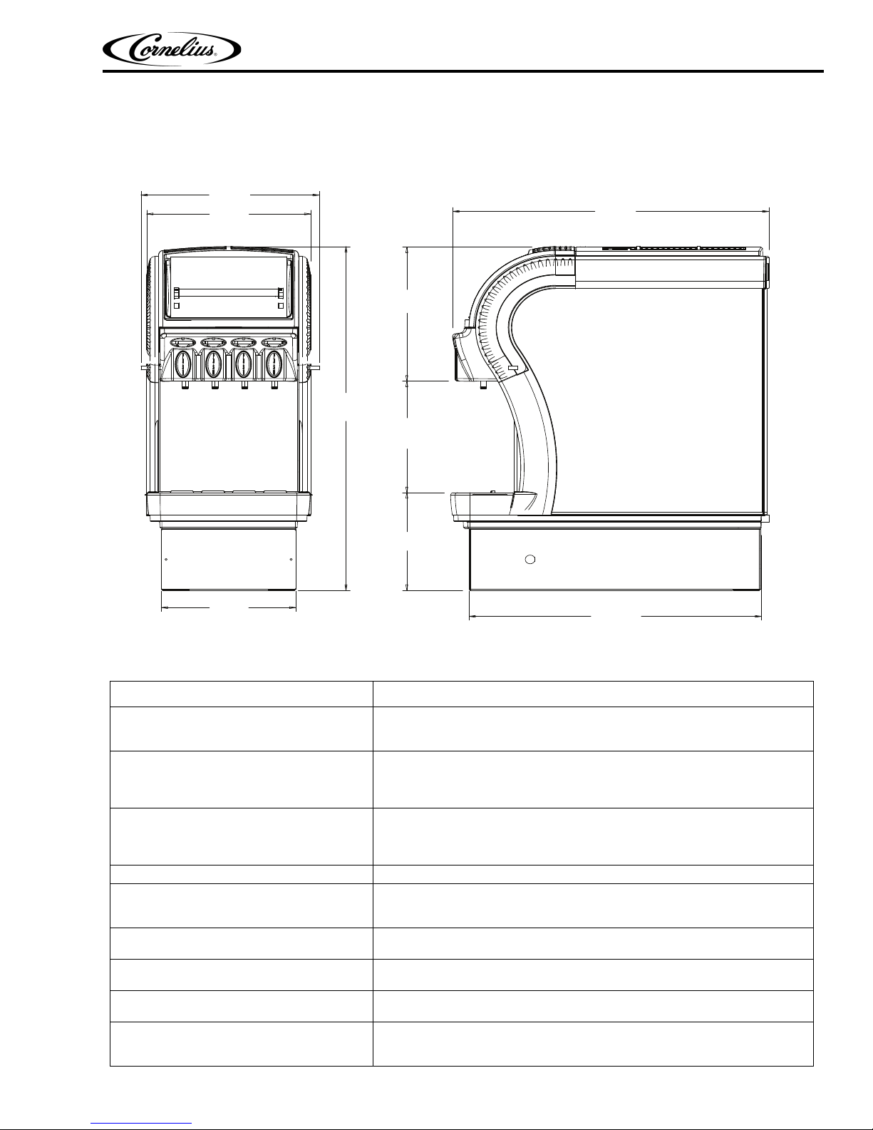
GENERAL INFORMATION
14.750
(374,65)
13.576
(344,84)
31.991
(812,57)
11.124
(282,55)
24.194
(614,53)
9.090
(230.89)
10.381
(263,66)
12.480
(316,98)
26.161
(664,49)
UNIT SPECIFICATIONS
Millennium II 4000 Installation Manual
Figure 1.
Electrical Ratings: 115 VAC / 1 Phase / 60HZ / 11.1 Amps
Model Number Millennium II 4000
230 VAC / 1 Phase / 60HZ / 5.50 Amps
230 VAC / 1 Phase / 50HZ / 6.0 Amps
Electrical Connection: 115V 3 Prong Plug with Ground (supplied)
230V 2 Prong Plug (supplied)
15 Amp Receptacle with Ground
15 Amp Circuit Breaker
Water Requirements: 3/8 (9.5 mm) SAE Male Flare Inlet
Minimum 20 psig (1.4 Bar)
Recommended 40 psig (2.8 Bar)
Maximum 60 psig (4.14 Bar)
Refrigeration: 5.5 oz. (198.4 g) R-134A Refrigerant, 1/3+ HP Compressor
Test Pressures: High: 230 psig (15.8 Bar)
Recommended Clearance: 18 in. (46 cm) Above Dispenser
Low: 90 psig (6.2 Bar)
Air Cooled Condenser
6 in. (16 cm) At Side Panel Vents
Weight: Shipping: 140 lbs. (63.5 kg)
Operating: 220 lbs. (100 kg)
Concentrate Supply Line Length: 50 feet (15.2 m) Total Maximum
15 feet (4.5 m) Vertical Maximum
Approvals: UL
CUL
NSF
© 2003-2013, IMI Cornelius Inc. - 3 - Publication Number: 620919547INS
Page 7

Millennium II 4000 Installation Manual
INSTALLATION
RECEIVING & UNPACKING
1. Inspect the carton and note any damage, regardless if it appears minor. If the carton is damaged, note on the
consignee copy of the freight invoice “exterior carton damage – concealed damage possible”.
2. Cut the banding strap and remove the exterior carton sleeve, internal fillers and plastic bag around the dispenser. Carefully inspect for damage.
NOTE: IMI Cornelius is not responsible for damaged freight. If damage is found, you must save all
packaging material and contact the freight carrier. Failure to contact the carrier within 48 hours of
receipt may void your claim.
INSTALLATION
1. Typically the dispenser is placed directly on the counter and a food grade silicone sealant is applied around the
base. However, the legs that are included with the dispenser may be used. The following instructions assume
the legs will not be used.
2. Depending on the type of counter, it may be necessary to provide access through the counter at the rear of the
dispenser for the drain, power, water and concentrate connections.
INSTALLATION KIT P/N 629087474
Item Part Number Description Qty.
1 300423000 Connector Bag-N-Box 375 4
2 31525016 O-Ring 614ID 070CS 1
3 50119 Hose Plastic 5/8ID X 1/8 Wall 5 ft.
4 70339 Clamp Hose 1
5 620919547INS Manual Installation Millennium 4V 1
6 620920205 thru 10 Flavor Strip Assorted #1 thru #6 6
3. With the assistance of another person, lift the dispenser using the base and place it on the counter.
NOTE: The dispenser is extremely heavy when operational. Make certain the counter can support a
minimum of 300 lbs. directly below the dispenser.
4. Sanitizing Prior to Initial Use
The beverage system must be cleaned and sanitized after installation is completed to safeguard against any possible contaminants that may have entered the system during transport or installation. Refer to the “Cleaning and
Sanitizing the System” section of this manual for procedures.
5. Connecting the Water Supply
A. Water Pipe Connections and fixtures directly connected to a potable water supply shall be sized, installed
and maintained according to federal, state and local laws.
B. It is recommended that a 1/2” OD copper supply line with a shut–off valve and water filter be located within
3–6 feet (0.9–1.8 m) of the dispenser.
C. Remove the splash panel. Run the water supply line through the hole in the back of the base marked
“water” and up the front of the unit to the water inlet fitting located behind the splash panel.
D. Connect the 3.8” ID supply line to water supply with a 3/8” barb fitting.
E. When installing the splash panel, attach the ground wire, at the water bath front, to the splash panel
grounding tab.
NOTE: The dynamic water pressure must be 20 psig (1.3 Bar) minimum to ensure correct valve flow
control and must not exceed 100 psig to avoid valve damage.
Publication Number: 620919547INS - 4 - © 2003-2013, IMI Cornelius Inc.
Page 8

Millennium II 4000 Installation Manual
RedLED
GreenLED
6. Filling the Ice Water Bath
A. Remove the top panel and locate the filler hole in the top of the refrigeration deck.
B. Fill the water bath with cool water until it begins to trickle out of the overflow tube and into the drip tray. Use
tap water. Do Not use distilled water as it’s purity has very low electrical conductivity. This can degrade
performance of the electronic ice bank control.
C. Re-install the top panel.
7. Connecting Power Supply & Starting Refrigeration
A. Plug the power cord into a 115VAC 15 Amp grounded receptacle.
B. Place the rocker switch and key switch, both located on the top panel, to the “on” position. Note that the
rocker switch controls power to the dispenser and the key switch controls the pumps and valves.
C. The Millennium forms an ice bank of approximately 14 lbs. (6.4 kg) in about 5 hours at a room temperature
of 75°F (24°C). Once the ice bank has grown to the proper size, the ice bank control will shut down the
refrigeration circuit.
D. The ice bank control operates the compressor and condenser fan motor to control the size of the ice bank.
The control board will not start or restart the compressor until after the compressor has been off for at least
3 minutes to allow refrigeration system pressure to equalize.
NOTE: It is normal to see water trickle from the overflow as the ice bank forms.
8. Electronic Control Board Function
An integrated circuit board and microprocessor are used to control the electrical functions of the Millennium beverage dispenser. Functional features of the control board include:
• Ice bank control with compressor start-up protection
LED diagnostics
•
Inputs to the control board include line power and the ice bank position sensor. Switche
d outputs from the circuit
board include the compressor, agitator motor and condenser fan motor (refer to electrical diagram in reference section).
9. Ice Bank Control
The ice bank control operates the compressor and condenser fan motor to control the size of the ice bank. The
trol board will not restart the compressor until after the compressor has been off for at least 3 minutes to allow
con
the refrigeration system pressures to equalize.
10. LED Diagnostics
LED diagnostic lights are mounted on the control board to assist in troubleshooting. There is one green LED and
ne red LED.
o
© 2003-2013, IMI Cornelius Inc. - 5 - Publication Number: 620919547INS
Page 9

Millennium II 4000 Installation Manual
Figure 2.
Functions of the LEDs are:
• Red and Green OFF = no power to the dispenser
• Green ON = line voltage is within acceptable range
11. Connecting the Drain
A. Remove the drip tray from the dispenser and drill out the stem with a 7/16” (11 mm) drill bit.
B. Route one end of the 5/8” (15.8 mm) ID hose through the hole in the back of the dispenser marked “drain”
and up to the drip tray fitting located on the dispenser under the drip tray.
C. Attach the hose to the drip tray fitting on the dispenser.
D. Connect the other end of the hose to a suitable drain source, ensuring compliance with all federal, state
and local codes.
E. Slide the drip tray back into place.
12. Purging Air from the Water Coil
A. Prior to initial use, purge all air from the valves by pushing the dispensing switch repeatedly. Continue until
a steady flow of water is observed.
B. Repeat for the remaining valves.
NOTE: Splashing may occur during the purge cycle.
13. Programming the Portion Control
A. If the dispenser comes equipped with the optional Portion Control feature, they have been
pre-programmed from the factory to pour 7, 12 and 16–ounce drinks. The extra large
(pitcher icon) size has also been pre-programmed to pour 16 ounces. To change the pour
sizes, please follow the instructions below:
1. Simultaneously press and hold the “small” and “extra large” push button switches on
the Portion Control Module until the “refill” light starts blinking. Release the switches.
The blinking refill light indicates the programming mode is active.
2. Place the cup under the dispense nozzle and push the selected size button (small,
medium, large or extra large). Hold the button until the cup fills to the desired portion, then release the
button. Repeat the above procedure for the remaining sizes.
3. After programming all the drink sizes, press and release the “cancel/pour” switch to return the Portion
Control to the operational mode. The blinking refill light will go out.
B. If in future it is decided to change the portion size of the drinks, the individual sizes can be adjusted follow-
ing the above procedure. It is not necessary to reprogram every size. Additionally, the Portion Control has
full memory retention in case of a power failure.
C. To pour a drink without using a pre–programmed Portion Control size, simply push and hold the “cancel/
pour” button and release when the cup is full.
14. Connecting the Concentrate & Priming the Pumps
A. Connect the 3/8” barb fittings to the BIB supply line.
NOTE: DO NOT cut any of the lines coming from the rear of the dispenser. The excess slack is
needed to be able to slide the pump platform out of the front of the base for maintenance access.
B. Route the concentrate supply lines to the BIB location and attach the supplied plastic BIB connector to the
end of each line with the clamps provided.
C. Turn off the water supply and connect the concentrate lines to their respective BIB.
D. Depress and hold each start button until concentrate is observed flowing from the nozzle.
E. Turn on the water supply.
Publication Number: 620919547INS - 6 - © 2003-2013, IMI Cornelius Inc.
Page 10

Millennium II 4000 Installation Manual
15. Apply Sealant to Base and Countertop
If the legs supplied with the dispenser are not used to raise the dispenser off the counter, the entire perimeter of the
base must be sealed at the countertop with silicone (or other food grade approved sealant) in order to comply with
NSF standards.
16. Brixing Concentrate
The following procedures describe how to adjust the water to concentrate ratio (brix) according to taste. Contact
the concentrate supplier for recommended brix ratios.
Unit comes with a water coil for dispensing water only. The push button valve to actuate is located on the left side of
the valve panel. Water solenoid assembly to control flow rate is mounted on the syrup pump platform. The flow rate
can be adjusted by turning adjusting screw on the regulator. Turning screw clockwise increases flow rate, turning
counter-clockwise reduces flow rate.
A. Remove the flavor strips above the dispense valves.
B. Sample the finished drink. Increase or decrease the water ratio by inserting a flat blade screwdriver into the
slot behind the flavor label and turning the water flow control screw clockwise (more water) or counter–
clockwise (less water) until the desired water to concentrate ratio is achieved. Repeat the procedure on the
remaining valves.
C. Replace the flavor strips.
NOTE: If the flow control does not respond, there may be debris caught between the internal
ceramic spool and sleeve. Try dislodging the debris by pressing the dispense switch several times
or by turning the flow control adjustment screw all the way in and out several times.
© 2003-2013, IMI Cornelius Inc. - 7 - Publication Number: 620919547INS
Page 11

Millennium II 4000 Installation Manual
CLEANING & SANITIZING
CLEANING & SANITIZING THE SYSTEM
The dispenser must be cleaned and sanitized after installation and as required by state and local health departments or every three months minimum. The state and local health codes may require more frequent and extensive
sanitizing procedures.
1. Cleaning and Sanitizing Equipment and Supplies
A. Stera–Sheen Green Label (or equivalent) prepared to ensure 100ppm of available chlorine (one 1 ounce
packet in one gallon (3.8 l) of water = 100ppm). Solution temperature should be between 80°F and 100°F
(26.7°C and 37.8°C).
NOTE: Use potable water at the temperatures listed above. Water above this range will break down
the chlorine count and minimize sanitation.
B. One clean 5 gallon (19 l) bucket
C. One clean 1 gallon (3.8 l) bucket
D. Clean, nonabrasive towels/rags
E. A small brush with nylon bristles
F. Three valve fittings cut from three empty BIB bags.
2. Flushing the Concentrate Lines and Valves
A. Cleaning and sanitizing is not required for the potable water circuits. Potable water lines should remain
connected and operational during the cleaning and sanitizing of the juice circuits.
B. Fill the 5 gallon (19 l) bucket with clean, extremely hot tap water, approximately 140°F (60°C).
C. Clean the three valve fittings that were cut from the BIB bags by rinsing them under hot tap water.
D. Connect the bag valve to the bag connector coming from the dispenser and submerse the parts in the
bucket of hot water.
E. Press and hold the dispense button until the concentrate has been fully purged from the product lines and
valves.
NOTE: DO NOT flush more than three valves simultaneously.
F. Once the concentrate is purged, pulse each valve for 15 seconds on then release the button. Repeat this
pulsing for 15 cycles for each circuit being cleaned. Once the 15 cycles have been completed, allow each
valve to dispense for 3 continuous minutes.
G. Remove the nozzle and static mixer from the dispenser and rinse them under hot tap water to remove any
excess concentrate. Repeat for each circuit.
H. Replace the nozzles and static mixers into their proper location.
I. Discard any remaining hot water left in the bucket.
3. Cleaning and Sanitizing the Concentrate lines and Valves
A. Prepare 5 gallons (19 l) of Stera–Sheen Green Label cleaning and sanitizing solution (or equivalent) by
mixing one 1 ounce packet per 1 gallon (3.8 l) of potable water. This will provide enough sanitizing solution
to clean and sanitize all 6 concentrate circuits for most installations. Installations that have 50 or more feet
(not recommended) of concentrate line may require more sanitizing solution.
NOTE: Use potable water between 80
break down the chlorine count and minimize sanitation.
o
F and 100oF (26.7oC and 37.8oC). Water above this range will
B. Submerse the bag connector and bag valve assembly into the bucket of sanitizing solution.
C. Press and hold the dispense button until sanitizing solution is dispensed through the mixing valve nozzle.
Publication Number: 620919547INS - 8 - © 2003-2013, IMI Cornelius Inc.
Page 12

Millennium II 4000 Installation Manual
!
WARNING:
!
WARNING:
D. Pulse each valve for 15 seconds on then release the button. Repeat this pulsing for 15 cycles for each cir-
cuit being sanitized. Once the 15 cycles have been completed, allow the sanitizing solution to stand in the
product lines and valves for 30 minutes.
E. While waiting, remove the nozzles and static mixers and place them into a separate container with 2 quarts
(1.9 l) of sanitizing solution. Agitate vigorously using the small brush to remove any excess concentrate.
Allow the parts to soak for 30 minutes.
F. Clean the dispensing valves mixing chamber (this is the cavity from which the nozzle is removed) with the
brush and sanitizing solution.
G. Replace the nozzles and static mixers into their proper locations and discard the sanitizing solution in
which they were soaked.
NOTE: DO NOT reuse the sanitizing solution used to clean the nozzles and static mixers etc.
H. Activate the dispensing valves for 2 more cycles (15 seconds on and off) with the sanitizing solution then
run the solution continuously through the valves for 2 minutes.
I. Disconnect the bag valves from the bag connectors and reconnect the bag connectors to their appropriate
product bags.
J. Press and hold each dispense button until juice is dispensed from the nozzle. Dispense and discard two 8
ounce (237 ml) cups of juice and verify that there is no chlorine off-taste.
DAILY CLEANING & MAINTENANCE
1. On a daily basis, clean the external cabinet splash areas using a clean damp cloth. Remove and wash the cup
rest, dispensing nozzles and static mixers with clean water. Wipe dry with a clean, soft cloth.
2. Wipe the drip tray in place on the dispenser, wash the tray out with a mild soap solution, and then rinse the tray
by pouring water down the drip tray drain.
3. Clean all external surfaces of the dispenser with a sponge and mild soap solution. Rinse the sponge out with
clean water, then wring the excess water from the sponge and wipe all external surfaces of the dispenser.
4. Wipe the dispenser dry with a clean, soft cloth. Install the cup rest, dispensing nozzles and static mixers on the
dispenser.
NOTE: DO NOT use abrasive type cleaners.
MAINTENANCE OF THE REFRIGERATION SYSTEM
Only trained and certified electrical, plumbing and refrigeration technicians should service this unit.
All wiring and plumbing must conform to national and local codes. Failure to comply could
result in serious injury, death or equipment damage.
1. Continuous maintenance of this dispenser is a basic requirement for proper operation and sanitation, including
all support equipment utilized in the daily operation of this equipment.
2. Cleaning of Refrigeration Components
Disconnect power to the unit before servicing. Follow all lock out/tag out procedures established by the user. Verify all
power is off to the unit before performing any work.
Failure to comply could result in serious injury, death or damage to the equipment.
A. The ventilation grilles and the condenser fins should be cleaned periodically to maintain efficient refrigera-
tion and to avoid compressor failure. The condenser fins can be cleaned with a vacuum cleaner or a soft
bristle brush.
© 2003-2013, IMI Cornelius Inc. - 9 - Publication Number: 620919547INS
Page 13

Millennium II 4000 Installation Manual
B. Clean the exterior surfaces of the compressor, agitator motor, fan motor and fan blade with a damp cloth to
remove accumulated dust.
3. Ice Water Bath Cleaning
A. In order to maintain maximum cooling efficiency, the water bath should be cleaned two to four time annu-
ally, depending on local conditions and/or as required by state and local health departments.
B. A convenient time to do this is at the time the dispenser is being sanitized. To save time, the water bath can
be drained while the dispenser is being sanitized.
C. Remove the cup rest and splash panel to access the water bath drain hose. Remove the cap from the drain
hose and extend the hose to a suitable waste receptacle and allow the water bath to drain.
D. Remove the top, side and rear panels as well as the merchandiser. Unplug the harnesses from the mer-
chandiser and top panel.
E. Disconnect the red, white and blue 12–pin connectors as well as the white 2–pin connector from the elec-
trical box.
NOTE: It will be necessary to melt the ice bank to be able to pull the refrigeration deck up and away
from the dispenser. Warm water may be used to accelerate the melting. In order to prevent ice bank
control damage, DO NOT direct the warm water stream on to the sensing probe of the ice bank control. Never use an ice pick or other instrument to remove ice from the evaporator. Such practice can
result in a punctured refrigerant circuit or damage to the water bath tank.
F. Once the ice bath is sufficiently melted, remove the two hitch pins securing the refrigeration deck to the
water bath tank and lift the deck using the two handles.
G. Prepare 1 gallon (3.8 l) of cleaning and sanitizing solution (see “Sanitizing the Concentrate Lines &
Valves”). Pour the cleaning and sanitizing solution into the water bath and clean the sides and bottom of
the tank, the product coils and associated brackets with a fiber brush.
H. Using the solution in the water bath, the fiber brush and a clean cloth soaked with solution, clean the refrig-
eration deck’s evaporator coils, agitator motor shaft and blade and the ice bank sensing probe.
I. Drain the cleaning and sanitizing solution from the water bath and rinse/flush all the components with clean
water.
J. Re-install the refrigeration deck into the water bath and secure the hitch pins.
K. Plug the connectors into their appropriate receptacles on the electrical box.
L. Fill the water bath with cool potable until water begins to trickle from the overflow tube.
M. Install the top, side and rear panels as well as the merchandiser. Connect the harnesses from the mer-
chandiser and top panel to their appropriate terminals.
N. Plug the dispenser into the electrical outlet and turn the unit on.
Publication Number: 620919547INS - 10 - © 2003-2013, IMI Cornelius Inc.
Page 14

PANEL REMOVAL
1. Loosen the retaining screw on top of the merchandising panel.
Figure 3.
2. Depress the center of the merchandising panel.
Millennium II 4000 Installation Manual
3. Slide the top panel about 1 inch toward the rear of the unit and lift it off.
© 2003-2013, IMI Cornelius Inc. - 11 - Publication Number: 620919547INS
Figure 4.
Page 15

Millennium II 4000 Installation Manual
Figure 5.
4. Disconnect the wires from the key and power switches (black wires - key switch; brown wires - power switch).
Figure 6.
5. Remove the cup rest and drip tray assembly.
6. Remove the splash panel by lifting up and pulling the bottom out.
Publication Number: 620919547INS - 12 - © 2003-2013, IMI Cornelius Inc.
Figure 7.
Page 16

Millennium II 4000 Installation Manual
Figure 8.
7. Slide the side panels forward approximately 2 1/2 inches and lift off. Note: There are 3 locking tabs on the
water tank and 3 on the unit base.
Figure 9. Figure 10. Figure 11.
8. Lift the rear panel up and off.
9. Disconnect the agitator motor wires to remove the merchandiser.
© 2003-2013, IMI Cornelius Inc. - 13 - Publication Number: 620919547INS
Figure 12.
Figure 13.
Page 17

Millennium II 4000 Installation Manual
10. Refrigeration deck removal:
A. Remove the inlet water line from the John Guest fitting on the dual water coil.
B. Remove the John Guest fitting from the dual water coil.
Figure 14.
C. Disconnect all the connectors from the back of the control box.
D. Remove the retaining clips from both sides of the water tank before lifting refrigeration chassis.
E. Lift the refrigeration out of the water bath.
Publication Number: 620919547INS - 14 - © 2003-2013, IMI Cornelius Inc.
Figure 15.
Figure 16.
Page 18

Page 19

IMI Cornelius Inc.
www.cornelius.com
 Loading...