


LANDMARK ICE DISPENSERS
®
Installation and Service Manual
Release Date: June 15, 2004
Publication Number: 60418002
Revision Date: March 21, 2014
Revision: F
Visit the Cornelius web site at www.cornelius.com
for all your Literature needs.

The products, technical information, and instructions contained in this manual are subject to change
without notice. These instructions are not intended to cover all details or variations of the equipment,
nor to provide for every possible contingency in the installation, operation or maintenance of this
equipment. This manual assumes that the person(s) working on the equipment have been trained
and are skilled in working with electrical, plumbing, pneumatic, and mechanical equipment. It is
assumed that appropriate safety precautions are taken and that all local safety and construction
requirements are being met, in addition to the information contained in this manual.
This Product is warranted only as provided in Cornelius’ Commercial Warrant applicable to this Product and is subject to all of the restrictions and limitations contained in the Commercial Warranty.
Cornelius will not be responsible for any repair, replacement or other service required by or loss or
damage resulting from any of the following occurrences, including but not limited to, (1) other than
normal and proper use and normal service conditions with respect to the Product, (2) improper voltage, (3) inadequate wiring, (4) abuse, (5) accident, (6) alteration, (7) misuse, (8) neglect, (9) unauthorized repair or the failure to utilize suitably qualified and trained persons to perform service and/or
repair of the Product, (10) improper cleaning, (11) failure to follow installation, operating, cleaning or
maintenance instructions, (12) use of “non-authorized” parts (i.e., parts that are not 100% compatible
with the Product) which use voids the entire warranty, (13) Product parts in contact with water or the
product dispensed which are adversely impacted by changes in liquid scale or chemical composition.
Contact Information:
To inquire about current revisions of this and other documentation or for assistance with any Cornelius product contact:
www.cornelius.com
800-238-3600
Trademarks and Copyrights:
This document contains proprietary information and it may not be reproduced in any way without permission from Cornelius.
This document contains the original instructions for the unit described.
CORNELIUS INC
101 Regency Drive
Glendale Heights, IL
Tel: + 1 800-238-3600
Printed in U.S.A.

Landmark Ice Dispenser Installation and Service Manual
TABLE OF CONTENTS
General Description . . . . . . . . . . . . . . . . . . . . . . . . . . . . . . . . . . . . . . . . . . . . . . . . . 1
Unpacking and Inspection . . . . . . . . . . . . . . . . . . . . . . . . . . . . . . . . . . . . . . . . . . . . . 1
Location Requirements . . . . . . . . . . . . . . . . . . . . . . . . . . . . . . . . . . . . . . . . . . . . . . . 1
Installing Unit . . . . . . . . . . . . . . . . . . . . . . . . . . . . . . . . . . . . . . . . . . . . . . . . . . . . . . . 1
Ice Gate Adjustment . . . . . . . . . . . . . . . . . . . . . . . . . . . . . . . . . . . . . . . . . . . . . . . . . 3
Cleaning and Maintenance . . . . . . . . . . . . . . . . . . . . . . . . . . . . . . . . . . . . . . . . . . . . 3
Cleaning Equipment and Supplies . . . . . . . . . . . . . . . . . . . . . . . . . . . . . . . . . . . . . . 4
Cleaning and Sanitizing Procedure . . . . . . . . . . . . . . . . . . . . . . . . . . . . . . . . . . . . . . 4
Troubleshooting Guide . . . . . . . . . . . . . . . . . . . . . . . . . . . . . . . . . . . . . . . . . . . . . . . 5
© 2004-2014, Cornelius Inc. - i - Publication Number: 60418002

Landmark Ice Dispenser Installation and Service Manual
Publication Number: 60418002 - ii - © 2004-2014, Cornelius Inc.
IMPORTANT - To the user - This manual is a guide for installing, operating, and maintaining this
equipment. Please read and maintain this document for service and troubleshooting.
GENERAL DESCRIPTION
The LANDMARK Ice Dispenser consists of an ice storage bin and an ice dispensing system.
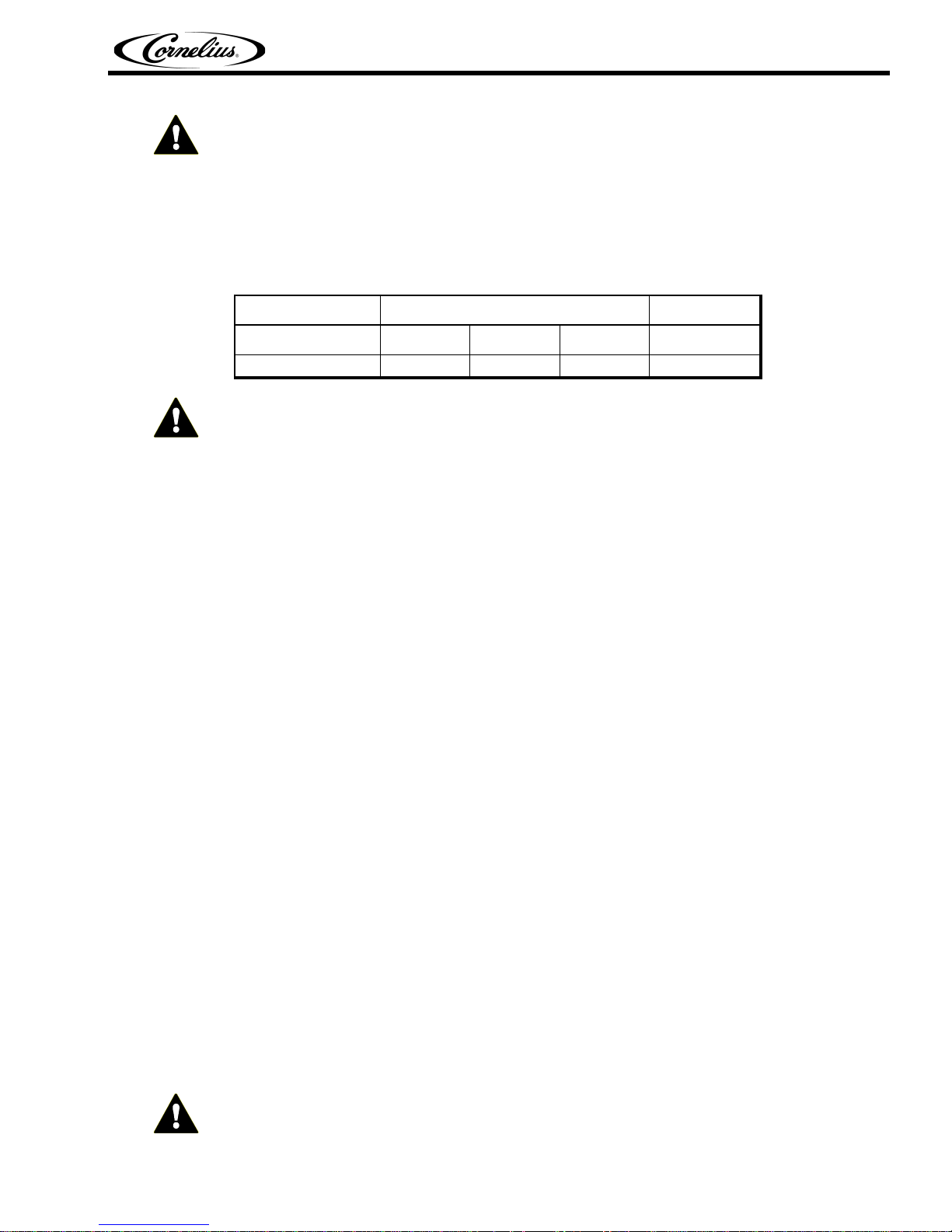
Wilshire LANDMARK ICE DISPENSERS are designed to dispense any type of hard cube ice, up to one
inch square, and will dispense some types of extruded ice. The use of flaked ice and "super cold ice" are
not recommended.
Model Width Depth Height Capacity
ID-90 Series 15.00" 21.00" 34.50" 90#
NOTICE - PRIOR TO ICE MAKER INSTALLATION: Contact Wilshire Customer Service
(800-654-1729) for a top adapter and to verify that the ice maker is compatible with the
LANDMARK. Incompatible cube size and/or installation of an ice maker without the proper top
adapter can cause damage to the dispenser. FAILURE TO COMPLY WITH THESE
REQUIREMENTS WILL VOID THE WARRANTY.
Landmark Ice Dispenser Installation and Service Manual
Cabinet Ice Storage
NOTE: When using extruded ice, the agitator motor timer relay must be bypassed. Refer to wiring
diagram on page 6.
UNPACKING AND INSPECTION
The unit was thoroughly inspected before leaving the factory. Any damage should be noted at the time of
delivery (no later than 15 days from date of delivery) and immediately reported to the carrier. File the
claim with the delivering carrier.
After removal of shipping carton, remove parts from the ice compartment.
LOCATION REQUIREMENTS
Use a separate 120VAC, 60HZ 1PH, 15 AMP grounded duplex outlet to accommodate each dispenser.
Locate the outlet within three (3) feet of the dispenser. Extension cords cannot be used. ALL
ELECTRICAL WIRING MUST CONFORM TO NATIONAL AND LOCAL ELECTRICAL CODES. (See
Wiring Diagrams, FIGURE 1)
The counter must be able to support 250 pounds, which includes dispenser and ice.
INSTALLING UNIT
With the template provided in the installation kit, mark the outline of the Ice Dispenser on the counter
surface and location for drain line. Apply a 1/2 inch wide bead of silastic (such as Dow Corning 732)
within the dispenser outline. Place the Ice Dispenser on top of the silastic. Wipe the excess silastic
creating a smooth seal. All holes cut in counter top for product, drain, and electrical lines must be sealed
with an acceptable material in accordance with local, state health, and building codes.
Attach the drain hose and clamps to the bottom of the drip pan assembly. Connect the unit to a drain
outlet according to state and local requirements.
Place the ice trap in the drain outlet in the ice bin. This holds ice away from drain outlet and allows water
to drain properly.
Check connection for leaks.
IMPORTANT - SYSTEM MUST BE SANITIZED AS INSTRUCTED PRIOR TO OPERATION. See
Cleaning and Sanitizing Instructions.
© 2004-2014, Cornelius Inc. - 1 - Publication Number: 60418002

Landmark Ice Dispenser Installation and Service Manual
FRONT
After all connections are made, system checked for leaks and sanitized, the unit is now ready for
operation.
NOTE: Static Breaker bar in the ice bin MUST BE situated inside the right of the dispense door
(as you face the front of the unit) or no ice will be dispensed and damage to the dispense wheel
mechanism could result. See Figure 1 for proper orientation.
FIGURE 1 Static Bar Location
Publication Number: 60418002 - 2 - © 2004-2014, Cornelius Inc.

ICE GATE ADJUSTMENT
An ice gate is provided to control the dispensed flow rate of ice. The ice gate is mounted on the
positioning tab at the end of the static bar. The ice gate may be adjusted for the type and size of ice being
used. Once set no further adjustments should be necessary.
Prior to adjusting the ice gate position, be sure to disconnect power to the dispenser to prevent the
agitator from rotating while adjusting the ice gate.
Fill bin with ice up to the chute to a depth of approximately 6 inches from the bottom of the bin. With a cup
held below the ice chute, press the ice dispense button or lever. If the flow rate needs adjustment,
disconnect power and remove static bar assembly (see Figure 2). Reposition ice gate to either the fast,
medium, or slow position as shown in Figure 1. Carefully reinstall static bar assembly as described in
Figure 1.
Landmark Ice Dispenser Installation and Service Manual
CLEANING AND MAINTENANCE
The dispenser must be cleaned and sanitized after installation and, thereafter, as required by state
and local health departments, or every three months minimum.
Continuous maintenance of this unit is a basic requirement for proper operation and sanitation, including
all support equipment utilized in the daily operation of this equipment.
FIGURE 2
© 2004-2014, Cornelius Inc. - 3 - Publication Number: 60418002

Landmark Ice Dispenser Installation and Service Manual
CLEANING EQUIPMENT AND SUPPLIES
• Recommended cleaner: A. C. Fergusson Company #3391 or any caustic-base (low sudsing, nonperfumed, easily rinsed) detergent solution which provides a minimum 2% sodium hydroxide. The
solution should be prepared in accordance with the manufacturer's instructions. Solution temperature
should be between 90 to 110° F. Temperatures in excess of this can cause internal damage to the
dispensing valve components.
• Recommended sanitizer: A. C. Fergusson Company SuperChlor or any sanitizer which provides a
minimum of 200 parts per million (200 milligrams per liter) of available chlorine. Solution temperature
should be between 90 to 110° F. Temperatures in excess of this can cause internal damage to the
dispensing valve components.
• Containers for cleaner and sanitizer solutions
• Clean, nonabrasive cloths
• Bucket
• Small Brush
CLEANING AND SANITIZING PROCEDURE
The ice bin should be thoroughly cleaned and sanitized at least once every month or as required by state
and local health departments.
WARNING - When using cleaning fluids or chemicals, rubber gloves and eye protection should be
worn.
1. Disconnect electrical power to dispenser.
2. Remove manual ice fill lid.
3. Remove the ice chute.
4. Remove dispense wheel by lifting out of bin.
5. Using a soft brush, wash down the sides of the ice bin and the surface of the aluminum cold plate
and motor shaft with cleaning solution.
6. Thoroughly rinse the cleaning solution from the ice bin.
7. Using a soft brush and sanitizing solution, thoroughly brush all surfaces.
8. Using a soft brush and cleaning solution, wipe all ice bin components and rinse thoroughly.
9. Using a soft brush and sanitizing solution, and taking parts in order of replacement in bin,
thoroughly brush all parts and reinstall them in ice bin.
10. Connect electrical power to dispenser and refill with ice.
NOTE: Static Breaker bar in the ice bin must be situated inside the right of the dispense door or
no ice will be dispensed.
Publication Number: 60418002 - 4 - © 2004-2014, Cornelius Inc.

TROUBLESHOOTING GUIDE
The following is provided to aid in correcting ice dispensing system problems. Refer to individual
accessory manuals for troubleshooting help for other components.
WARNING - Disconnect electrical power before attempting any repairs.
PROBLEM POSSIBLE CAUSE SOLUTION
Landmark Ice Dispenser Installation and Service Manual
Ice Dispenses Continuously Misaligned door assembly or
Ice Dispenser Door will not
close
Dispenser will not dispense
ice
solenoid
Misaligned micro switch Adjust micro switch
Ice jammed in chute Adjust bridge or when manually
Solenoid plunger dragging or
catching
No Power Check electrical connections.
Solenoid Malfunction Replace solenoid.
Dispenser overloaded with ice Remove ice from dispenser
Motor not working Replace motor or motor start
Stationary bar is not in correct
location
No ice in bin Fill bin with ice. If field installed
Adjust solenoid
filling, break up clusters.
Adjust solenoid.
until unit will operate.
capacitor.
ice maker
in use, turn on or repair.
Excessive Clustering or
Bridging of ice
© 2004-2014, Cornelius Inc. - 5 - Publication Number: 60418002
Gearmotor thermal overload Reset red button underneath
gearmotor.
Loaded ice not broken up Break ice clusters before
manually filling bin.
Extremely low usage of
dispenser
Static Bar not in position Reposition, see Figure 1.
Excessive water spilling from
field installed ice maker
Poorly adjusted field installed
ice maker
Install bin thermostat to lower
ice level.
Adjust ice maker to eliminate
spillage.
Adjust ice maker to eliminate
large waffle shapes.

Landmark Ice Dispenser Installation and Service Manual
PROBLEM POSSIBLE CAUSE SOLUTION
Dispensing Crushed Ice or
Reduced Dispensing Speed
Water spillage from field
installed ice making machine
Adjust ice maker.
Bridge of ice sheet is too thick Adjust field installed ice maker.
Ice clusters in bin Break up clusters.
Irregular Sound Shaved ice clusters in bin Remove clusters.
Publication Number: 60418002 - 6 - © 2004-2014, Cornelius Inc.
FIGURE 3 Wiring Diagram

Landmark Ice Dispenser Installation and Service Manual
FIGURE 4 Wiring Diagram - Timed Agitation
© 2004-2014, Cornelius Inc. - 7 - Publication Number: 60418002

Landmark Ice Dispenser Installation and Service Manual
Publication Number: 60418002 - 8 - © 2004-2014, Cornelius Inc.


Cornelius Inc.
www.cornelius.com
 Loading...