

Page 1

VFCB Operator’s Manual
VFCB
(Visual Frozen Carbonated
Beverage)
Post-Mix and Pre-Mix
Operator’s Manual
Release Date: 20/04/10
Publication Number:
Revision: 8
Pag. : 1/59
Page 2

VFCB Operator’s Manual
VFCB POST-MIX AND PRE-MIX
OPERATOR’S MANUAL
The products, technical information, and instructions contained in this manual are subject
to change without notice. These instructions are not intended to cover all details or variations
of the equipment, nor to provide for every possible contingency in the installation,
operation or maintenance of this equipment. This manual assumes that the person(s)
working on the equipment have been trained and are skilled in working with electrical,
plumbing, pneumatic, and mechanical equipment. It is assumed that appropriate safety
precautions are taken and that all local safety and construction requirements are being
met, in addition to the information contained in this manual.
To inquire about current revisions of this and other documentation or for assistance with
any Cornelius product contact:
www.cornelius.com
1-800-238-3600
This document contains proprietary information and it may not be
reproduced in any way without permission from Cornelius.
Printed in ITALY.
Copyright © 2006, All Rights Reserved, IMI Cornelius Inc.
Release Date: 20/04/10
Publication Number:
Revision: 8
Pag. : 2/59
Page 3

VFCB Operator’s Manual
TABLE OF CONTENTS
IMPORTANT WARNINGS AND ADVICE ..................................................................................4
TECHNICAL DATA ..........................................................................................................................4
TRANSPORTATION INDICATIONS...........................................................................................4
INSTALLATION................................................................................................................................5
CONNECTING THE ELECTRICITY MAINS ..............................................................................6
CONNECTION DIAGRAMS ..........................................................................................................7
BOWL LOADING OPERATIONS .................................................................................................9
PROGRAMMING ELECTRONIC TOUCH PAD .......................................................................12
CONSISTENCY ADJUSTMENT..................................................................................................20
SIX MONTHLY CLEANING AND SANITATION....................................................................21
SPECIAL MAINTENANCE ...........................................................................................................25
ELECTRONIC MONITORING.....................................................................................................28
WIRING DIAGRAM.......................................................................................................................36
TROUBLESHOOTING...................................................................................................................41
PARTS DIAGRAMS.......................................................................................................................45
Release Date: 20/04/10
Publication Number:
Revision: 8
Pag. : 3/59
Page 4
VFCB Operator’s Manual
IMPORTANT WARNINGS AND ADVICE
This instruction manual represents an integral part of the equipment and must be kept readily
available for use. Read the warnings contained herein carefully before installing and using this
equipment. In addition to offering information concerning routine maintenance for the ice slush
drinks machine and technical back-up for troubleshooting, this manual aims to help the user
make the most of the machine’s potential, adapting it to suit the specific needs of the various
countries it will be used in. Modifications or attempts to modify the equipment will not only
result in the forfeiture of the guarantee, but are also extremely dangerous.
The maintenance operations must be carried out by qualified professionals. Never attempt to
repair the machine yourselves as the intervention of non-qualified persons, as well as being
hazardous, could also lead to serious damage to the machine.
ATTENTION: Before starting up the machine it’s necessary to perform all the cleaning
and sanitation procedures.
TECHNICAL DATA
PLATE DATA
The voltage and the frequency are indicated on the serial number plate, located behind the
drip tray and the right hand side near the controls.
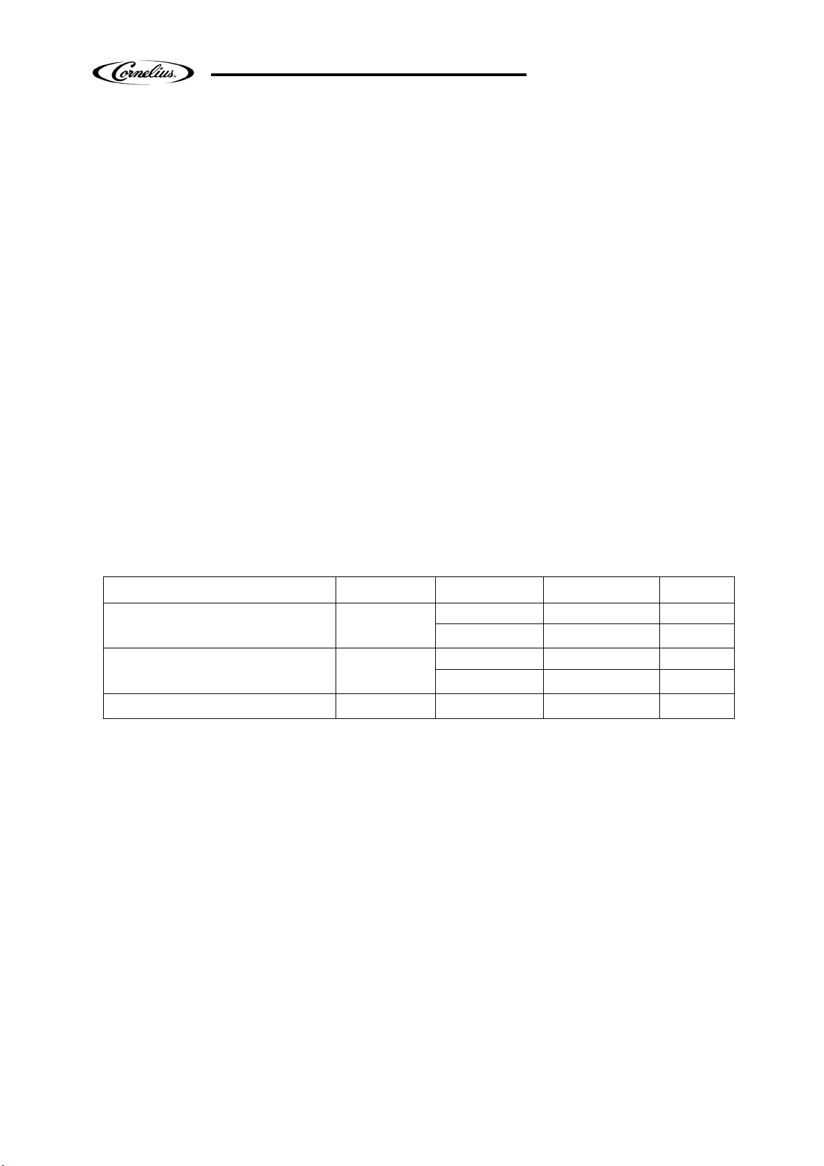
Machine Bowl n° Volt Hertz Ampere
230 50 7.3 VFCB POST MIX 2
115 60 13.8
230 50 7.3 VFCB PRE MIX 2
115 60 13.8
VFCB POST MIX 3 115 60 21.5
IMPORTANT: This machine is intended for use at a maximum ambient temperature of
32°C (90°F).
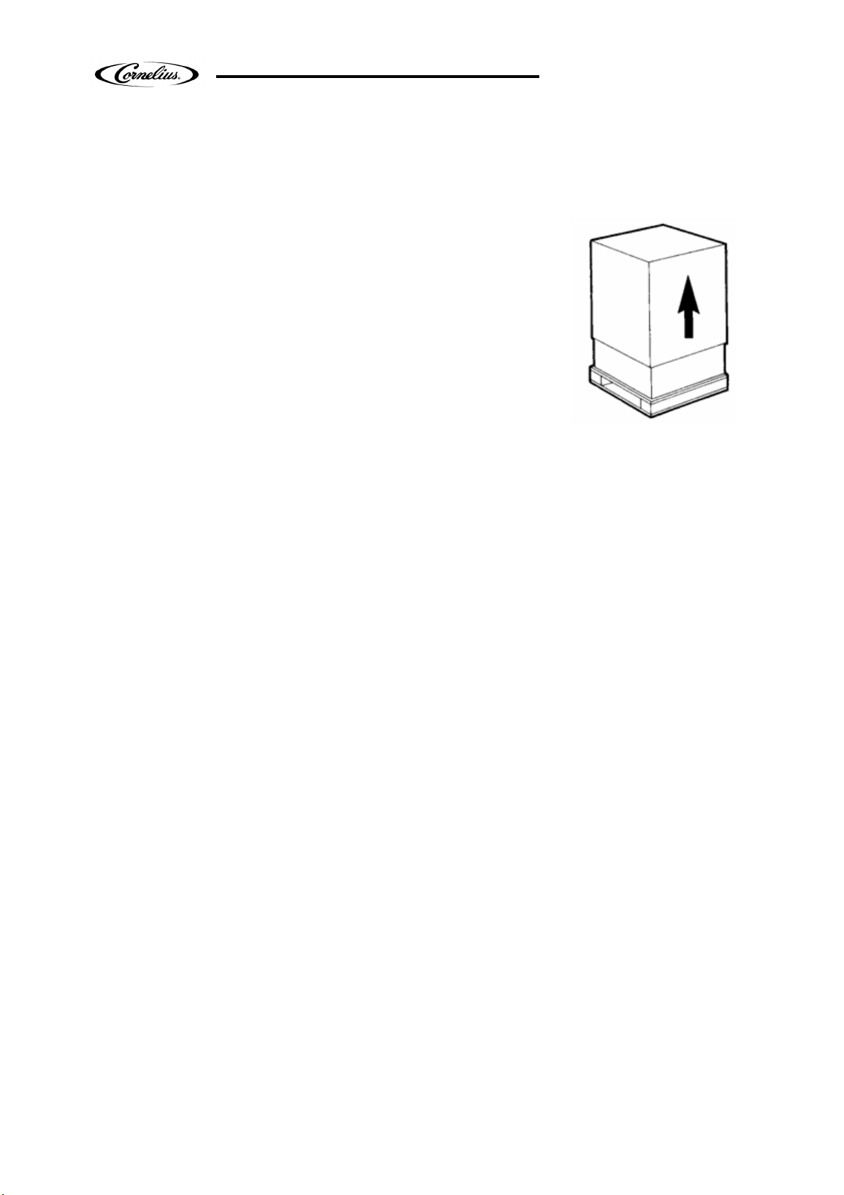
TRANSPORTATION INDICATIONS
To prevent the oil contained in the compressor from flowing out into the cooling circuit, the
equipment must be transported, stored, and handled in a vertical position, as per the
indications given on the packing. The wooden pallet, equipped with housing for the lifting
forks, allows the packed equipment to be moved using normal handling and hoisting means.
Release Date: 20/04/10
Publication Number:
Revision: 8
Pag. : 4/59
Page 5
VFCB Operator’s Manual
INSTALLATION
1. Release the equipment from the packing, then slide it off
upwards (see Fig. 1). The machine has to be installed in level
with horizontal plane;
2. Checking the machine identification after removing the
packing, you must check that the equipment you have
received is exactly as you ordered, making sure the
specifications indicated on the invoice or the delivery note
are identical to those on the data plate.
Fig. 1
3. Equipment accessories
On opening the packing you will find the following accessories inside the bowls:
• this instruction manual;
• 1 tube of Vaseline to be used for the maintenance machine the requires;
• 2 bags, each one containing a drip tray
• 2 evaporator frontal seals
4. Positioning - make sure the machine’s bodywork is well ventilated (20cm (8”) all around at
least ) and do not install it near heat sources.
We recommend you keep the room temperature at between 59°F (15°C) and 90°F (32°C).
IMPORTANT: All the pieces of packing must be kept out of reach of children as they
represent potential hazards.
Release Date: 20/04/10
Publication Number:
Revision: 8
Pag. : 5/59
Page 6
VFCB Operator’s Manual
CONNECTING THE ELECTRICITY MAINS
Before inserting the plug into the mains socket for your own safety you must take careful note
of the following precautions.
• The machine’s electrical system can only be considered
safe when it is connected correctly to an earthing system, as
provided for by the national safety regulations. The manufacturer
cannot be held responsible for any damages that may be caused
by failure to earth the system.
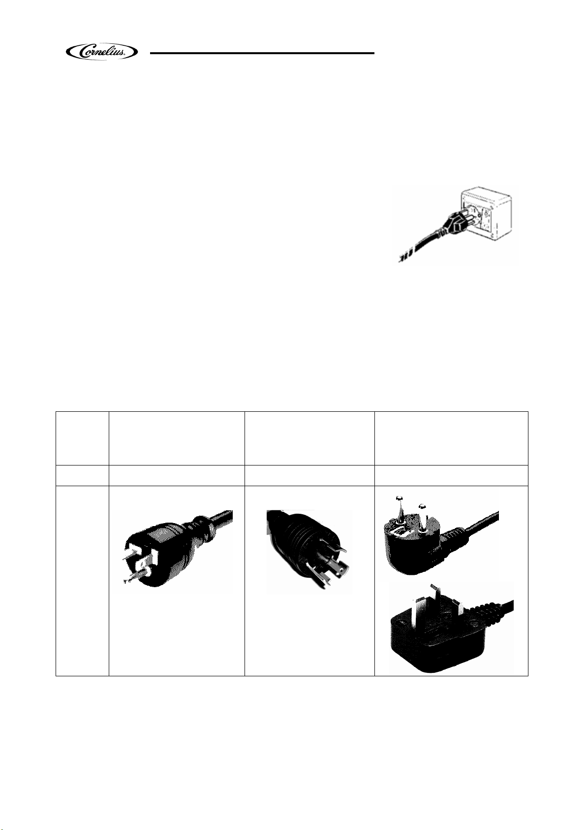
• For the system to be installed correctly and safely, it is
essential to provide a suitable socket which complies with the
national safety standards in force (see Fig. 2).
• Check the length of the power supply cable to make sure it is not being crushed, do not use
extension cables and, to remove the plug, first turn off the switch, then hold the plug tightly
and pull gently.
• Do not obstruct the ventilation and the heat dissipation grids as bad airing, in addition to
reducing the output and causing bad functioning, could also lead to serious damage to the
equipment.
• Plug:
Machine VFCB post mix 115-60
2 bowl
VFCB pre mix 230-50
2 bowl
Fig. 2
VFCB post mix 115-60
3 bowl
VFCB post mix 230-50
2 bowl
VFCB pre mix 230-50
2 bowl
Plug Nema 5-20 Nema L5-30 cs-sd or cs-sa
IMPORTANT: If the power supply cable is damaged, it must be replaced by qualified
persons only, to prevent any possible risks.
Release Date: 20/04/10
Publication Number:
Revision: 8
Pag. : 6/59
Page 7
VFCB Operator’s Manual
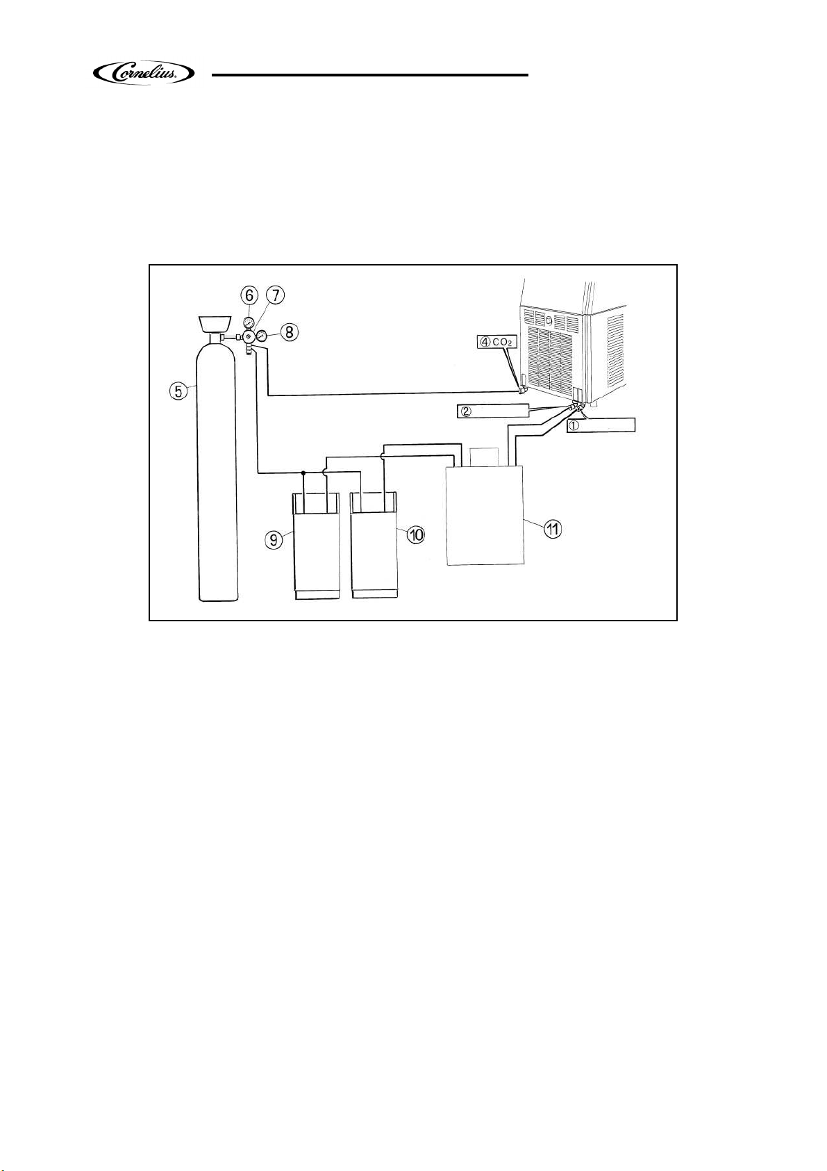
CONNECTION DIAGRAMS
VFCB (PRE-MIX)
The diagram shows the sequence for the connection between the VFCB PRE-MIX to an existing
pre-mix system.
Fig. 3
Description:
(1)Pre-mix product 1 inlet
(2)Pre-mix product 2 inlet
(4)Inlet for CO2 (recommended pressure 21-22 PSI - 1.5 Bar)
(5)CO2 gas cylinder
(6)Operating pressure gauge
(7)CO2 pressure reducing valve
(8)Gas cylinder pressure gauge
(9)Pre-mix product 1 container
(10)Pre-mix product 2 container
(11)Cooling unit
Connection:
Proceed by connecting the points 1, 2, and 4 on the machine to the existing pre-mix system
using quick couplings.
Release Date: 20/04/10
Publication Number:
Revision: 8
Pag. : 7/59
Page 8
VFCB Operator’s Manual
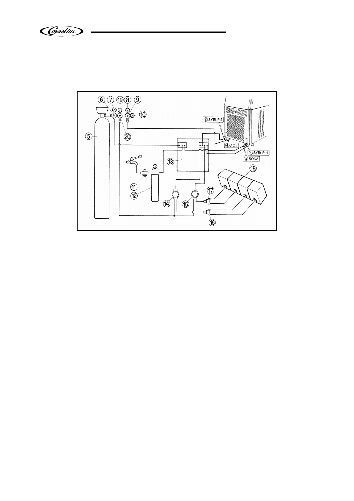
VFCB (POST-MIX)
The diagram shows the sequence for the connection between the VFCB POST-MIX to an
existing post-mix system.
Fig. 4
Description:
(1)Syrup 1 inlet
(2)Syrup 2 inlet
(3)Soda water inlet
(4)Inlet for CO2 (recommended pressure 21-22 PSI - 1.5 Bar)
(5)CO2 gas cylinder
(6)Operating pressure reducing valve for carbonation unit
(7)Carbonation unit operating pressure gauge
(8)Unit Operating pressure gauges
(9)Pressure reducing valve
(10)Gas cylinder operating pressure gauge
(11)Water pressure reducing valve
(12)Filter
(13)Carbonation unit and optional pre-cooling unit
(14)Syrup 1 pump
(15)Syrup 2 pump
(16)Bag-in-box exchanger
(17)Bag-in-box exchanger
(18)Bag-in-box
(19)BIB Operating pressure gauges
(20)Pressure reducing valve
Connection:
Proceed by connecting the points 1, 2, 3, and 4 on the machine to the existing post-mix
system using quick couplings.
Release Date: 20/04/10
Publication Number:
Revision: 8
Pag. : 8/59
Page 9
VFCB Operator’s Manual
BOWL LOADING OPERATIONS
VFCB (PRE-MIX)
• Switch on the machine’s main switch.
• Put the switch (A) into position 1 – Fig. 5 - (switch
A controls the flow of the product in the bowls).
• The machine’s bowls will now fill up until the
maximum level is reached.
• Proceed to start up operations.
VFCB (POST-MIX)
C1
D1
Fig. 5A
Fig. 5
• Loosen the valve flanges screws as indicated in the fig.5A
without disconnecting them from the inferior flange;
• Remove the superior flange (C1) as indicated by the arrow in
the fig.5A;
• Leave the inferior flange (D1) on the bowl surface, it will be
easier to reassemble it after the brixing procedures.
Release Date: 20/04/10
Publication Number:
Revision: 8
Pag. : 9/59
Page 10
VFCB Operator’s Manual
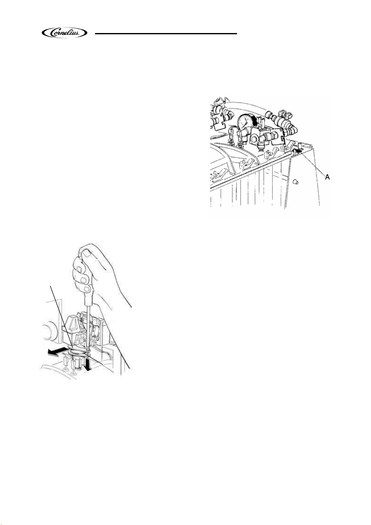
• Switch the machine’s main power switch to the
ON position.
• Make sure the switch (L1) is in the OFF position
(0) – Fig. 6. (Switch L1, A in fig.5, controls the
flow of the products in the bowls)
• Turn mixing motors OFF immediately. Do not
run units with bowls empty
• Using an 8 mm socket wrench (E1), loosen the
nut that holds the post-mix valve (D1).
• Lift the post mix valve (D1) up slightly and turn
it towards the outside. Leaving nozzle (F1) and
coupling attached to the bowl.
D1
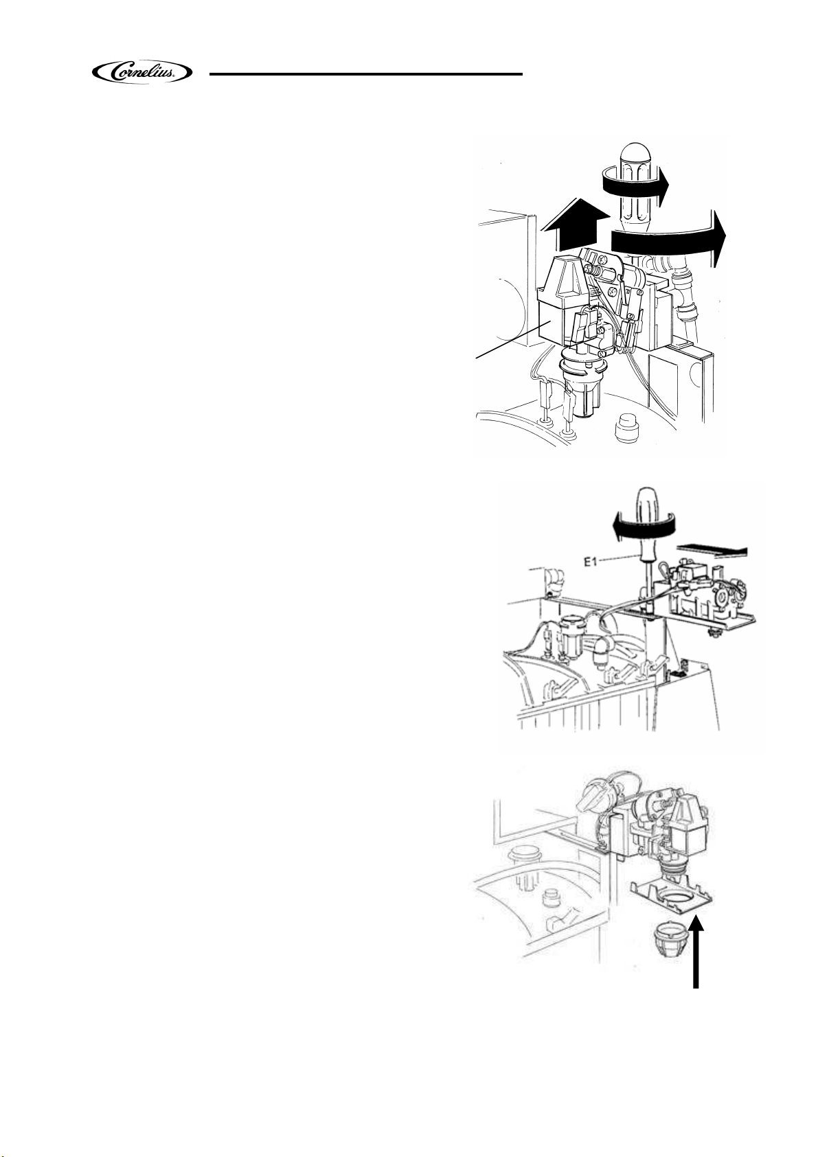
• Now rotate the valve assembly 90 degrees and slide to
the outside of the machine. Tighten the 8mm nut using a
socket wrench (E1) – Fig. 7;
• Assemble the valve plate (A1) and the black knob
(B1) (you can find them inside the machine package)
as indicate in the fig.8;
• If you need to do the brixing procedures using the
calibrator/separator you have to assemble it instead
the black knob;
• Checking and adjusting the water flow is most easily
done by first disconnecting the syrup bib.
Fig. 6
E1
L1
F1
Fig. 7
A1
B1
Fig. 8
Release Date: 20/04/10
Publication Number:
Revision: 8
Pag. : 10/59
Page 11
VFCB Operator’s Manual
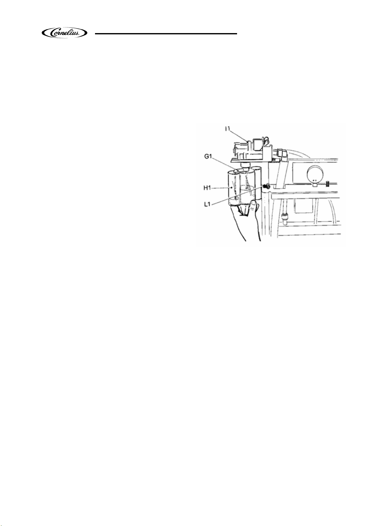
•
If necessary apply the calibrator/separator relative measuring cup (H1) and push the button
(or the micro switch) on the valve (l 1) until both the soda water and the syrup run into the
measuring cup separately (Fig. 9).
•
Adjust the water flow to the minimum level in order to reduce the inlet pressure. Turn the
water adjustment screw on the flow control counter clockwise until the minimum position to
decrease water flow (clockwise to increase it).
•
Reconnect the syrup.
•
Dispense product into a cup or into the
measuring cup by depressing the micro switch
on the valve. Check brix using a refractometer or
the measuring cup. The brix should be set to
13% ± 1%. To increase the brix adjust the syrup
adjustment screw on the valve clockwise to
increase syrup flow or counter clockwise to
decrease syrup flow.
CAUTION: Do not turn the syrup flow
control counter clockwise to far .
•
When the brix has been set to specification,
reposition the valve to its original setting &
tighten retaining nuts.
•
Repeat the operation for the second bowl.
•
Once the adjustments have been completed for each bowl, place the switch (L1) in the “ON”
position.
•
Both bowls will fill until the level sensor is activated.
•
Turn mixing motors “ON” (switch located on the control panel). The dispenser has built in
delays for compressor & bowl fill switch.
•
NOTE: During initial filling it is normal for some foaming to take place. The bowl level
management will adjust as the product freezes & the foam will dissipate.
Fig. 9
Release Date: 20/04/10
Publication Number:
Revision: 8
Pag. : 11/59
Page 12
VFCB Operator’s Manual
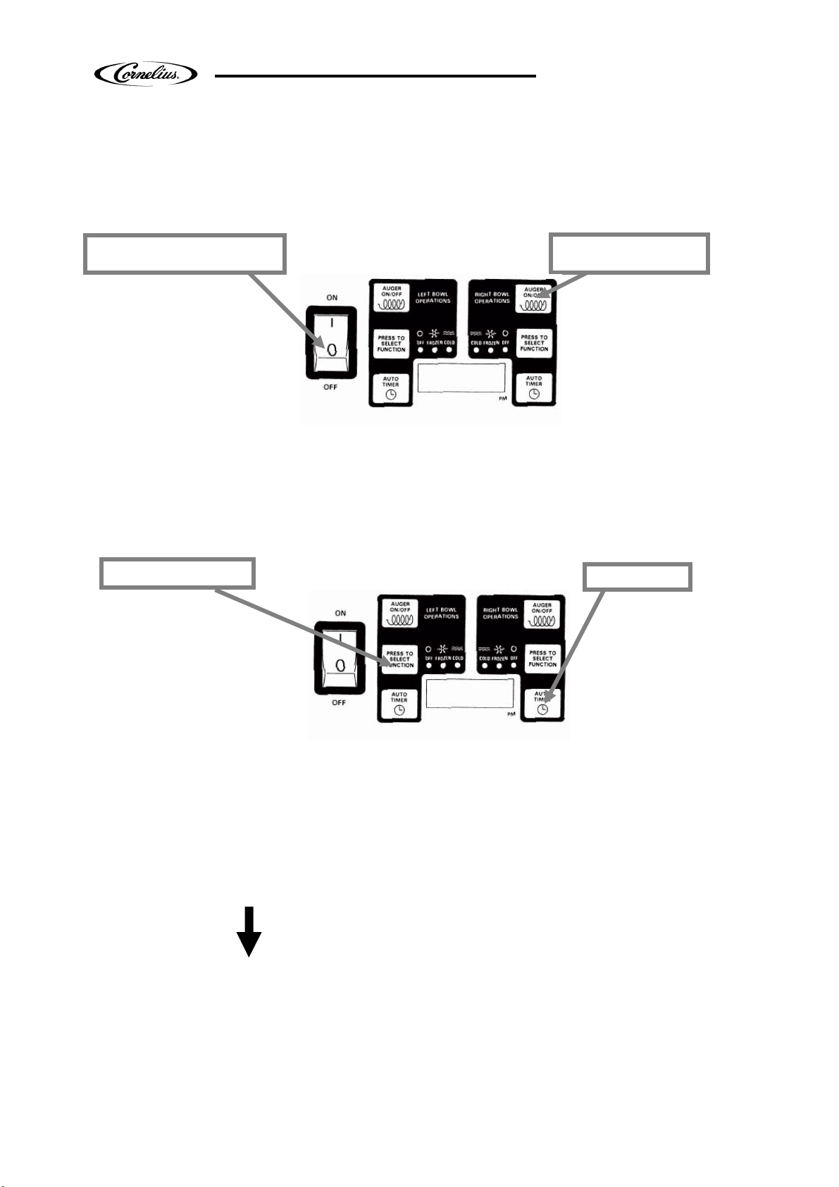
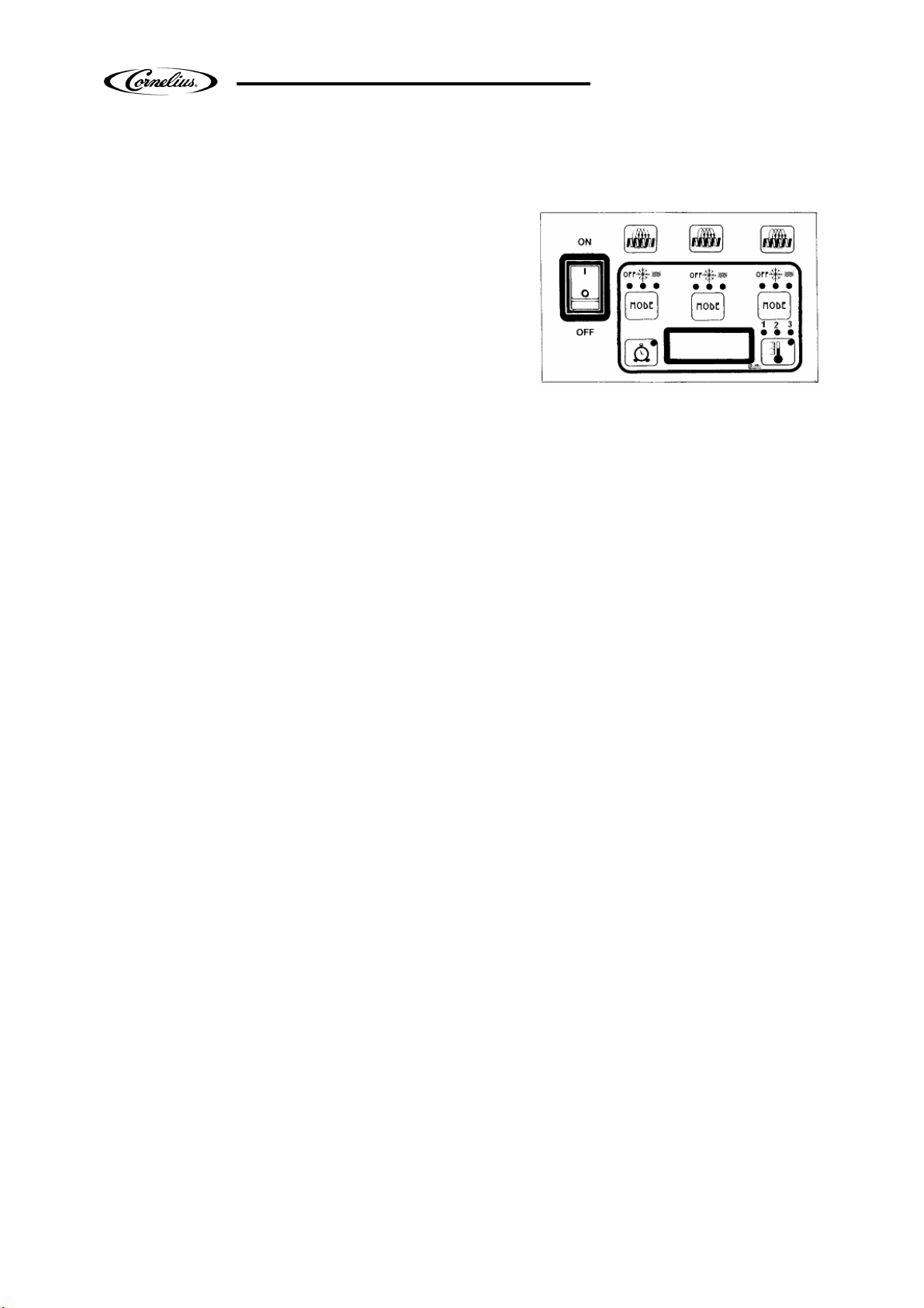
Main Power Switch
Auger ON/OFF
Select Function
Auto Timer
•
PROGRAMMING ELECTRONIC TOUCH PAD
2 bowls 2 compressors
•
Turns unit ON.
•
Selects 12/24 time or
F°/C° temperature display
when turned ON while
simultaneously pressing
the auger button (left one).
•
Sets current time when turned ON
while simultaneously pressing the
“Select function" button.
Fig. 10
•
Must be ON to activate the “Select
function" button to select manual "OFF",
"FREEZE", or "COOLING" functions.
•
Turns auger ON
and OFF when main
power switch is ON.
•
Must be ON to
permit defrost time
to be reset.
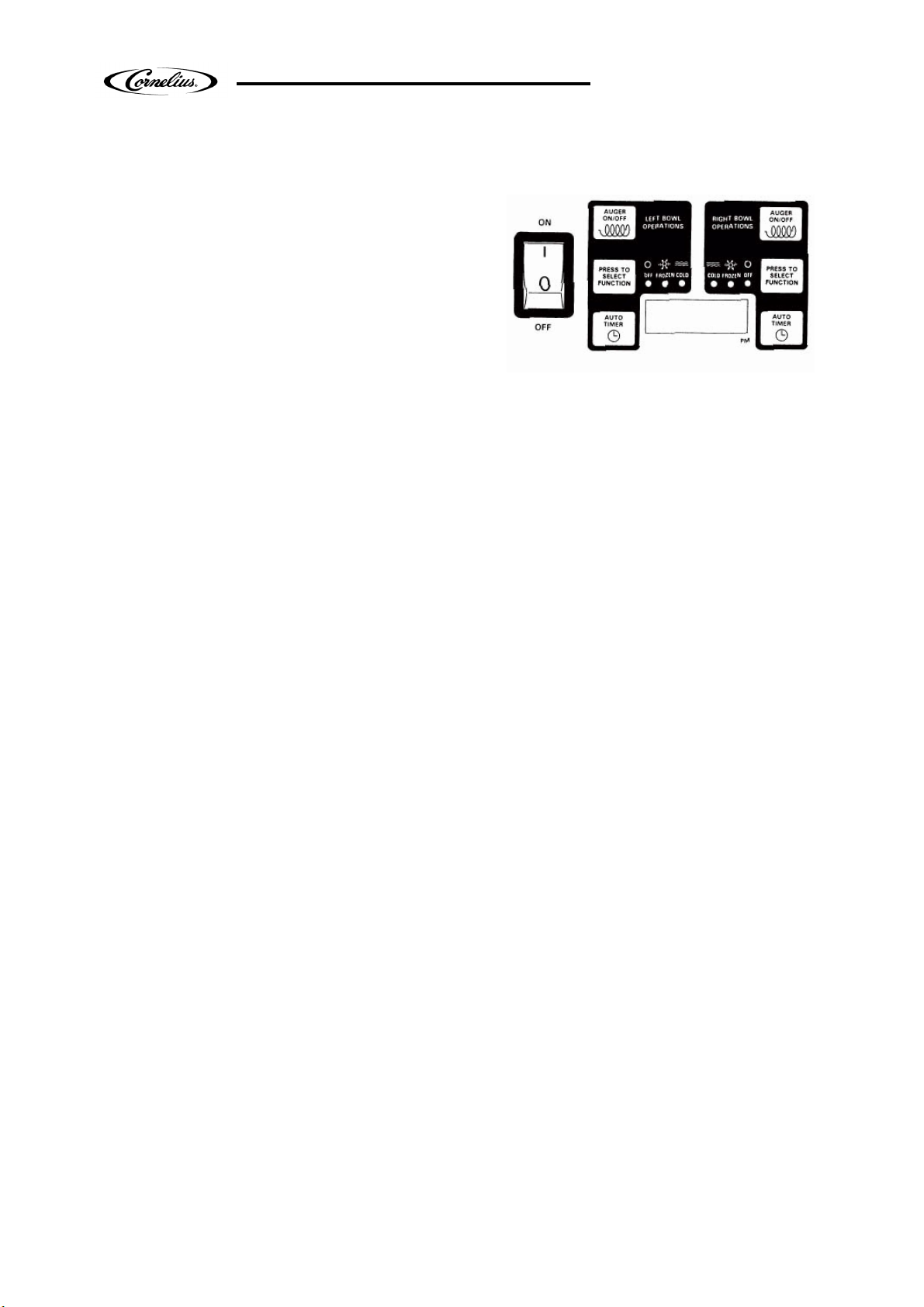
•
•
Used to manually select
"OFF", FREEZE", or
"COOLING" functions when
auger is turned ON.
•
Accesses defrost timer
reset mode when pressed
for an extended period
•
when auger is turned ON.
Does not function when light on "Auto Timer".
•
Locks in hours, minutes and final time
settings after they are reset using the
"Auto Timer" button.
•
Reset:
Press and hold the “Auto timer” button on the left. Turn the main switch ON and wait
until “PreS” appears on the display.
Used to adjust the hours and
minutes settings when
readjusting current time or auto
defrost timer.
Turns auto defrost
mode ON or OFF
(light on switch
indicates when
auto defrost mode
is activated).
Release Date: 20/04/10
Publication Number:
Revision: 8
Pag. : 12/59
Page 13
VFCB Operator’s Manual
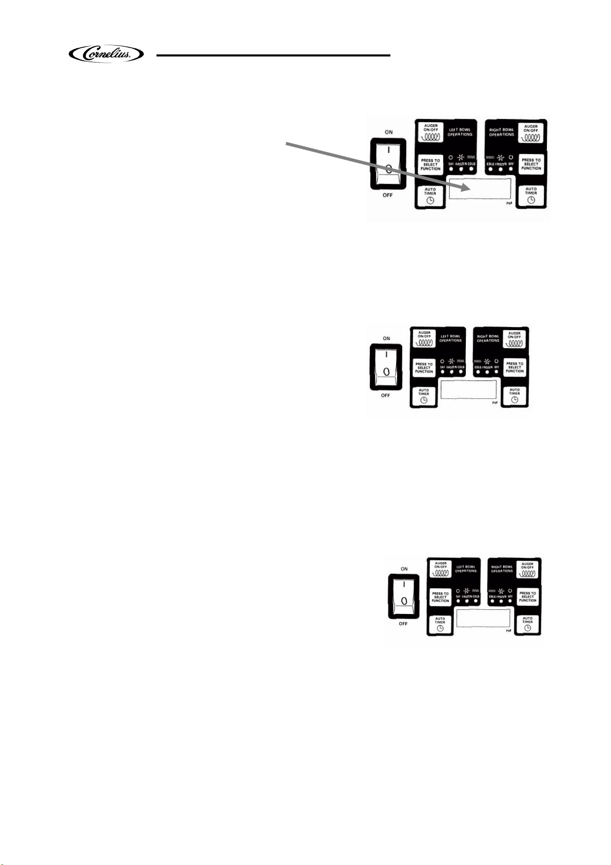
Setting Defrost Timer (Night Setting)
•
t the time you want the machine to turn to freezing mode by following steps above.
NOTE: Once the settings have been saved, the unit will keep the settings
.
Enter Time Programming on Initial Installation or in the Event of a Time Change
hour clock the time is P.M when the dot at the bottom
LEFT BOWL
•
Turn the power switch OFF.
•
Press and hold the left “Select function"
button and turn ON the power switch.
Release the “Select Function" button
when the hour digits start blinking.
•
Set the hour by pressing the "Auto
Timer" clock button until the appropriate
hour is shown.
NOTE: When using a 12
right corner of the LED display is lit; A.M. when dot is not lit.
•
Press the left “Select function" button to set the minutes, then press the "Auto Timer“
clock button until the appropriate minutes are set.
•
Press the “Select function" button one more time to save your settings.
Turn the power switch ON. Make sure the "Auto Timer" is OFF.
•
Press the left "Auger ON/OFF" button ON.
•
Press and hold the “Select function" button until you hear a long beep and the LED,
"Cold" and the "Auto Timer" clock light begins to blink.
•
Press the "Auto Timer" clock button to set the hour you want it to turn to refrigeration
mode, (defrost mode) and then press the “Select function" button to save the hour
setting.
•
Press the "Auto Timer" clock button to set the minutes to complete time setting that
you want it to turn to refrigeration mode (defrost mode). Then press the “Select
function" button to save the minute setting. The "Cold" light will turn off and the
"Freeze" light and "Auto Time" light will begin blinking.
•
Se
Then press the “Select function" button to save the time settings for freeze mode.
NOTE: When the light on the "Auto Timer" clock button is "ON", the defrost timer
is activated. To turn OFF the defrost timer, press the "Auto Timer" clock button
(s) until the light (s) on the clock button (s) turns off.
Release Date: 20/04/10
Publication Number:
Revision: 8
Pag. : 13/59
Page 14
VFCB Operator’s Manual
Setting the 12 or 24 Hour Display
•
Operate in Automatic Mode (with Defrost Timer Activated)
Operate in Manual Mode (without Defrost Timer Activated)
product
•
Turn power switch ON and wait for LED
display to light up.
•
Press the left hand "Auger ON/OFF" button ON.
•
To operate in defrost mode press the "Auto Timer"
button until it is illuminated.
•
When setting automatic times, please keep in mind it will take time for the frozen
product to become liquid or vice versa.
NOTE: As regard the RIGTH BOWL repeat the same operations using the buttons
on the right side of the touch pad.
•
Turn the power switch ON and wait for
LED display to light up.
•
Make sure the clock button is OFF (LED
light on clock button should not be lit up).
•
First turn auger on by pressing the "Auger ON/OFF"
button until it beeps.
NOTE: The auger must be on before the unit will allow the cooling or freezing
mode to be activated.
•
Then select refrigeration or freezing mode by pressing the “Select function"
button until the light under the selection you desire is lit up.
NOTE: In the cooling mode, the LED will read the actual temperature of the
(the temperature setting is preset to NSF standards and is not adjustable). In the
"Freeze" or "Off" mode the LED will read the current time.
•
Turn the power switch OFF.
•
Press and hold the left "Auger On/Off" button and turn
the power switch ON. Release the "Auger On/Off" button
when either "12" or "24" are shown (indicates the current
hour view).
Press the "Auto Timer" button until the desired hour display type is shown (12 to 24).
•
Press the "Select Function" button until the desired temperature display type is
shown (°F or °C).
•
Press the "Select Function" button until the current time is displayed to store the
changes. The unit is now ready for use.
Release Date: 20/04/10
Publication Number:
Revision: 8
Pag. : 14/59
Page 15

VFCB Operator’s Manual
Setting the °F or °C Temperature Display
•
•
Viewing the Bowl Temperature
"Auger On/ Off" button).
•
Turn the power switch OFF.
•
Press and hold the left "Auger On/Off" button and turn ON the power switch. Release the
"Auger On/Off" button when either "12" or "24" are shown (indicates the current hour
view).
Press the "Select Function" button until either °F or °C is shown on the display.
Press the "Auto Timer" button until the desired temperature display type is shown.
•
Store the change by pressing the "Select Function" button until the current time
is displayed. The unit is now ready for use.
•
Press the "Select Function" button until the "Cold" LED is lit. The display will now
show the current bowl temperature in either °F or °C depending on which was
selected in the Setting the °F or °C Temperature Display section.
•
Turn On the auger on the side that you want to display the bowl temperature (press the
“FILTER CLEANING” Alarm
A filter cleaning alarm will activate when the unit is running hot due to insufficient internal air
circulation. When this occurs a “Filt” message will appear on the touch pad LED display readout
and an intermittent audible tone will also sound to alert the operator of this condition.
The “Filt” message will appear when the alarm activates (a beeping sound every 4-5 seconds).
To determine the condition that caused the alarm, see list of conditions below:
• Condition: The filter is dirty and needs to be cleaned.
Corrective Action: Clean and replace filter following instructions(Removing and Cleaning Filter).
• Condition: The unit is positioned too close to a wall or other object restricting air flow and
causing the machine to run at a higher temperature.
Corrective Action: Reposition unit to maximize ventilation space (Installation Instructions).
• Condition: The filter is not properly installed.
Corrective Action: Properly install filter (Removing and cleaning filter).
• Condition: The unit has been installed near a heat source, such as a coffee machine, ice
maker or cold beverage machine which expels hot air from its vents, causing the machine to
run at a high temperature (installation near a heat source should be avoided)
Corrective Action: Reposition unit to maximize ventilation space.
“SYSTEM OVER TEMPERATURE” Alarm
A system over temperature alarm will activate as a safety precaution when the unit has
overheated to protect the compressor.
• The system automatically goes to “OFF” status where the compressor’s operations is
stopped, while augers will keep working to avoid forming ice blocks.
• When this occurs an “Err” message will appear on the touch pad LED readout accompanied
by a continuous buzzer sound to alert the operator of this condition.
• When this alarm activates, turn off all switches. Then determine the condition. (See “Filter
Cleaning” Alarm Section for Conditions and Corrective Actions)
Release Date: 20/04/10
Publication Number:
Revision: 8
Pag. : 15/59
Page 16
VFCB Operator’s Manual
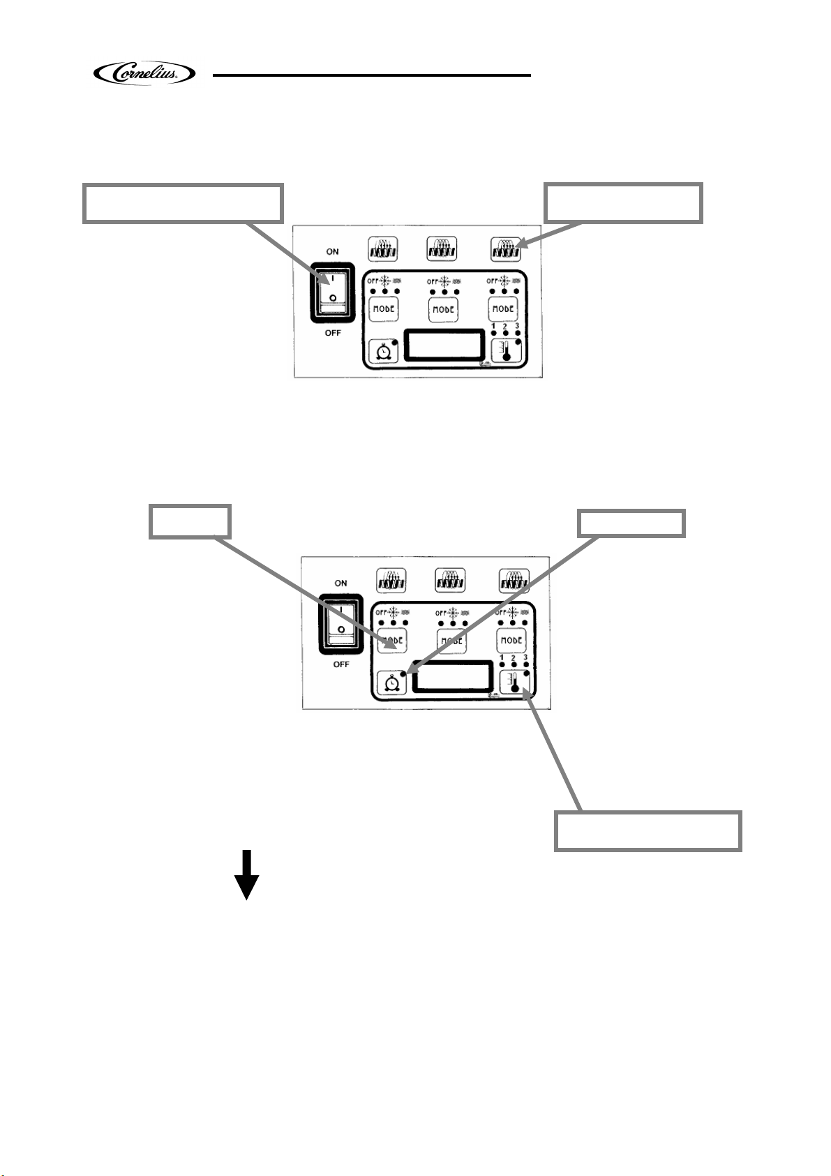
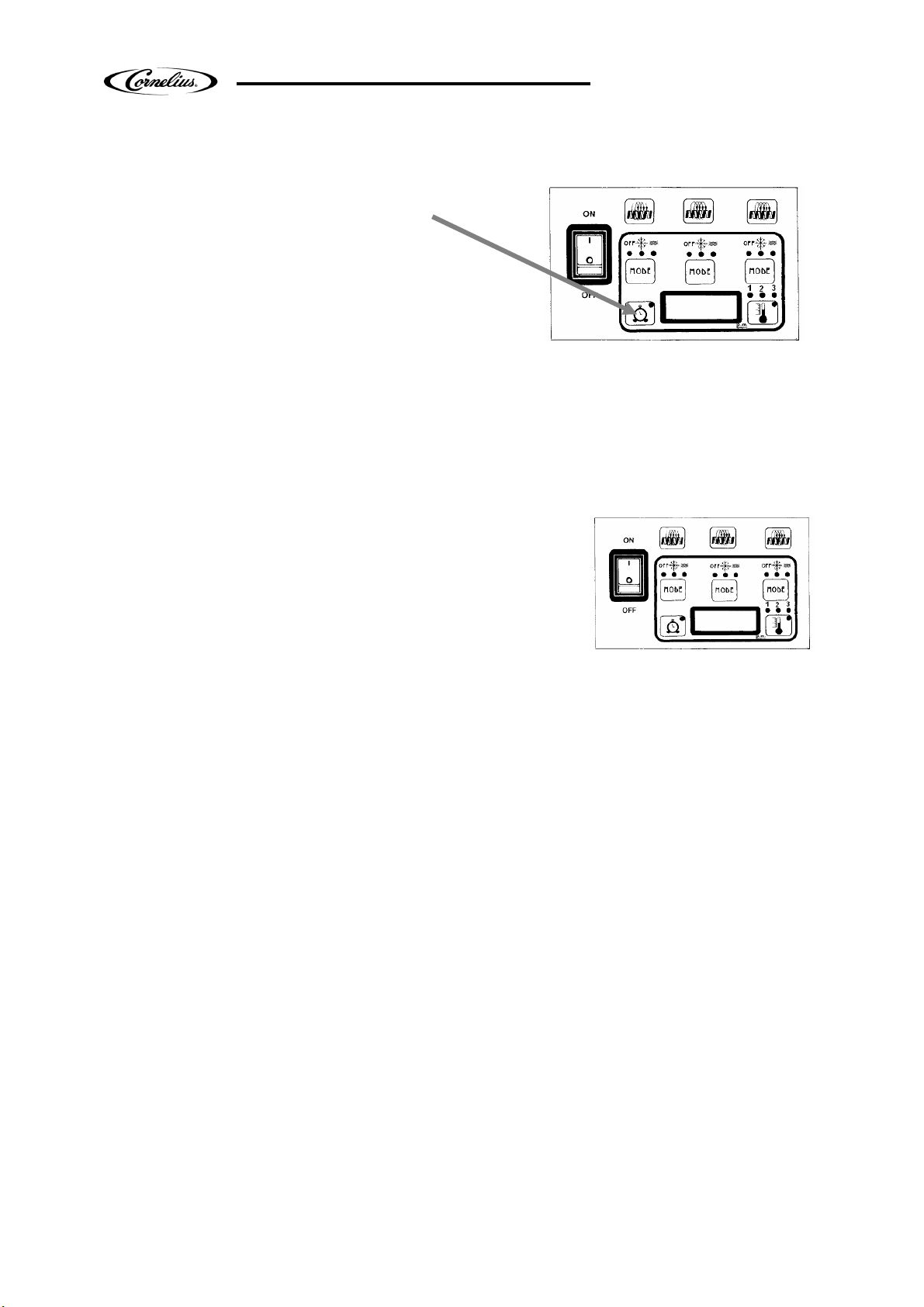
Main Power Switch
Auger ON/OFF
MODE
•
Bowl temperature
product temperature inside the bowl.
3 bowls 3 compressors
•
Turns unit ON.
•
Selects 12/24 time
when turned ON while
simultaneously pressing
the auger button (left one).
•
Sets current time when turned ON
while simultaneously pressing the left
“MODE” button.
•
Turns auger ON
and OFF when main
power switch is ON.
•
Must be ON to
permit defrost time
to be reset.
Fig. 11
•
Must be ON to activate the “MODE”
button to select manual “OFF”,”FREEZE”,
or “COOLING” functions.
Auto Timer
•
•
Used to manually select
“OFF”, “FREEZE”, or
“COOLING” functions when
auger is turned ON .
•
Accesses defrost timer
reset mode when pressed
for an extended period
when auger is turned ON.
Does not function when light on “Auto Timer”.
•
Locks in hours, minutes and final time
settings after they are reset using the
“Auto Timer” button.
•
In defrost condition used to show the
•
Reset:
Press and hold the “Auto timer” button. Turn the main switch ON and wait until “PreS”
appears on the display.
Turns auto defrost
mode ON or OFF
(light on switch
indicates when
auto defrost mode
is activated).
•
Used to adjust the
hours and minutes
settings when
readjusting current
time or auto defrost
timer.
Release Date: 20/04/10
Publication Number:
Revision: 8
Pag. : 16/59
Page 17
VFCB Operator’s Manual
Setting Defrost Timer (Night Setting)
•
NOTE: Once the settings have been saved, the unit will keep the settings
.
Enter Time Programming on Initial Installatio
n or in the Event of a Time Change
NOTE: When using a 12 hour clock the time is P.M when the dot at the bottom
•
Turn the power switch OFF.
•
Press and hold the left “MODE” button and
turn the power switch ON.
Release the “MODE” button when the hour
digits start blinking.
•
Set the hour by pressing the “Auto
Timer” clock button until the appropriate
hour is shown.
right corner of the LED display is lit; A.M. when dot is not lit.
•
Press the left “MODE” button to set the minutes, then press the “Auto Timer” clock
button until the appropriate minutes are set.
•
Press the left “MODE” button one more time to save your settings.
Turn the power switch ON. Make sure the “Auto Timer” is OFF.
•
Press the “Auger ON/OFF” button ON (one at least) .
•
Press and hold the left “MODE” button until you hear a long beep and the LED,
"Cold" and the "Auto Timer" clock light begins to blink.
•
Press the “Auto Timer” clock button to set the hour you want it to turn to refrigeration
mode (defrost mode) and then press the “MODE” button to save the hour setting.
•
Press the “Auto Timer” clock button to set the minutes to complete time setting that
you want it to turn to refrigeration mode (defrost mode). Then press the left “MODE”
button to save the minute setting. The “Cold” light will turn off and the "Freeze" light
and “Auto Time” light will begin blinking.
•
Set the time you want the machine to turn to freezing mode by following steps above.
Then press the left “MODE” button to save the time settings for freeze mode.
NOTE: When the light on the “Auto Timer” clock button is “ON”, the defrost timer
is activated. To turn OFF the defrost timer, press the "Auto Timer" clock button
until the light on the clock button turns off.
Release Date: 20/04/10
Publication Number:
Revision: 8
Pag. : 17/59
Page 18
VFCB Operator’s Manual
Operate in Automatic Mode (with Defrost Timer Activated)
Operate in Manual Mode (without Defrost Timer Activated)
and is not adjustable).
•
Turn power switch ON and wait for LED
display to light up.
•
Press "Auger ON/OFF" buttons ON.
•
To operate in defrost mode press the “Auto Timer”
button until it is illuminated.
•
When setting automatic times, please keep in mind it will take time for the frozen
product to become liquid or vice versa.
NOTE: The defrost timer is the same for all the bowls.
The defrost mode can be activated only if one auger button at least is on.
•
Turn the power switch ON and wait for
LED display to light up.
•
Make sure the clock button is OFF (LED
light on clock button should not be lit up).
•
First turn auger on by pressing the “Auger ON/OFF”
button until it beeps.
NOTE: The auger must be on before the unit will allow the cooling or freezing
mode to be activated.
•
Then select refrigeration or freezing mode by pressing the “MODE” button until the light
under the selection you desire is lit up.
NOTE: In the cooling mode, the LED display will read the actual temperature of the
product (the temperature setting is preset to NSF standards
Pushing the thermometer button it is possible to see the temperature into the left
bowl (led 1 light up) or into the right one (led 2 light up).
In the “Freeze” or “Off” mode the LED will read the current time.
Release Date: 20/04/10
Publication Number:
Revision: 8
Pag. : 18/59
Page 19

Setting the 12 or 24 Hour Display
•
Viewing the Bowl Temperature
VFCB Operator’s Manual
•
Turn the power switch OFF.
•
Press and hold the left "Auger On/Off" button and
turn the power switch ON. Release the "Auger On/Off"
button when either “12” or “24” are shown (indicates
the current hour view).
Press the “Auto Timer” button until the desired hour display type is shown (12 to 24).
•
Press the left “MODE” button on the left until the desired temperature display type is
shown (°F or °C).
•
Press the left “MODE” button on the left until the current time is displayed to store the
changes. The unit is now ready for use.
•
Press the left “MODE” button until the “Cold” LED is lit, than press the “bowl
Temperature “ button choosing the bowl. The display will now show the current bowl
temperature in either °F or °C depending on which was selected in the Setting the
°F or °C Temperature Display section. Turn On the auger on the side that you want
to display the bowl temperature (press the “Auger On/ Off” button).
“FILTER CLEANING” Alarm
A filter cleaning alarm will activate when the unit is running hot due to insufficient internal air
circulation. When this occurs a “Filt” message will appear on the touch pad LED display readout
and an intermittent audible tone will also sound to alert the operator of this condition.
The “Filt” message will appear when the alarm activates (a beeping sound every 4-5 seconds).
To determine the condition that caused the alarm, see list of conditions below:
• Condition: The filter is dirty and needs to be cleaned.
Corrective Action: Clean and replace filter following instructions(Removing and Cleaning Filter).
• Condition: The unit is positioned too close to a wall or other object restricting air flow and
causing the machine to run at a higher temperature.
Corrective Action: Reposition unit to maximize ventilation space (Installation Instructions).
• Condition: The filter is not properly installed.
Corrective Action: Properly install filter (Removing and cleaning filter).
• Condition: The unit has been installed near a heat source, such as a coffee machine, ice
maker or cold beverage machine which expels hot air from its vents, causing the
machine to run at a high temperature (installation near a heat source should be
avoided)
Corrective Action: Reposition unit to maximize ventilation space.
“SYSTEM OVER TEMPERATURE” Alarm
A system over temperature alarm will activate as a safety precaution when the unit has
overheated to protect the compressor.
• The system automatically goes to “OFF” status where the compressor’s operations is
stopped, while augers will keep working to avoid forming ice blocks.
• When this occurs an “Err” message will appear on the touch pad LED readout accompanied
by a continuous buzzer sound to alert the operator of this condition.
• When this alarm activates, turn off all switches. Then determine the condition. (See “Filter
Cleaning” Alarm Section for Conditions and Corrective Actions)
Release Date: 20/04/10
Publication Number:
Revision: 8
Pag. : 19/59
Page 20

VFCB Operator’s Manual
CONSISTENCY ADJUSTMENT
1. To dispense the product, place the cup
beneath the tap (Q) and lower the lever (R)
very gently (Fig.12).
2. Adjusting the consistency:
To vary the consistency of the ice slush, turn
the knob (S) as shown in Fig. 13. Turning the
knob counter-clockwise will increase viscosity
(make the product denser). Turning the knob
clockwise will decrease viscosity (make the
product less dense).
ATTENTION: This device only changes the
consistency of the ice slush
dispensed, it does not effect the
cooling temperature.
ATTENTION: When the level of the ice slush
inside the bowl is below the
minimum, to stop the product
becoming too dense you must
switch off the cooling system
(OFF position), or top up the
bowl,
An indicator gauge for reference is located on the
back of the unit approximately 6 inches below the
adjustment knob.
Fig. 12
Fig. 13
Release Date: 20/04/10
Publication Number:
Revision: 8
Pag. : 20/59
Page 21

VFCB Operator’s Manual
SIX MONTHLY CLEANING AND SANITATION
OPERATIONS:
ATTENTION: The cleaning operations must be
performed with the machine
disconnected from the power supply.
1. Empty the bowl of any remaining product and switch
off the main switch.
2. Remove the cover (B) – Fig. 14.
3. Extract the quick couplings (C2) / (F2) - (Fig.
15, 16, and 17).
4. Disconnect the probe fastenings (D2) / (E2) - (Fig. 15 and 16).
Fig. 14
Fig. 15
Release Date: 20/04/10
Publication Number:
Revision: 8
Pag. : 21/59
Fig. 17
Fig. 16
Page 22

VFCB Operator’s Manual
5. Pull the lock pin/safety pin (Y) upwards, if the machine version is
without pin, unscrew one of the two locking knobs (Y1) – Fig.18.
Y1
Fig. 18
6. Slide the locking bar (Z) – Fig. 19 - outwards so that the bowls are
fully released. Unlock relief valve on the bowl lid cap and remove it
(Fig. 20).
Fig. 19
7. Lift the bowl lid cap lever (Fig. 20), remove the cap, unscrew the
knobs (A1) so the bowls can be lowered slightly, open the tap to
remove any remaining liquids and then extract the bowl from its
seating, pulling it outwards (Fig. 20).
Fig. 20
8. Remove the tap from its seating, pressing the two clamping wings at
the same time (Fig. 21) and pushing upwards.
Fig. 21
9. Dismount the tap, holding the body (R) pressed downwards, then
slide the lever (L) out of its seating (Fig. 22). Wash all the parts
thoroughly with hot water and washing-up liquid, rinse them well, and
proceed to remount them.
10. Separate the bowl from its cover, releasing the fastening (D1)
by pulling them upwards as shown in Fig.23.
Release Date: 20/04/10
Publication Number:
Revision: 8
Pag. : 22/59
Fig. 22
Fig. 23
Page 23

VFCB Operator’s Manual
11. Wash the bowl lid cap (Fig. 20), the bowl and its cover
carefully with water and washing-up liquid, rinse them well, and
proceed to remount them, making sure the sealing strip (E1) is
positioned correctly between the cover and the bowl. To
guarantee the seal, the rounded part of the said sealing strip (as
shown in Fig. 24) must be facing the cover.
12. Unscrew the fastening knob (F1) clockwise as the
direction indicated by the arrow (threading to the left) and
proceed by extracting the spiral scraper (G1) and the seals (H1)
and (I1). Clean the individual parts thoroughly (Fig. 25).
13. Clean the drip tray (J1) and the evaporator (K1) well (Fig. 26).
CAUTION: Do not wash any components in a dishwasher.
14. Proceed to remount the mixing unit as follows:
• dampen the sealing strip (l1) and insert it into its seating in
the correct position (Fig. 26A);
• apply a copious amount of Vaseline (supplied with the
machine) to the suction cup seal (H1) (on the part that comes
into contact with the evaporator K1) and insert it in its spiral
seating (Fig. 25 , Fig. 26);
• remount the spiral scraper (G1) (Fig.25);
• fasten all the components in place by screwing the knob F1
counter-clockwise (Fig.25).
15. Remount the bowl by pushing it into its seating (Fig. 27).
16. Proceed to fasten the bowl in place by tightening the
knobs (A1) – Fig. 26 and the locking bar (Z) – Fig. 19.
Fig. 24
Fig. 25
Fig. 26
Fig. 26A
Fig. 27
17. Remount the tap, remembering to smear both is seating in the bowl
and the seals (J) with Vaseline (Figure 28).
Release Date: 20/04/10
Publication Number:
Revision: 8
Pag. : 23/59
Fig. 28
Page 24

VFCB Operator’s Manual
18. Dismount the drip tray (L1) by rotating it slightly and pulling
it outwards (Fig. 29). Wash all the parts carefully and
proceed to reassemble it by following the aforesaid
operations, remembering to reinsert the condensation
discharge pipe (M1) in its seating.
Fig. 29
19.If the drip tray is outfitted with coupling T0(Fig. 30) it is
possible to discharge the water in the drip tray without
removing it. In order to do that proceed as follow:
• remove the tap T1 (Fig. 30);
• connect a tube with the coupling T0 (Fig. 30).
NOTE:
“Six monthly” cleaning procedure is the standard time and it is suitable for the most of the
products, but the cleaning procedure depends on the kind of product used. If the product used
is a made of milk or 100% fruit plus sugar, for example, “Three monthly” cleaning procedure is
request. In case of doubt please contact the assistance or do the “Three monthly” cleaning
procedure.
Fig. 30
Release Date: 20/04/10
Publication Number:
Revision: 8
Pag. : 24/59
Page 25

VFCB Operator’s Manual
SPECIAL MAINTENANCE
MANIFOLD AND BACK RELIEF VALVES CLEANING
ATTENTION: To guarantee the good functioning of the safety system, the cleaning of
the manifold and of the back relief valve is essential.
It’s essential to perform the manifold draining procedures
once a month proceeding as follows:
• disconnect the machine from the power supply;
• dismount the cover (B) – Fig.32;
• disconnect the plug (D) – Fig.33;
• un-thread the back (E) – Fig.33, pulling it high.
• extract the draining tube (R) by unrolling it – Fig.30A;
• drain the product inside a manifold opening the tap (S) -
Fig.30A.
• close the tap ed restore the tube in the initial position.
It’s essential to perform the back relief valves cleaning procedures every three months
proceeding as follows:
• disconnect the machine from the power supply;
• dismount the cover (B) – Fig.32;
• disconnect the plug (D) – Fig.33;
• un-thread the back (E) – Fig.33, pulling it high.
• disconnect the fast-on connections from the
valve;
• disassemble the relief valve coil Z by
unscrewing its fixing nut N with a N°15 monkey
spanner– Fig.30B;
• disassemble the relief valve body V by
unscrewing it with a N°18 monkey spanner–
Fig.30B;
• once disassembled, carefully wash the body V,
the conical spring T and the piston U in order to
clean them from product residuals - Fig.30B.
• carefully dry up all the disassembled parts;
• reassemble the spring on the piston in the right direction as described in picture 30B;
• reassemble all other parts carefully tightening them in order to avoid air leakage during the
functioning.
You are reminded that all the operations described above must be carried out with
the machine switched off and the power cable disconnected.
Fig. 30A
Fig. 30B
Release Date: 20/04/10
Publication Number:
Revision: 8
Pag. : 25/59
Page 26

VFCB Operator’s Manual
CONDENSER FILTER CLEANING
ATTENTION: To guarantee the cooling system a good performance level, the routine
cleaning of the condenser filter is essential.
As explained earlier, an acoustic signal, accompanied by the word
FILT appearing on the control panel display, will warn the operator
when the filter is clogged and so must be cleaned before the
machine comes to an automatic stop.
Proceed as follows:
• disconnect the machine from the power supply;
• remove the filter as showed in Fig. 31 and clean it;
• dismount the cover (B) – Fig. 32;
• disconnect the plug (D) – Fig. 33;
• un-thread the back (E) – Fig. 33, pulling it high.
• clean the condenser with a brush if necessary (Fig.34).
You are reminded that all the operations described above
must be carried out with the machine switched off and the
power cable disconnected.
INSUFFICIENT AIR FLOW ALARM
To protect the entire cooling system, the ice slush drinks
maker is fitted with an electronic system which issues an
acoustic warning signal in the event of insufficient
ventilation or if the condenser filter is clogged with dust. In
addition to this, the words Filt and then Err will appear on the
control panel display.
If the operator does not intervene when the signal is issued,
restoring normal working conditions (i.e. ensuring better
ventilation or cleaning the filter), this electronic system will stop
the machine automatically.
Fig. 31
Fig. 32
Fig. 33
Fig. 34
Release Date: 20/04/10
Publication Number:
Revision: 8
Pag. : 26/59
Page 27

VFCB Operator’s Manual
SEAL MAINTENANCE
SPINDLE BUSHING: replace every 6 to 12 months
depending on conditions of use and level of maintenance.
Replacement should ONLY be done by a qualified service
technician
• Remove the Rulon bushing using a flathead screwdriver as
shown
• Insert the brass guide tool on the drive shaft and slip the
bushing over the guide tool and firmly press into place.
• Using the special tool C and rubber mallet, gently seat the
bushing into place as shown
• Lubricate the bell shaped seal and reassemble onto
evaporator/auger shaft.
BELL SHAPED SEAL: replace every 1 to 6 months depending on conditions of use,
level of maintenance and lubrication. This part should be lubricated during
reassembly after every cleaning
BOWL GASKET: it’s the red gasket located at the rear of the bowl, replace as
necessary depending on conditions of use and level of maintenance; this part should
be lubricated during the re-assembling after every cleaning.
O-RING: the dispense valve o-ring should be replaced every 6 to 12 months or as
necessary when wear is apparent. Lubricate the o-ring each time they are replaced
or the dispense handle is removed for cleaning
Release Date: 20/04/10
Publication Number:
Revision: 8
Pag. : 27/59
Page 28

VFCB Operator’s Manual
ELECTRONIC MONITORING
ELECTRONIC MONITORING AND SAFETY
SYSTEM
GENERAL FEATURES
The diagram shows the electronic pressures and
levels management system:
1. Safety valve
2. Cut out level bowls control board
3. Bowl 1 discharge solenoid valve
4. Bowl 2 discharge solenoid valve
5. CO2 inlet solenoid valve
6. Pressure and levels control board
7. Draining tube
8. Tube to the bowl 1
9.Tube to the pressure and level control board (6)
10.Tube to the operating pressure gauge
11.Tube to the bowl 2
Fig. 35
The diagram shows the pressures and levels management system in the 3 bowls VFCB:
1. Safety valve
2. Cut out level bowls control board
3. Bowl 1 discharge solenoid valve
4. Bowl 2 discharge solenoid valve
5. CO2 inlet solenoid valve
6. Pressure ( bowls 1,2 and 3) and levels
(2 and 3) control board
7. Draining tube
8. Tube to the bowl 1
9.Tube to the pressure and level control
board (6)
10.Tube to the operating pressure gauge
11.Tube to the bowl 2
12. Level control board (bowl 1)
13. Bowl 3 discharge solenoid valve
14. Bowl 3 discharge solenoid valve
Fig. 36
Release Date: 20/04/10
Publication Number:
Revision: 8
Pag. : 28/59
Page 29

VFCB Operator’s Manual
switch
Left Bowl
Right Bowl
VFCB POST MIX
Safety Probes
Level Probes
Sold Out
pressure
Description
Sold out = Pressure switch / product presence
The “sold out” pressure switches ,set on the electro-valves, detect the presence (or not) of
product in the bag in box. The “sold out” pressure switches are not related to ANY control
board. They work INDEPENDENTLY one from the other (left bowl sold out works
independently from right bowl sold out). When the “sold out” pressure switches detect the lack
of product, they stop the mix (product and water) dispensing. In managing bowls level
condition they are active only during a bowl loading phase
Level bowl =Level probes
The “level bowl” probes function is to control and manage the product level in the bowl. They
work INDEPENDENTLY one from the other (left bowl level probes work independently from
right bowl level probes).
Cut out level bowl = overflow probes
The “cut out level bowl” probes are safety probes. Their function is to avoid bowl’s overflow if
the “level bowl” probes are out of function (both of them or just one of them). If they are
active they inhibit the “pressure and level control board”.
Release Date: 20/04/10
Publication Number:
Revision: 8
Pag. : 29/59
Page 30

VFCB Operator’s Manual
If the “level bowl” probes are uncovered ,the mix is introduced in the bowl. If the “sold out”
During the first filling condition it necessary that both “level bowl” probes (the left bowl and
“Sold out” Pressure switch
Active
only
during the
bowl loading phase
“Sold out” Pressure switch
Pressure means product, no pressure means no product
First Filling Condition
First Filling Condition
Each time the unit is turned off and then turned on
Each time the there is a lack of power supply to the unit
First Filling Condition
pressure switch has detected product ,the bowl filling goes on until the “level bowl” probes
are covered (4 minutes max); otherwise the unit begins to buzz after 4 minutes because
the “level bowl” probes are not covered yet and the led (out of product) on the frontal
panel is lit. So that it is necessary to turn the unit off, remove the empty bag in box,
replace it with a new one and turn the unit on. The unit will work as a first filling condition.
the right one) are reached otherwise the unit begins to buzz and it does not work
“Sold out” pressure switch begins to work only if it detects product
4 minutes is the maximum time for filling the bowls
Managing bowl Level
“Level bowl” probes
uncovered
Product introduced in the bowl until the “level bowl”
probes are covered
The “pressure and level control board” INDIRECTLY detects the lack of product because
when the “sold out” pressure switch , set on the electro-valve, has detected the product
missing, it stops the mix dispensing. In this situation the “level bowl” probes will never
be covered, so after 1 minute (set time) the “pressure and level control board” detects
the lack of product and the led (out of product) on the frontal panel is lit.
If the “level bowl” probes are not covered by a minute ( i.e. the unit dispenses the mix
continuously so the mix introduced in the bowl does not counterbalance the mix
dispensed) the bowl loading phase stops and it is necessary to turn the unit off and then
turn the unit on. The unit works as a first filling condition.
Release Date: 20/04/10
Publication Number:
Revision: 8
Pag. : 30/59
Page 31

VFCB Operator’s Manual
it will work as a first filling condition.
the bowl loading phase
the product level in the
Overflow Condition
The overflow condition
only if the “level
bowl” probes are out
of service (both of
them or just one)
The overflow condition
If just one “cut out
level bowl” is reached
it is enough to stop
in both the bowls.
When the product
level in the bowl
reaches the “cut
out level bowl”
probes the unit
interrupts the bowl
loading phase.
Until both “cut out
level bowl” probes are
uncovered the product
can not be introduced
in any bowl ( i.e. until
left bowl is not under
the LT “cut out level
bowl” ,the unit do not
fill the right bowl).
Case Study
Some events that can happen during unit working are following:
1. If a bag in box is empty during the first filling condition, the “sold out” pressure switch,
set on the electro-valve, detects the lack of product and stops mix dispensing. After 4
minutes the “pressure and level control board” turns the frontal led (out of product)
on. So that it is necessary to turn the unit off, remove the empty bag in box , replace it
with a new one and turn the unit on. The un
2. If the unit is switched off and then switched on without removing the empty bag in
box, the unit works as a first filling condition and it happens the same situation
described at point 1.
3. If the “level bowl” probes are covered and the unit is switched off and then switched on,
the unit ignores the first filling condition because the “level bowl” probes are already
covered.
4. If the product inside a bag in box finishes during a managing bowl level, it is necessary
to switch the unit off, remove the empty bag in box and replace it with a new one and
then turn the unit on. The unit works as a first filling condition and, when the “level
bowl” probes are covered, the unit stops the mix dispensing in the bowl.
5. If the product inside a bag in box finishes as soon as the “level bowl” probes are
covered, the unit does not detect the end of product. As soon as the “level bowl” probes
are uncovered the “sold out” pressure switch detects the end of product and stops the
mix dispensing. After 1 minute the “pressure and level control board” lights the relative
led (out of product) on. So that it is necessary to turn the unit off, remove the empty
bag in box , replace it with a new one and turn the unit on. The unit will work as a first
filling condition.
Release Date: 20/04/10
Publication Number:
Revision: 8
Pag. : 31/59
Page 32

VFCB Operator’s Manual
Presence Probes
Electrovalve
Bowl Pressure Managing
The pressure inside the bowls is managed by the “pressure and level control board”.
First filling condition
In first filling condition the pressure inside the bowls is not checked until product reaches the
“level bowl” probes in BOTH the bowls. When the “level bowl” probes are satisfied in BOTH the
bowls the “pressure and level control board” begins to work and maintains the pressure inside
each bowl between 120mbar (on ) e 160mbar (off). After 1 minute and 30 seconds, if the
pressure inside the bowls does not reach 160mbar, there are 2 possibilities:
• there is no more gas in the CO2 external tank; so the “out gas” frontal led is lit and it is
necessary to turn the unit off, remove the empty CO2 tank and replace it with a new
one
• there is a lack of CO2; so the CO2 dispensing is interrupted in order to avoid the CO2
external tank run out. It is important to find out the origin of this lack.
Pressure managing
The pressure inside the bowl (between 120mbar e 160mbar) is managed INDEPENDENTLY
from “level bowl” probes. For example if the “level bowl” probes (in both bowls or just in one)
are uncovered and a bag in box is empty, the led (out of product) on the frontal panel is lit
(after 1 minute) but the pressure inside the bowl remains between 120mbar e 160mbar even if
the bag in box is not removed and replaced with a new one.
VFCB PRE MIX
Safety Probes
Level Probes
Product
Left Bowl Right Bowl
Description
Sold out = Product presence probes
The “sold out” probes detect the presence (or not) of product in the external tank/s.
They work independently one from the other (left bowl sold out works independently from
right bowl sold out). In first filling condition they are working after 30 seconds from the unit
switched on . In managing bowls level condition they are active only during a bowl loading
phase and they are working with an hysteresis of 3 seconds.
Level bowl =Level probes
The “level bowl” probes function is to control and manage the product level in the bowl. They
work independently one from the other (left bowl level probes work independently from right
bowl level probes).
Cut out level bowl = overflow probes
The “cut out level bowl” probes are safety probes. Their function is to avoid bowl’s overflow if
the “level bowl” probes are out of function (both of them or just one of them). If they are
active they inhibit the “pressure and level control board”.
Release Date: 20/04/10
Publication Number:
Revision: 8
Pag. : 32/59
Page 33

VFCB Operator’s Manual
First Filling Condition
First Filling Condition
First Filling Condition
If the “level bowl” probes are uncovered, the product is introduced in the bowl. After
30 seconds if the “sold out” probes have detected product ,the bowl filling goes on
until the “level bowl” probes are covered (4 minutes max); otherwise the unit begins
to buzz because the external tank is empty (or both tanks or just one as showed by
the led on the frontal panel). So that it is necessary to turn the unit off, remove the
empty tank (or the empty tanks) , replace it (them) with a new one/s and turn the
unit on. The unit work as a first filling condition. During the first filling condition it
necessary that both “level bowl” probes (the left bowl and the right one) are reached
otherwise the unit begins to buzz and it does not work.
Each time the unit is turned off and then turned on
Each time the there is a lack of power supply to the unit
“Sold out” probes begin to work with delay of 30 seconds
from the unit switched on
4 minutes is the maximum time for filling the bowls
Managing bowl Level
“Sold out” probes
Active only during the bowl loading phase
“Sold out” probes
“Level bowl”
probes uncovered
The “sold out” probes detect the product presence (or not) in the external tanks with an
hysteresis of 3 seconds. 3 seconds software hysteresis are introduced to prevent the
probes recognize the tank bowl conduit as empty when there is residual gas in it.
If the “level bowl” probes are not covered by a minute ( i.e. the unit dispenses the mix
continuously so the mix introduced in the bowl does not counterbalance the mix dispensed)
the bowl loading phase stops and it is necessary to turn the unit off and then turn the unit
on. The unit works as a first filling condition.
Release Date: 20/04/10
Publication Number:
Revision: 8
Pag. : 33/59
Detect the lack of product with an hysteresis of 3 second.
Product introduced in the bowl until “level bowl” probes are covered
Page 34

VFCB Operator’s Manual
The overflow condition
pha
se.
Overflow Condition
When the product
level in the bowl
reaches the “cut out
level bowl” probes
only if the “level
bowl” probes are out
of service (both of
them or just one)
The overflow condition
If just one “cut out
level bowl” is reached
it is enough to stop the
bowl loading phase in
both the bowls.
the unit interrupts
the bowl loading
Until both “cut out
level bowl” probes
are uncovered the
product can not be
introduced in any
bowl ( i.e. until the
product level in the
left bowl is not under
the LT “cut out level
bowl” the unit do not
fill the right bowl).
Case Study
It follows some events that can happen during unit working:
1. If external tank (or tanks) is (are) empty during the first filling condition, the “sold
out” probes , after 30 seconds , detect the lack of product and stop the unit. So it is
necessary to switch the unit off, remove the empty tank and replace it with a new
one and then turn the unit on.
2. If the unit is switched off and then switched on without removing the external tank
empty (or tanks), the unit works as a first filling condition and it happens the same
situation described at point 1.
3. If the “level bowl” probes are covered and the unit is switched off and then switched
on, the unit ignores the first filling condition because the “level bowl” probes are
already covered.
4. If the product inside the external tank finishes during a managing bowl level (the
relative led must be lit), it is necessary to switch the unit off, remove the empty
tank and replace it with a new one and then turn the unit on. The unit works as a
first filling condition and, when the “level bowl” probes are covered, the unit stops
the product dispensing in the bowl.
5. If product inside the external tank finishes as soon as the “level bowl” probes are
covered, the unit does not detect the end of product because the monitoring of the
“sold out” probes (covered / uncovered) is active only during the bowl loading
phase. As soon as the “level bowl” probes are uncovered the “sold out” probes
(after 3 second hysteresis ) detect the end of product; so it is necessary to turn the
unit off, remove the empty tank and replace it with a new one and then turn the
unit on.
Release Date: 20/04/10
Publication Number:
Revision: 8
Pag. : 34/59
Page 35

VFCB Operator’s Manual
Bowl Pressure Managing
The pressure inside the bowls is managed by the “pressure and level control board”
First filling condition
In first filling condition the pressure inside the bowls is not checked until product reaches the
“level bowl” probes in BOTH the bowls. When the “level bowl” probes are satisfied in BOTH
the bowls the “pressure and level control board” begins to work and maintains the pressure
inside each bowl between 120mbar (on ) e 160mbar (off). After 1 minute and 30 seconds, if
the pressure inside the bowls does not reach 160mbar, there are 2 possibilities:
• there is no more gas in the CO2 external tank; so the “out gas” frontal led is lit and it is
necessary to turn the unit off, remove the empty CO2 tank and replace it with a new
one
• there is a lack of CO2; so the CO2 dispensing is interrupted in order to avoid the CO2
external tank run out. It is important to find out the origin of this lack.
Pressure managing
The pressure inside the bowl (between 120mbar e 160mbar) is managed INDEPENDENTLY
from “level bowl” probes. For example if the “level bowl” probes (in both bowls or just in one)
are uncovered and the external tank (product tank) is empty, the led is lit in the frontal panel
(after 3 second hysteresis) but the pressure inside the bowl remains between 120mbar e
160mbar even if the external tank is not removed and replaced with new one (product tank).
Release Date: 20/04/10
Publication Number:
Revision: 8
Pag. : 35/59
Page 36

VFCB Operator’s Manual
WIRING DIAGRAM
Release Date: 20/04/10
Publication Number:
Revision: 8
Pag. : 36/59
Page 37

VFCB Operator’s Manual
Release Date: 20/04/10
Publication Number:
Revision: 8
Pag. : 37/59
Page 38

VFCB Operator’s Manual
Release Date: 20/04/10
Publication Number:
Revision: 8
Pag. : 38/59
Page 39

VFCB Operator’s Manual
Release Date: 20/04/10
Publication Number:
Revision: 8
Pag. : 39/59
Page 40

VFCB Operator’s Manual
Release Date: 20/04/10
Publication Number:
Revision: 8
Pag. : 40/59
Page 41

VFCB Operator’s Manual
TROUBLESHOOTING
NOTE: The following procedures must be performed by a qualified service technician.
Problem Possible Cause Solution
“Filt” or “Err” message
appears on the touchpad LED
readout
The machine does not cool, or
cools only partially, but the
compressor/s is/are running
• The filter is dirty and needs
to be cleaned
• The unit is positioned too
close to a wall or other object
restricting air flow and
causing the machine to run at
a higher temperature
• The filter is not properly
installed
• The unit has been installed
near a heat source, such as a
coffee machine, ice maker or
cold beverage machine which
expels hot air from its vents,
causing the machine to run at
a high temperature.
(Installation near a heat
source should be avoid)
• The space around the
machine is inadequate for
ventilation
• Freezer is in defrost
• The condenser fins are
clogged with airborne
particles
• Fan motor is not running
• Refrigerant is leaking
• Clean and replace filter
following instructions
(Removing and Cleaning
Filter)
• Reposition unit to maximize
ventilation space (see
installation figures)
• Properly install filter see
“Removing and cleaning filter”
• Reposition unit to maximize
ventilation space (see
installation figures)
• Allow at least 8” (20cm)
between the machine and
anything next to it; keep
away from heat sources
• Return to freeze mode
• Remove the side panels.
Using a brush or compressed
air clean the condenser
• Check the fan motor’s
electrical connections and, if
disconnected, reconnect. If
still not operating, replace the
motor
• Locate the leak, eliminate it
and recharge the system
Release Date: 20/04/10
Publication Number:
Revision: 8
Pag. : 41/59
Page 42

VFCB Operator’s Manual
The machine over-freezes,
making the auger movement
slow or stopped
The machine is noisy
The main power switch is
“On”. The unit is not running.
• Electrical components of the
compressor(s) are not
functioning
• Some electrical connections
are not complete
• One or more of the
compressors are
malfunctioning
• No current is coming to the
“compressor delay” mother
board
• The product brix is too low
• The screw setting for the
product consistency control
system is set too far toward
the “+” position
• The limit switch arm is bent
away from the gear motor
and prevents contact
• The level of the product in
the bowl is too low
• The compressor PC board
contacts don’t open
• The fan motor blades are
hitting internal components
• The fuse(s) are blown
• The pressure cut-out switch
has activated
• Replace the malfunctioning
components
• Check the contacts and
correct those that are
incomplete
• Replace the compressor(s)
• Check the electrical
connections to the PC board
as well as the transformer
feeding the PC board and
correct
• Check the product brix and
correct
• Reset the screw toward the
“-” position to produce a
thinner consistency product
• Using pliers, straighten the
limit switch arm
• Add more product or turn
the refrigeration “Off”
• Replace the PC board
VFCB Operator’s Manual
• Check and correct
• Replace the fuse(s)
• Clean the condenser or add
ventilation space around the
machine (the cut-out switch
reset is automatic when the
conditions are corrected)
Release Date: 20/04/10
Publication Number:
Revision: 8
Pag. : 42/59
Page 43

VFCB Operator’s Manual
Product is leaking out of the
bowl
Product is leaking from the
dispensing valve
Product is flowing into drain
tray through drainage tube
The auger is not turning
The auger is creating noises
as it rotates
• Some electrical connections
are not complete
• The main power is not
functioning
• One of the bowl seals is not
in place
• The dispensing valve has
been incompletely or
incorrectly replaced in its
position
• The free movement of the
dispensing valve is impeded
• Dispensing valve o-rings are
damaged
• The bell shaped “shaft” seal
between the front of the
cylinder and the auger hub
has not been reinstalled
properly
• The bell shaped “shaft” seal
or the spindle bushing seal is
damaged or worn
• Auger not turned on
• Some electrical connections
are not complete
• The gear motor(s) are
malfunctioning
• The large red bowl seal is
not in position, causing the
gear teeth not to mesh
• Check the contacts and
correct those that are
incomplete
• Replace the switch
• Replace or reposition the
seals
• Reassemble and replace
• Clean and lubricate the
valve and valve cylinder with
the lubricant provided with
the machine
• Replace the damaged/worn
seal and check the condition
of the driveshaft.
• Replace the o-rings
• Find the seal and put it back
in place
• Turn auger on
• Check the contacts and
correct the ones that are
incomplete
• Replace the gear motor(s)
• Check and correct
Release Date: 20/04/10
Publication Number:
Revision: 8
Pag. : 43/59
Page 44

VFCB Operator’s Manual
There is no light in the
merchandising lid or rear
merchandising panel
The cover does not fit
properly on the bowl
Bowl not refilling
CO2 leaking from back of unit
• The product brix is incorrect
• The bell shaped “shaft” seal
has been replaced without
lubrication or is damaged
• The auger has been
incompletely or incorrectly
reassembled (i.e. the auger’s
gear pins are not properly
seated)
• The light bulb is burnt out
• The 5 Amp fuse between
the transformer and the lamp
is blown
• The transformer is blown
• The bowl is incorrectly
positioned (the lower, outside
corner is not over the lower,
outside base piece)
• Out of syrup
• Out of CO2
• Valves are shut off or
blocked
• Foam covering probes
• Fill Switch in off position
• Defective syrup pressure
switch
• Defective CO2 shut off
• Proper function of bowl over
pressure discharge solenoids
• Poor connection
• Check the product brix and
correct
• Replace or Clean and
lubricate with the lubricant
provided with the machine
• Check and correct
• Replace (See “Changing the
light bulb” section in this
manual)
• Replace
• Replace
• Remove bowl and position
properly
• Replace
• Replace
• Open
• Wait
• Turn on
• Replace
• Replace
• If not continuous leak it is
normal operation
• Repair leak
Release Date: 20/04/10
Publication Number:
Revision: 8
Pag. : 44/59
Page 45

VFCB Operator’s Manual
PARTS DIAGRAMS
Release Date: 20/04/10
Publication Number:
Revision: 8
Pag. : 45/59
Page 46

VFCB Operator’s Manual
Release Date: 20/04/10
Publication Number:
Revision: 8
Pag. : 46/59
Page 47

VFCB Operator’s Manual
Release Date: 20/04/10
Publication Number:
Revision: 8
Pag. : 47/59
Page 48

VFCB Operator’s Manual
Release Date: 20/04/10
Publication Number:
Revision: 8
Pag. : 48/59
Page 49

VFCB Operator’s Manual
Release Date: 20/04/10
Publication Number:
Revision: 8
Pag. : 49/59
Page 50

VFCB Operator’s Manual
Release Date: 20/04/10
Publication Number:
Revision: 8
Pag. : 50/59
Page 51

VFCB Operator’s Manual
Release Date: 20/04/10
Publication Number:
Revision: 8
Pag. : 51/59
Page 52

VFCB Operator’s Manual
Release Date: 20/04/10
Publication Number:
Revision: 8
Pag. : 52/59
Page 53

VFCB Operator’s Manual
Release Date: 20/04/10
Publication Number:
Revision: 8
Pag. : 53/59
Page 54

VFCB Operator’s Manual
Release Date: 20/04/10
Publication Number:
Revision: 8
Pag. : 54/59
Page 55

VFCB Operator’s Manual
Release Date: 20/04/10
Publication Number:
Revision: 8
Pag. : 55/59
Page 56

VFCB Operator’s Manual
Release Date: 20/04/10
Publication Number:
Revision: 8
Pag. : 56/59
Page 57

VFCB Operator’s Manual
Release Date: 20/04/10
Publication Number:
Revision: 8
Pag. : 57/59
Page 58

VFCB Operator’s Manual
Release Date: 20/04/10
Publication Number:
Revision: 8
Pag. : 58/59
Page 59

VFCB Operator’s Manual
Release Date: 20/04/10
Publication Number:
Revision: 8
Pag. : 59/59
 Loading...