

THE HOTTEST MACHINES ON ICEt
Installation Instructions
“I” Series Flaker/Nugget Ice Machines
Model Number Description
IAF1000 / IAF650 Flaker/Nugget Modular Head Ice Maker Air Cooled
IWF1000 / IWF650 Flaker/Nugget Modular Head Ice Maker Water Cooled
IRF1000 / IRF650 Flaker/Nugget Modular Head Ice Maker Remote Cooled
Part No. 630460004
3/31/97
Revised 4/11/97
THIS DOCUMENT CONTAINS IMPORTANT INFORMATION
This Manual must be read and understood before installing or operating this equipment
IMI CORNELIUS INC; January 1997
PRINTED IN U.S.A

TABLE OF CONTENTS
INTRODUCTION 1. . . . . . . . . . . . . . . . . . . . . . . . . . . . . . . . . . . . . . . . . . . . . . . . . . . . . . . . . . .
INSTALLATION INSTRUCTIONS 2. . . . . . . . . . . . . . . . . . . . . . . . . . . . . . . . . . . . . . . . . . . .
WATER AND ICE CIRCUIT 5. . . . . . . . . . . . . . . . . . . . . . . . . . . . . . . . . . . . . . . . . . . . .
“I” SERIES FLAKER CLEANING
AND SANITIZING PROCEDURE 6. . . . . . . . . . . . . . . . . . . . . . . . . . . . . . . . . . . . . . . . . . . .
WATER TREATMENT 7. . . . . . . . . . . . . . . . . . . . . . . . . . . . . . . . . . . . . . . . . . . . . . . . . .
WINTER STORAGE 7. . . . . . . . . . . . . . . . . . . . . . . . . . . . . . . . . . . . . . . . . . . . . . . . . . .
CLEANING THE CONDENSER (AIR COOLED) 7. . . . . . . . . . . . . . . . . . . . . . . . . . .
INSTALLATION INSTRUCTIONS REMOTE CONDENSERS 14. . . . . . . . . . . . . . . .
REMOTE CONDENSER LOCATION 16. . . . . . . . . . . . . . . . . . . . . . . . . . . . . . . . . . . . .
HEAD PRESSURE CONTROL [HEADMASTER] 19. . . . . . . . . . . . . . . . . . . . .
REMOTE SYSTEM EVACUATION/RE-CHARGE 20. . . . . . . . . . . . . . . . . . . . .
FIGURE AND INSTALLATIONS
FIGURE 1. Bin Thermostat Installation 2. . . . . . . . . . . . . . . . . . . . . . . . . . . . . . . . . . . . . . . .
FIGURE 2. Service Connections 3. . . . . . . . . . . . . . . . . . . . . . . . . . . . . . . . . . . . . . . . . . . . .
FIGURE 3. instructions for converting flaked ice to nugget ice. 4. . . . . . . . . . . . . . . . . . .
FIGURE 4. water level 5. . . . . . . . . . . . . . . . . . . . . . . . . . . . . . . . . . . . . . . . . . . . . . . . . . . . . .
FIGURE 5. wiring diagram iaf1000 8. . . . . . . . . . . . . . . . . . . . . . . . . . . . . . . . . . . . . . . . . . . .
FIGURE 6. wiring diagram iwf1000 and irf1000 9. . . . . . . . . . . . . . . . . . . . . . . . . . . . . . . . .
FIGURE 7. wiring diagram iaf650 and iwf650 10. . . . . . . . . . . . . . . . . . . . . . . . . . . . . . . . . . .
i
6304600003

FIGURE 1. Bin Thermostat Installation 2. . . . . . . . . . . . . . . . . . . . . . . . . . . . . . . . . . . . . . . .
FIGURE 2. Service Connections 3. . . . . . . . . . . . . . . . . . . . . . . . . . . . . . . . . . . . . . . . . . . . .
FIGURE 3. instructions for converting flaked ice to nugget ice. 4. . . . . . . . . . . . . . . . . . .
FIGURE 4. water level 5. . . . . . . . . . . . . . . . . . . . . . . . . . . . . . . . . . . . . . . . . . . . . . . . . . . . . .
FIGURE 5. wiring diagram iaf1000 8. . . . . . . . . . . . . . . . . . . . . . . . . . . . . . . . . . . . . . . . . . . .
FIGURE 6. wiring diagram iwf1000 and irf1000 9. . . . . . . . . . . . . . . . . . . . . . . . . . . . . . . . .
FIGURE 7. wiring diagram iaf650 and iwf650 10. . . . . . . . . . . . . . . . . . . . . . . . . . . . . . . . . . .
6304600003
ii

INTRODUCTION
We have strived to produce a quality product. The design has been kept simple thus insuring trouble–free
operation.
This manual has been prepared to assist the Installer.
If you encounter a problem which is not covered in this manual, please feel free to write or call. We will be
happy to assist you in any way we can.
When writing, please state the model and serial number of the machine.
Address all correspondence to:
A Product of IMI Cornelius Inc.
One Cornelius Place
Anoka, MN 55303–1592
Phone 800–554–3526
FAX 612–422–3232
PRINTED IN USA
1 630460004
INSTALLATION INSTRUCTIONS
You will get better service from the ice machine, longer life and greater convenience if you choose its location
with care. Select a location as close as possible to where the highest volume of ice will used.
Here are a few points to consider:
1. Select a location as close as possible to where you are going to use the most ice.
2. Allow a minimum of 6” space at sides and rear of machine for ventilation.
3. A kitchen installation is not desirable as a rule. If a kitchen installation is necessary, locate the machine as
far away from the cooking area as possible. Grease laden air will form a greasy deposit on the condenser.
This reduces the ice making efficiency and necessitates thorough cleaning quite often.
4. If you install the unit in a storeroom, be sure the room is well ventilated.
NOTE: Do not install where the ambient and incoming water temperature will drop below 50° F or rise
to over 100° F.
WARNING: If water pressure exceeds 50 pounds, a water pressure regulator should be
installed in water inlet line between water shut–off valve and strainer. Minimum incoming
water pressure required is 22 pounds.
5. Uncrate the unit by cutting the lower band on the carton and lift the carton off the unit.
6. All “I” series flakers are supplied with bin sealing gasket material. Install the gasket around the bottom
outside edge of the unit by removing the protective paper and pressing in place.
7. Uncrate the ice storage bin and set in place. Connect a drain hose to the bin and level the bin. Install any
required bin adapter(s) at this time.
8. Carefully place the flaker on the bin. Be careful not to damage the flaker gasket material.
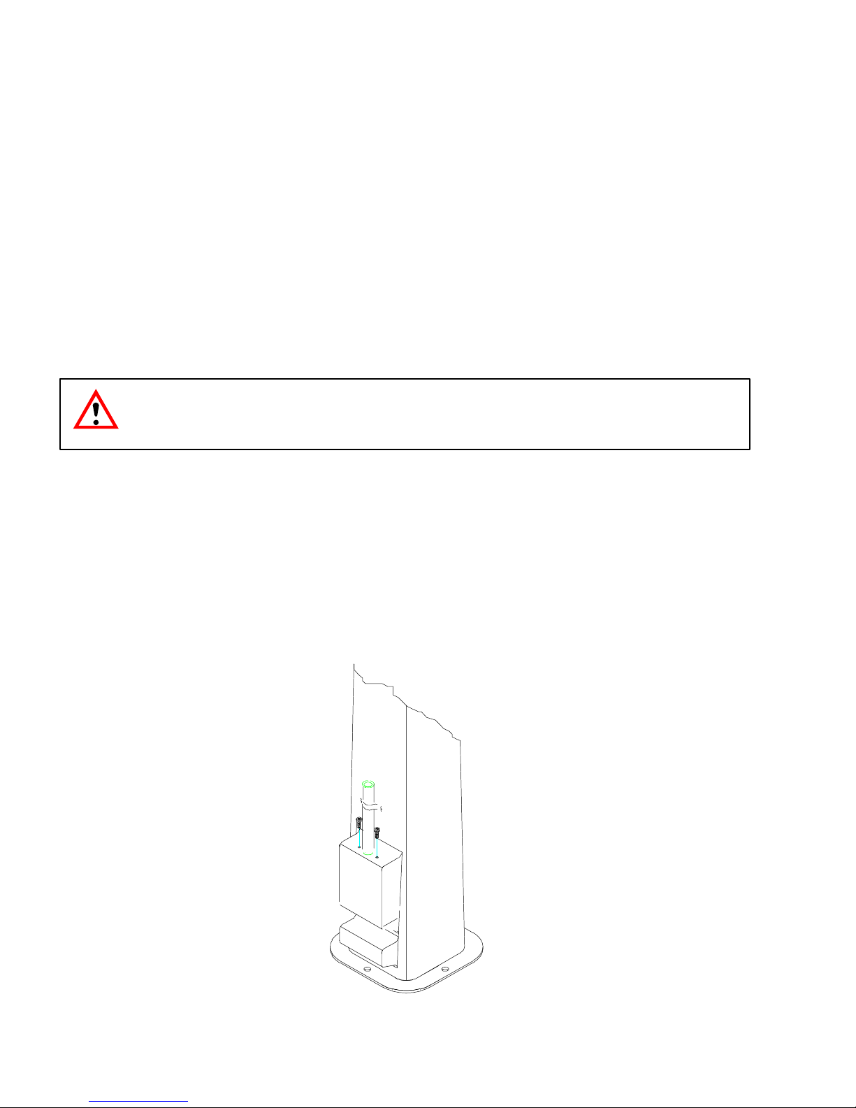
9. Remove the flaker front panel. Position the bin thermostat in place and install the hold down screws as
shown in Figure 1.
FIGURE 1. BIN THERMOSTAT INSTALLATION
630460004
2
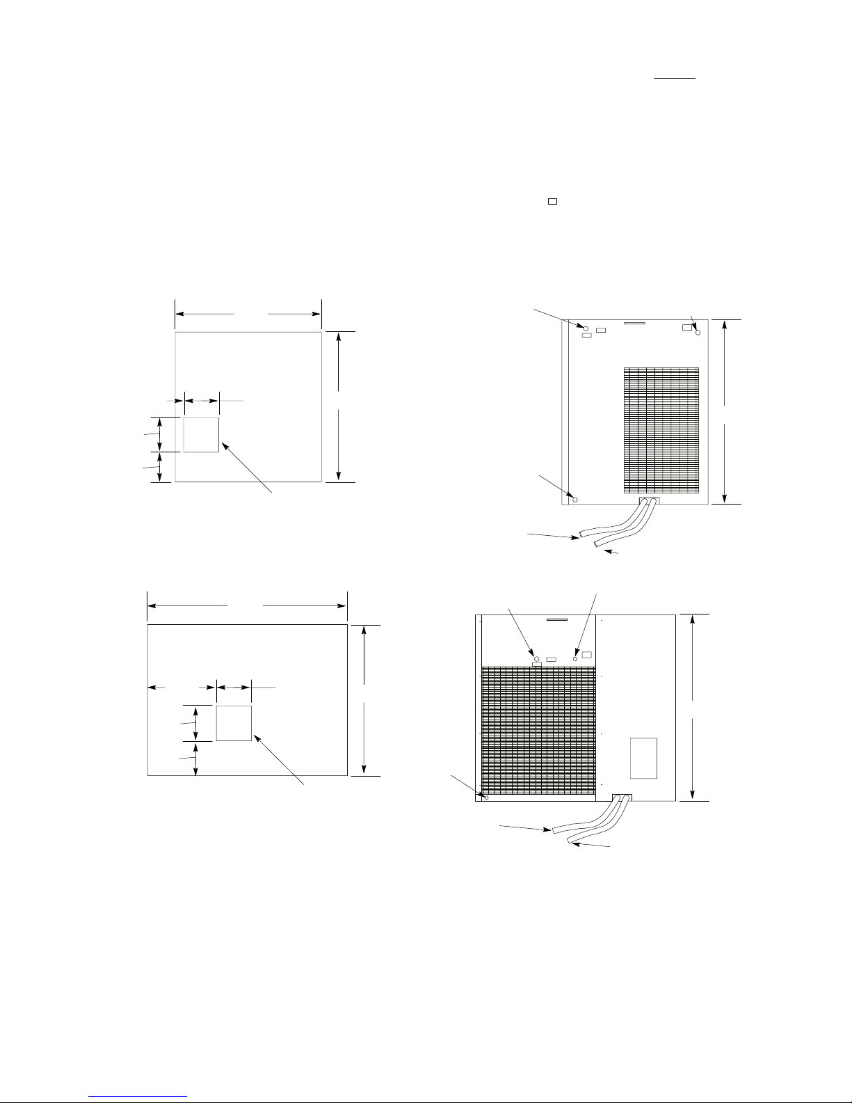
10. The incoming water for the ice making section requires a 3/8” copper tube. Connect this water tube to the
3/8” male flare fitting on the back of the unit. Make all drain connections. Drain tubes cannot
be teed
together. See Figure 2 for location of all plumbing connections.
NOTE: For water cooled units, a separate 3/8” copper water line is required to be connected to the flare
fitting on the back of the unit marked condenser water in. A 3/8” flare connected line will have
to be provided from the fitting marked condenser water out to the drain.
A water regulating valve installed at the factory was set to maintain 290 to 310 PSI head pressure for R–404a
units. After 10 minutes of operation check the water temperature at condenser outlet and adjust to 100_F,
ill371
105_F if necessary.
11. Connect a drain hose to the condensate drain stub tube.
NOTE: All plumbing must be done in accordance with national and local codes.
5.25
4.50
1.25
FRONT SIDE
BOTTOM VIEW
30.00
10.31 5.25
5.25
22.00
5.25
ICE DROP
OPENING
ELECTRICAL SERVICE
OPENING(7/8-IN. DIA. HOLE)
22.60
DUMP VALVE DRAIN HOSE
(9/16-IN. I.D. BY 3/4-IN. O.D.)
IAF 650
ELECTRICAL SERVICE
OPENING(7/8-IN. DIA. HOLE)
22.63
POTABLE WATER INLET
(3/8-IN. MALE FLARE)
27.83
CONDENSER
DRAIN
REAR VIEW
GEABOX/WTRPN DRAIN HOSE
(9/16-IN. I.D. BY 3/4-IN. O.D.)
POTABLE WATER INLET
(3/8-IN. MALE FLARE)
27.83
5.20
FRONT SIDE
BOTTOM VIEW
12. Bring the electrical supply (20 Amp.) into the unit at the rear of the cabinet and enters the unit control box.
The power and ground connections are completed to the leads in the control box. Strain relief connections
must be made at the cabinet and at the control box.
NOTE: Make sure the proper voltage and number of wires are provided. See serial plate for proper
configuration.
NOTE: All wiring must conform to national and local codes.
CONDENSER
DRAIN
ICE DROP
OPENING
DUMP VALVE DRAIN HOSE
(9/16-IN. I.D. BY 3/4-IN. O.D.)
IAF 1000
FIGURE 2. SERVICE CONNECTIONS
3 630460004
REAR VIEW
GEABOX/WTRPN DRAIN HOSE
(9/16-IN. I.D. BY 3/4-IN. O.D.)
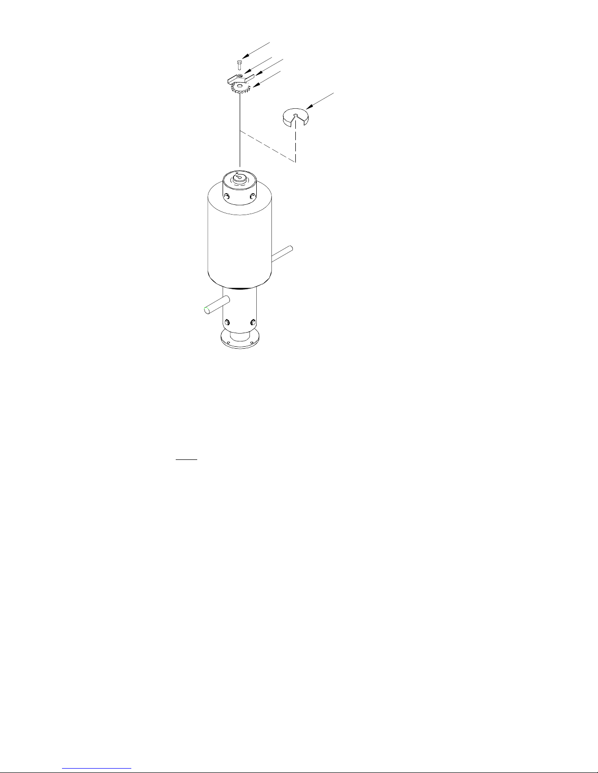
1
2
3
4
5
1. Remove the chute from the evaporator assembly
2. Remove item 1, .50-20 x 1.25 bolt; item 2, .50 lockwasher; item 3, ice paddle, and item 4,
flaker cutter head.
3. Install item 5, nugget ice cutter head, and re-install items 1, 2, & 3
4. Re-install chute. (RTV must be used around the base of the chute.)
FIGURE 3. INSTRUCTIONS FOR CONVERTING FLAKED ICE TO NUGGET ICE.
630460004
4
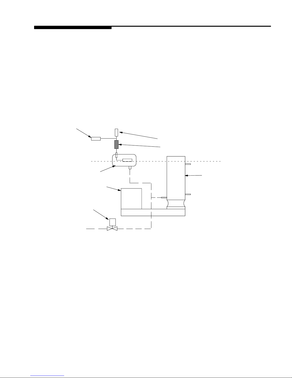
W ATER AND ICE CIRCUIT
The supply water enters the float chamber through a small orifice. The water level rises and lifts the float arm on
the float valve and seats the valve, shutting off the water supply when the water is at the desired level. As the
water leaves the float chamber, filling the evaporator, the float drops and allows additional water to enter refilling
the float chamber. Thus the water level is maintained automatically as the unit operates.
The water level in the evaporator shell will rise to the same level as the water in the float chamber. The water in
direct contact with the evaporator wall freezes and forms ice on the evaporator wall. As the freezing continues
the ice becomes thicker and exceeds the space between the evaporator wall and the auger. The auger rotating
at 8 RPM then chips off the ice and moves it to the surface of the shell. When the ice reaches the top surface of
the water in the shell it is pushed upward through the extruder opening into the cutter heads. From the cutter
head the ice enters the drop chute and falls into the storage bin. This action continues until the ice comes in
contact with the bin thermostat and the unit is shut down. The unit will remain off until the ice drops from the bin
thermostat through consumption or melting, at which time the unit will restart.
Water Inlet Fitting
Water Pressure Switch
Strainer
Float Valve
Gear Motor
Water Dump Valve
Water Level
Evaporator
FIGURE 4. WATER LEVEL
5 630460004

“I” SERIES FLAKER CLEANING
AND SANITIZING PROCEDURE
1. To eliminate water from entering the reservoir, block up the float located inside the reservoir, activate the
dump switch to the “ON” position and turn the power switch to “ON”. Allow the evaporator to drain. Turn the
power switch to the “OFF” position.
2. Remove the ice chute by removing the hold-down nuts at the base and the self-clamping bolt at the top. Lift
the chute clear of the evaporator assembly.
3. Return the float to it’s normal position. As the float chamber refills with water and fills the evaporator, add 3
oz. of Calgon Nickel-Safe ice machine cleaner to the float chamber. (Gravity will feed the cleaner to the
evaporator.)
NOTE: Do not remove the auger, extruder head, or other parts from the evaporator assembly.
4. Allow the cleaning solution to stand in the evaporator for 20 - 30 minutes. Block up the float and drain the
evaporator as in step 1.
5. Rinse/flush by carefully filling with warm water (100_F) and drain by following step 1 again. Repeat at least
3 times. During the final rinse/flush cycle, add 1 tablespoon of regular Baking Soda and allow it to stand for
10 - 15 minutes.
6. Drain the evaporator and rinse/flush one more time.
7. Install the ice chute and panels. (RTV must be used around the base of the chute.)
CAUTION: Should sanitizing be required, DO NOT use a mixture of household bleach and
water Chlorine will attack stainless steel. Use only a commercial ice machine sanitizer such
as Calgon Sanitizer for ice machines, following the directions on the container.
NOTE: When cleaning and/or sanitizing is complete return the machine back to an ice making cycle.
Discard the first 30 minutes of ice production. DO NOT allow any ice that has been in contact
with sanitizer to ever be used.
630460004
6
WATER TREA TMENT
During the freezing process, as water passes over the evaporator, the impurities in the water have a tendency
to be rejected and the plate will freeze only the pure water.
However, the more dissolved solids in the water, the more troublesome the freezing operation will be. Bicarbonates in the water are the most troublesome of the impurities. These impurities will cause scaling on the evaporator, clogging of the float valve mechanism and other parts in the water system. If the concentration of impurities is high, mushy ice may be the result.
Parts of the Flaker, that are in contact with the water or ice, may corrode if the water is high in acidity. In some
areas, water may have to be treated in order to overcome some of the problems that arise because of the mineral content.
IMI Cornelius has water filter/treatment systems available to control impurities found in most water supplies.
Contact your local dealer for more information.
WINTER STORAGE
If the unit is to be stored in an area where the temperature will drop below freezing, it is most important that all
water lines be drained to prevent them from freezing and possible rupture.
To blow out the water line, disconnect the water supply at the cabinet inlet and use air pressure to force the water into the water reservoir pan, it can then be removed from the water pan.
WATER COOLED CONDENSER – To remove water from condenser unhook water supply and attach compressed air hose. Start machine. As head pressure reaches the appropriate level opening the water regulating
valve, the compressed air will force the water out. Do not let the machine operate longer than necessary.
CLEANING THE CONDENSER (AIR COOLED)
In order to produce at full capacity, the refrigeration condenser must be kept clean. The frequency of cleaning
will be determined by surrounding condition. A good maintenance plan calls for an inspection at least every two
months.
With a vacuum cleaner, remove all accumulated dust and lint that has adhered to the finned condenser at the
rear of the unit. The use of a stiff bristle brush may be helpful.
CAUTION: CONDENSER COOLING FINS ARE SHARP. USE CARE WHEN CLEANING.
7 630460004

BL
RD
RD
M
RD
YL
CONDENSER
FAN MOTOR
CONTROL
LOW PRESSURE
C.I. 20 PSIG
C.O. 10 PSIG
T/D
3
COMPRESSOR
START
CAPACITOR
145-174MFD 250V35MFD 370V
1
5
2
M
RD
1
WH
OR
RD
GW
BK
BK
RD
BL
BIN
THERMOSTAT
RD
BL
CONTROL
HIGH
BL
BK
RD
PRESSURE
C.O. 450 PSIG
WATER DUMP
SWITCH
2
1 3
BL
CONTACTOR
RD
BK
BL
BK
THERMOSTAT
ON-OFF SWITCH
CIRCUIT BREAKER
RATED 1.5 AMPS
DELAY
BK
WATER DUMP
VALVE
COMPRESSOR
BR
RD
BK
FAN SWITCH
CI 275
CO 205
BL
GEAR MOTOR
START RELAY
GEAR
3
BK
2
RD
R
C
S
BK
RD
YL
YL
4
BK
WH
COMPRESSOR
RUN
CAPACITOR
COMPRESSOR
START RELAY
BKBK
BK
RD
208/230 VOLTS 60 Hz
FIGURE 5. WIRING DIAGRAM IAF1000
630460004
8

Crankcase Heater
(IRF Only)
BK
BL
RD
RD
BK
BK
RD
BK
GW
BL
RD
BL
BL
Bin
Thermostat
RD
Control
High Pressure
CO 450 PSIG
Water Dump
Switch
2
1
3
BL
RD
BK
BL
BK
Contactor
BK
ON-OFF Switch
Circuit Breaker
Rated 1.5 Amps
Delay
Thermostat
BK
Water Dump
Valve
Compressor
RD
BR
BK
Control
Low Pressure
CI 20 PSIG
CO 10 PSIG
BL
Gear Motor
Start Relay
YL
BK
T/D
M
BK
BK
M
Cooling Fan
Motor
RD
Compressor Run
Capacitor
35MFD 370 V
R
C
S
RD RD
YL YL
BK
Compressor
Start Relay
BK
WH
Compressor Start
Capacitor
145-174MFD 250 V
OR
BK
RD
WH
RD
FIGURE 6. WIRING DIAGRAM IWF1000 AND IRF1000
Liquid Line
Solenoid
(IRF Only)
RD
RD
9 630460004

BK
WH
BK
GW
BL
RD
BK
BIN
THERMOSTAT
RD
BK
CONTROL
LOW PRESSURE
C.I. 20 PSIG
C.O. 10 PSIG
BL
BL
DELAY
THERMOSTAT
BK
22i
21
BL
BK
WH
12k
ON–OFF SWITCH
CIRCUIT BREAKER
RATED 2.0 AMPS
11
GEAR MOTOR
START RELAY
3
2
YL
4
BK
GEAR
M
WH
WH
3
T/D
WH
WH
1
BK
BK
BL
CONTROL
HIGH
WATER DUMP
BL
SWITCH
PRESSURE
C.O. 450 PSIG
2
1
3
BL
BK
WH
CONTACTOR
BK
WATER DUMP
VALVE
BL
BR
COOLING
FAN MOTOR
IWF ONLY
WH
WH
LOW AMBIENT
SWITCH (A/C ONLY)
CI275 C0205
R
C
S
COMPRESSOR
BR
RD RD
YL
COMPRESSOR
START RELAY
M
RUN
COMPRESSOR
CAPACITOR CAPACITOR
30MFD 440V
BK
M
CONDENSOR FAN MOTOR
(A/C ONLY)
COMPRESSOR
YL
1
5
2
BKBKBK
START
OR
WH
FIGURE 7. WIRING DIAGRAM IAF650 AND IWF650
630460004
10

“I” Series “Remote”
Ice Machine
Remote Condenser Specifications
Model CR800
Volts 230
Phase 1
Hertz 60
Amps 1.0
Output, HP 1/6
Max, fuse size, Amps (HVAC circuit breaker
required)
20
11 630460004

630460004
12

BK
M
CAPACITOR
2 mfd 440 VAC
RED
COLORED
BAND
BK
HEAT SHRINK
TAPE
GR
FAN CYCLING
SWITCH
CONDENSER
FAN MOTOR
HEAT SHRINK TAPE
BK
HEAT SHRINK TAPE
CR800, CR1200, & CR1400 REMOTE CONDENSERS
RD
GR
208/230 VOLTS 60 HZ
13 630460004

Installation Instructions Remote Condensers
UNIT
LEG
1/4-20 SCREW
LEG
BRACE
1. Follow the standard installation instructions supplied with
flaker. Do not hook flaker into the power source until the remote condenser and line set installation is complete.
2. Assembly of remote condenser (see drawing):
a. Assemble legs to base panel.
Install leg supports on legs.
b. Locate the remote condenser in a well–ventilated area
on the roof away from other refrigeration equipment’s
condenser discharge air flow.
c. Use the mounting holes provided to secure the remote
condenser to the roof. Seal over heads of bolts or fasteners with tar or pitch to prevent entrance of moisture.
LEG SUPPORT
REMOTE CONDENSER
3. Remote condenser electrical hook-up:
a. Connect remote condenser to a power source
(208/230VAC, 60 HZ) separate from the flaker. An external disconnect switch must be used.
b. Make sure the electrical connections follow all local and
national codes.
c. DO NOT turn condenser on until flaker install and re-
frigerant line connections are complete!
a. Never wire condenser into flaker section. The con-
denser is an independent electrical connection.
b. Fan motor will not start until pressure rises to 205
PSIG [14.07 Bars] closing fan cycling switch.
c. The condenser fan may cycle off during the harvest
cycle – this would be normal.
Note: Installing an IMI Cornelius remote flaker with other
than an IMI Cornelius remote condenser and line set
may be reason to void the warranty.
LEG
630460004
14

LIQUID
REFRIGERANT
LINE
DISCHARGE
LINE
4. Each condenser and flaker is connected with two (2) *precharged lines.
a. The pre-charged lines are ordered separately from the
condenser to suit each individual application.
b. The pre-charged line lengths are 20 feet [6.096 meters],
35 feet [10.66 meters] and 55 feet [16.76 meters].
Note: *(Pre-charged is defined as a vapor holding charge –
not a portion of the system charge.)
5. Installation of line kits (see drawing). Remove the tubing
from the carton. Carefully uncoil the lines so the tubing
doesn’t become kinked, and route lines to flaker and condenser.
6. Keep line-set as short as possible. Place a 3-foot service
loop behind flaker to allow for rear service should it ever be
required.
CORRECT
15 630460004

Remote Condenser Location
1. Physical Line-Set Length: 55 Ft. Maximum [16.764 me-
ters]
The ice machine compressor must have the proper oil return. Line-set rises, drop, or horizontal runs greater than the
maximum distance allowed will exceed the compressor startup and pumping design limits, and will result in poor oil return to the compressor.
NOTE: MAX. LINE-SET
LENGTH FOR IMI CORNELIUS
FLAKERS IS 55 FT.
DO NOT CONFUSE LINE
LENGTH WITH CALCULATED
LINE DISTANCE.
Line-Set Rise: 35 Ft. Maximum [10.66 meters]
Line-Set Drop: 15 Ft. Maximum [4.57 meters]
2. Calculated Line-Set Distance: 100 Ft. [30.48 meters]
To prevent the combination of rises, drops and horizontal
runs exceeding the compressor start-up and pumping design
limit, the following calculations should be made:
B
A
C
B
A - (RISE) CONDENSER HIGHER THAN EVAP.
MAX. 35 FT.
B - LINE LENGTH 15 FT.: EXAMPLE
630460004
B - LINE LENGTH 35 FT.: EXAMPLE
C - (DROP) CONDENSER LOWER THAN EVAP. 15 FT.: MAX.
16

Maximum Line-Set Distance Formula
a. Measured rise x 1.7= Calculated
Rise 35 ft. Max) [10.66 meters]
b. Measured drop x 6.6= Calculated
Drop 15 ft. Max) [4.57 meters]
c. Measured Horizontal Distance = actual measurement.
d. Total Calculated Distance (A+B+C)=Total
Calculated Distance (100 ft. Max.) [30.48 meters]
H
COMBINATION OF
DROP(S)
WITH HORIZONTAL
COMBINATION OF RISE AND
DROP(S)WITH HORIZONTAL
H
H
R
EXAMPLES:
AIR
FLOW
R
a. Insert measured rise (R) into the formula and multiply
it by 1.7 to get a calculated rise.
example: A condenser located 15 ft. [4.572 meters]
above the ice machine has a 25.5 ft. [8.874 meters]
calculated total (15 ft. x 1.7 = 25.5).
b. Insert measured drop (D) into formula and multiply by
6.6 to get a calculated drop.
D
AIR
FLOW
example: A condenser located 8 ft. [2.438 meters]
below the ice machine has a 52.8 ft. [16.093 meters]
calculated total (8 ft. x 6.6 = 52.8 ft.).
c. Insert measured horizontal distance into formula. No
calculation is necessary. (6 ft.) [1.828 meters].
D
AIR
FLOW
d. Add the calculated rise, calculated drop, and hori-
zontal distance together to get the total calculated
distance (25.5 + 52.8 + 6) equals 84.3 ft. [25.694 meters]. If 100 ft. [30.48 meters] total calculated distance is exceeded, the condenser must be moved to
a new location which permits proper equipment operation.
Caution
If a line-set rise is followed by a line-set drop, a second
line-set rise cannot be made.
Or
If a line-set drop is followed by a line-set rise, a second
line-set drop cannot be made.
3. Lengthening or Reducing the Line-Set Lengths
In most cases, by routing the line-set properly, shortening
17 630460004

will not be necessary (refer to illustration). However, when
shortening or lengthening is required, do so before connecting the line-set to the ice machine or the remote condenser.
This prevents the loss of refrigerant from the ice machine or
the condenser.
The quick connect fittings on the line-sets are equipped with
Schrader Valves. Use these valves to recover any vapor
charge from the line-set. When lengthening or shortening
lines, apply good refrigeration practices and insulate new
tubing. Do not change the tube sizes. Evacuate the lines
and place approximately 5 oz. of
vapor refrigerant charge in each line.
SCHRADER
VALVE
PARENT
METAL
SEAL
INTERMEDIATE
SEAL
4. Connection of Line-Set
a. Remove the plastic caps from the line-set, the condens-
er, and the ice machine.
b. Apply refrigeration oil to the threads on the quick connect
couplers before connecting them to the condenser.
c. Carefully thread the female fitting onto the condenser or
ice machine by hand.
d. Using the proper size wrench, tighten the couplings until
they bottom out. Turn an additional 1/4 turn to ensure
proper brass-to-brass seating.
e. Check all fittings for leaks.
5. Final Installation:
a. Remove grill from the right-hand side panel of flaker.
b. Turn service port on receiver tank to open position re-
leasing refrigerant to the balance of the system.
c. Leak check line-set connections at flaker and condenser.
d. Replace grill.
e. Connect flaker to power source.
f. Make sure electrical connections follow all local and na-
tional codes.
Caution
630460004
6. Start Up:
a. Use standard procedures from flaker installation instruc-
tions.
b. After the flaker is running, check the remote condenser
and verify that the condenser fan is running.
Once the refrigerant lines are connected, the seal is broken in
the fittings. If the lines are removed or loosened from the flaker
or remote condenser, the refrigerant charge will be discharged
to the atmosphere. DISCHARGING TO THE ATMOSPHERE IS IN
VIOLATION OF THE CLEAN AIR ACT OF JULY, 1992.
18

discharge
Head Pressure Control [Headmaster]
The Cornelius “I” series remote systems use an Alco Head Pressure
Control, normally referred to as a headmaster. This control is
mounted in the remote condenser with a fan cycling control switch.
Using both these controls gives the system positive operation under
a wide range of condensing temperatures.
The cycling control starts the fan at 270 PSI and stops it at 205 PSI
allowing a positive efficient operation at the high temperature operating ranges.
The headmaster controls the operation when the condensing tem-
receiver
condenser
above 70°F
normal
perature drops below 70°F. The “I” series refrigerant charge is HP 62 [R - 404A] and the headmaster dome charge setting is 200 PSI
of nitrogen pressure making it stable under the low temperature operating range down to - 20°F.
The normal flow pattern through the headmaster is from the condenser port to the receiver port. When this flow pattern is unable to
maintain a receiver outlet pressure equal to or above the dome
pressure setting of the valve, the dome pressure will force the valve
portage to change closing the condenser port and opening the bypass port from the compressor discharge line. This allows the high
pressure vapor from the discharge port to “buck” the receiver pressure back up. With the condenser port closed, the refrigerant is
backed up in the condenser, basically reducing the condenser size,
assisting in maintaining the discharge portage flow and increasing
the head pressure.
discharge
condenser
below 70°F by-pass
receiver
Remember, sense of touch to the lines of the headmaster will determine the flow path the headmaster is in, condenser to receive, or
bypass to receiver.
High side gauge installed at the receiver outlet valve will determine
if the headmaster is functioning to maintain the proper operating
pressure.
In the event the control appears to be “stuck in bypass”, the pressure drop across the headmaster must be measured. With a gauge
installed at the receiver outlet valve and the high side service valve,
the pressure difference at these two points must be less than the 15
PSI. The three most common causes of an excessive pressure drop
are shortage of refrigerant, kinked remote lines, and excessive line
length.
Eliminate refrigerant shortage first. Add refrigerant in two-pound increments (not to exceed six pounds) to determine if it corrects the
pressure drop. If pressure drop is not corrected, inspect line set for
sharp bends or kinks and correct as required. If adding refrigerant
does not correct continued (bypass) condition and line set is not
damaged, replace headmaster.
19 630460004

Remote System Evacuation/Re-charge
All field repairs to the sealed system must start with a total discharge of the system following the requirements of the Clean Air Act
of July, 1992.
Proper evacuation of the total remote system will require a three (3)
point hook-up of your manifold and hose set, (see drawing):
Point #1 - flaker receiver outlet valve
Point #2 - flaker high side service valve
Point #3 - flaker low side service valve
Evacuation:
1. With flaker power supply turned “OFF” disconnect and insu-
late all 3 compressor leads at the compressor. Turn power
supply on, place power switch in the “on” position. This will
energize (open) the Liquid Line solenoid allowing evacuation
of the Liquid Line between the solenoid and the expansion
valve(s).
2. Evacuate system to 200/250 microns or less. At this point,
there should be a holding test of five(5) minutes. You may
expect a slight loss of vacuum as normal. A rapid rise to normal atmospheric pressure indicates moisture still present in
the system. On a “wet” system, it will prove beneficial to use
heat lamps to warm the compressor dome and evaporator
surface during evacuation.
3. Turn flaker power switch OFF. Reconnect compressor leads.
630460004
20

OPEN
EVACUATION
MANIFOLD SET
OPEN
1ST STAGE CHARGING
MANIFOLD SET
OPEN
CLOSED
2ND STAGE CHARGING
COMPRESSOR OPERATING
CLOSED
MANIFOLD SET
OPEN
RECEIVER
OPEN
RECEIVER
OUTLET
VALVE
VACUUM
PUMP
OPEN
OPEN
CHARGING
CYLINDER
CLOSED
HIGH SIDE
SERVICE
VALVE
LOW
SIDE
SERVICE
VALVE
CLOSED
ELECTRONIC
SCALE
RECEIVER
OPEN
RECEIVER
OUTLET
VALVE
VACUUM
PUMP
CLOSED
CLOSED
OPEN
CHARGING
CYLINDER
OPEN
ELECTRONIC
HIGH SIDE
SERVICE
VALVE
LOW
SIDE
SERVICE
VALVE
SCALE
RECEIVER
CLOSED
RECEIVER
OUTLET
VALVE
VACUUM
PUMP
CLOSED
CLOSED
HIGH SIDE
SERVICE
VALVE
LOW
SIDE
SERVICE
VALVE
OPEN
CHARGING
CYLINDER
OPEN
ELECTRONIC
SCALE
21 630460004

4. *After proper evacuation hold test has been performed, the
refrigerant charge should be “dumped” into the receiver until
the pressure equalizes, stopping the flow. Do not try to
throttle the refrigerant flow. Doing so will allow system
pressure to balance too soon. The high-side service valve
should be closed and the balance of the charge fed slowly
through the suction side service valve with the compressor
operational. Control the feed rate at no faster than four (4)
ounces [113.g] per minute to ensure the compressor oil does
not become too saturated with refrigerant resulting in a loss
of compressor lubrication.
5. All refrigerant re-charging must be weighed into the system,
utilizing an electronic charging scale. DO NOT attempt to
recharge the system by sight glass, system pressure, amperage, frost line or sweat patterns.
6. Always leak check entire system after recharge.
Caution
Before programming the electronic scales to “dump” the
charge,
de-energize the liquid line solenoid, close the shut-off valve on
vacuum pump and low side of the manifold set.
630460004
22

IMI CORNELIUS INC.
Corporate Headquarters:
Anoka, Minnesota 55303-6234
One Cornelius Place
(612) 421-6120
(800) 238-3600
 Loading...