

Cornelius IACS224E50, IWCS224, IWCS224E50 Installation Manual
IMI CORNELIUS INC g One Cornelius Place g ANOKA, MN 55303–6234
Telephone (800) 238–3600 Facsimile (800) 535–4231
Installation Manual
“I” Series 224
Ice Cube Machine
IMPORTANT:
TO THE INSTALLER.
It is the responsibility of
the Installer to ensure that
the water supply to the
dispensing equipment is
provided with protection
against backflow by an air
gap as defined in
ANSI/ASME A112.1.2-1979;
or an approved vacuum
breaker or other such
method as proved effective
by test.
Water pipe connections
and fixtures directly
connected to a potable
water supply shall be
sized, installed, and
maintained according to
Federal, State, and Local
Codes.
Part No. 630460070
June 13, 1998
Revised October 9, 2003
Revision B
Control Code A
THIS DOCUMENT CONTAINS IMPORTANT INFORMATION
This Manual must be read and understood before installing or operating this equipment
IMI CORNELIUS INC; 1998–2003
PRINTED IN U.S.A

TABLE OF CONTENTS
SAFETY INFORMATION 1. . . . . . . . . . . . . . . . . . . . . . . . . . . . . . . . . . . . . . . . . . . . . . . . . . . .
RECOGNIZE SAFETY INFORMATION 1. . . . . . . . . . . . . . . . . . . . . . . . . . . . . . . . . .
UNDERSTAND SIGNAL WORDS 1. . . . . . . . . . . . . . . . . . . . . . . . . . . . . . . . . . . . . . .
FOLLOW SAFETY INSTRUCTIONS 1. . . . . . . . . . . . . . . . . . . . . . . . . . . . . . . . . . . .
CO2 (CARBON DIOXIDE) WARNING 1. . . . . . . . . . . . . . . . . . . . . . . . . . . . . . . . . . .
SHIPPING, STORING, OR RELOCATING UNIT 1. . . . . . . . . . . . . . . . . . . . . . . . . .
GENERAL DESCRIPTION 3. . . . . . . . . . . . . . . . . . . . . . . . . . . . . . . . . . . . . . . . . . . . . . . . . .
FREIGHT DAMAGE CLAIMS PROCEDURE 3. . . . . . . . . . . . . . . . . . . . . . . . . . . . . .
SPECIFICATIONS, ICE CUBER 3. . . . . . . . . . . . . . . . . . . . . . . . . . . . . . . . . . . . . . . . .
INSTALLATION 5. . . . . . . . . . . . . . . . . . . . . . . . . . . . . . . . . . . . . . . . . . . . . . . . . . . . . . . . . . . .
LOCATION OF EQUIPMENT 5. . . . . . . . . . . . . . . . . . . . . . . . . . . . . . . . . . . . . . . . . . . .
PLUMBING CONNECTIONS 5. . . . . . . . . . . . . . . . . . . . . . . . . . . . . . . . . . . . . . . . . . . .
ELECTRICAL 7. . . . . . . . . . . . . . . . . . . . . . . . . . . . . . . . . . . . . . . . . . . . . . . . . . . . . . . . .
INSTALLATION CHECK POINTS. 7. . . . . . . . . . . . . . . . . . . . . . . . . . . . . . . . . . . . . . . .
START-UP AND CHECK OUT 8. . . . . . . . . . . . . . . . . . . . . . . . . . . . . . . . . . . . . . . . . . .
OWNER-OPERATOR 9. . . . . . . . . . . . . . . . . . . . . . . . . . . . . . . . . . . . . . . . . . . . . . . . . . . . . . .
Page
CLEANING PROCEDURES 9. . . . . . . . . . . . . . . . . . . . . . . . . . . . . . . . . . . . . . . . . . . . .
PREP-CLEANING 9. . . . . . . . . . . . . . . . . . . . . . . . . . . . . . . . . . . . . . . . . . . . . . . . . . . . .
CLEANING THE WATER SYSTEM AND EVAPORATOR 9. . . . . . . . . . . . . . . . . . . .
SANITIZING PROCEDURES 10. . . . . . . . . . . . . . . . . . . . . . . . . . . . . . . . . . . . . . . . . . . .
DUMP CYCLE 10. . . . . . . . . . . . . . . . . . . . . . . . . . . . . . . . . . . . . . . . . . . . . . . . . . . . . . . . .
CIRCUIT BOARD SETTING 11. . . . . . . . . . . . . . . . . . . . . . . . . . . . . . . . . . . . . . . . . . . . .
ADJUSTING BRIDGE THICKNESS 12. . . . . . . . . . . . . . . . . . . . . . . . . . . . . . . . . . . . . .
HARVEST CONTROL 13. . . . . . . . . . . . . . . . . . . . . . . . . . . . . . . . . . . . . . . . . . . . . . . . . .
FULL BIN CONTROL 13. . . . . . . . . . . . . . . . . . . . . . . . . . . . . . . . . . . . . . . . . . . . . . . . . . .
WARRANTY 14. . . . . . . . . . . . . . . . . . . . . . . . . . . . . . . . . . . . . . . . . . . . . . . . . . . . . . . . . . . . . .
LIST OF FIGURES
FIGURE 1. INSTALLATION 5. . . . . . . . . . . . . . . . . . . . . . . . . . . . . . . . . . . . . . . . . . . . .
FIGURE 2. CUBER INSTALLATION 6. . . . . . . . . . . . . . . . . . . . . . . . . . . . . . . . . . . . . .
FIGURE 3. SINGLE EVAPORATOR WATER LEVEL 7. . . . . . . . . . . . . . . . . . . . . . . .
FIGURE 4. ELECTRICAL BOX SWITCH PANEL 8. . . . . . . . . . . . . . . . . . . . . . . . . . .
FIGURE 5. FLOW CONTROL WASHER 11. . . . . . . . . . . . . . . . . . . . . . . . . . . . . . . . . .
FIGURE 6. DUMP CYCLE OPTIONS 12. . . . . . . . . . . . . . . . . . . . . . . . . . . . . . . . . . . . .
FIGURE 7. CUBE SEPARATION 12. . . . . . . . . . . . . . . . . . . . . . . . . . . . . . . . . . . . . . . . .
i
630460070
SAFETY INFORMATION
Recognize Safety Information
This is the safety-alert symbol. When you see this
symbol on our machine or in this manual, be alert to
the potentially of personal injury.
Follow recommended precautions and safe operating
practices.
Understand Signal Words
A signal word - DANGER, WARNING, OR CAUTION
is used with the safety-alert symbol. DANGER identi-
fies the most serious hazards.
DANGER
Safety signs with signal word DANGER or WARNING
are typically near specific hazards.
General precautions are listed on CAUTION safety
signs. CAUTION also calls attention to safety messages in this manual.
WARNING
CAUTION
Follow Safety Instructions
Carefully read all safety messages in this manual and on your machine safety signs. Keep safety signs in
good condition. Replace missing or damaged safety signs. Learn how to operate the machine and how to
use the controls properly. Do not let anyone operate the machine without instructions. Keep your machine in
proper working condition. Unauthorized modifications to the machine may impair function and/or safety and
affect the machine life.
CO2 (Carbon Dioxide) Warning
CO2 Displaces Oxygen. Strict Attention must be observed in the prevention of CO2 (carbon dioxide)
gas leaks in the entire CO2 and soft drink system. If a CO2 gas leak is suspected, particularly in a
small area, immediately ventilate the contaminated area before attempting to repair the leak. Personnel exposed to high concentration of CO2 gas will experience tremors which are followed rapidly by
loss of consciousness and suffocation.
Shipping, Storing, Or Relocating Unit
CAUTION: Before shipping, storing, or relocating this Unit, the syrup systems must be sanitized and
all sanitizing solution must be purged from the syrup systems. All water must also be purged from
the plain and carbonated water systems. A freezing ambient temperature will cause residual water
remaining inside the Unit to freeze resulting in damage to internal components of the Unit.
1 630460070

THIS PAGE LEFT BLANK INTENTIONALLY
2630460070
GENERAL DESCRIPTION
This section gives the Unit description, theory of operation, and design data for
IMPORTANT: To the user of this manual – This manual is a guide for installing, operating, and maintaining this equipment. Refer to the Table of Contents for page location for detailed information pertaining to questions that arise during installation, operation, service, or maintenance of this equipment.
FREIGHT DAMAGE CLAIMS PROCEDURE
The deliver of your equipment (freight company, distributor, or dealer) is responsible for loss or damage of your
shipment. All claims must be filed with the deliverer of your equipment. Please follow the steps below to determine is your shipment is satisfactory or if a claim must be filed.
1. Check the number of products delivered against the number of products listed on the delivery receipt.
Should the totals not match, have the driver note all error on both copies and both you and the driver sign
and ate said notation.
2. Inspect all cartons for visible damage. Open and inspect as required before the driver leaves and have him
or her note any damage on the receipts. All damaged claims must be inspected within 15 days of delivery.
Notify your carrier immediately if concealed damage is found after delivery.
3. Should concealed damage be found when product is unpacked, retain the packing material and the product
and request an inspection from the deliverer.
4. All claims for loss or damage should be filed at once. Delays in filing will reduce the chance of achieving a
satis factory resolution to the claim.
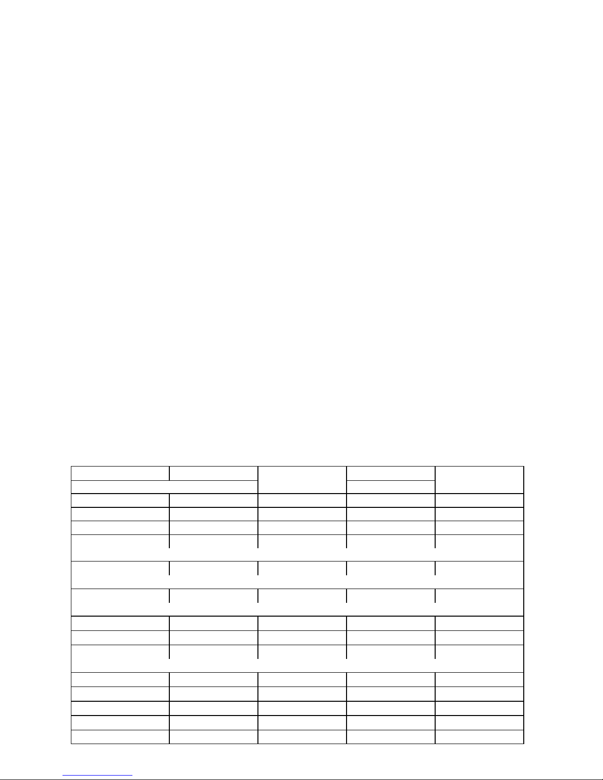
SPECIFICATIONS, ICE CUBER
The following table contains equipment specification information for the Ice Cubers.
MODEL IACS224 IACS224E50 IWCS224 IWCS224E50
UNIT
Volts 115 220 115 220
Phase 1 1 1 1
Hertz 60 50 60 50
No. Wires 2+Ground 2+Ground 2+Ground 2+Ground
MIN. CIRCUIT MAX FUSE SIZE (HVAC CIRCUIT BREAKER REQUIRED)
Amps 20 15 20 15
MAX FUSE SIZE (HVAC CIRCUIT BREAKER REQUIRED)
Amps 20 15 15
REFRIGERANT
Type R404A(HP62) R404A(HP62) R404A(HP62) R404A(HP62)
Weight (oz) 13 13 13 13
Weight (g) 369 369 369 369
COMPRESSOR
Volts 115 220 115 220
Phase 1 1 1 1
Hertz 60 57 60 57
LRA 37.2 16.1 37.2 16.1
RLA 7.1 2.8 7.1 2.8
3
630460070

CONDENSER FAN MOTOR (Air-Cooled Systems only) or
AIR CIRCULATION FAN MOTOR (Water-Cooled and Remote Systems only)
Volts 115 220 115 220
Phase 1 1 1 1
Hertz 60 50 60 50
Amps Running 1.4 1.4 .36 .17
Watts 35 35 6 5
WATER PUMP
Volts 115 220 115 220
Phase 1 1 1 1
Hertz 60 50 60 50
Amps Running .89 .45 .89 .45
HP 1/60 1/50 1/60 1/50
630460070
4
 Loading...