

Cornelius IWC522, IAC330, IWC322, IWC530, IAC630 Pocket Manual
...
ICE MAKER
POCKET GUIDE
“I” SERIES CUBE
ICE MAKERS
IMI CORNELIUS
One Cornelius Place
Anoka, MN 55303
1–800–238–3600
TD 204(Metric)

TABLE OF CONTENTS
introduction 1. . . . . . . . . . . . . . . . . . . . . . . . . . . . . . . . . . . . . .
Original Owner, End-user responsibility 1. . . . . . . . . . . .
Serial Plate Locations 2. . . . . . . . . . . . . . . . . . . . . . . . . . . . . .
Model and Serial Number Defined 2. . . . . . . . . . . . . . . . . . . .
Serial Number Defined After January 1, 1995 3. . . . . . . . . .
Electrical Specification 4-9. . . . . . . . . . . . . . . . . . . . . . . . . . . . .
Remote Condenser 10. . . . . . . . . . . . . . . . . . . . . . . . . . . . . . . . .
ICE CAPACITY INFORMATION 11. . . . . . . . . . . . . . . . . . .
Ice Capacity 11. . . . . . . . . . . . . . . . . . . . . . . . . . . . . . . . . . . . . .
Ice Production Check 11. . . . . . . . . . . . . . . . . . . . . . . . . . . . . .
ADJUSTMENT OF ICE BRIDGE THICKNESS 12. . . . . . . .
Ice production capacities and charts 14-29. . . . . . . . . . . .
IAC322/IAC330 14. . . . . . . . . . . . . . . . . . . . . . . . . . . . . .
IWC322/IWC330 15. . . . . . . . . . . . . . . . . . . . . . . . . . . . .
IAC522/IAC530 16. . . . . . . . . . . . . . . . . . . . . . . . . . . . . .
IWC522/IWC530 17. . . . . . . . . . . . . . . . . . . . . . . . . . . . .
IAC630 18. . . . . . . . . . . . . . . . . . . . . . . . . . . . . . . . . . . . .
IWC630 19. . . . . . . . . . . . . . . . . . . . . . . . . . . . . . . . . . . .
IRC630 20. . . . . . . . . . . . . . . . . . . . . . . . . . . . . . . . . . . . .
IAC830 21. . . . . . . . . . . . . . . . . . . . . . . . . . . . . . . . . . . . .
IWC830 22. . . . . . . . . . . . . . . . . . . . . . . . . . . . . . . . . . . .
IRC830 23. . . . . . . . . . . . . . . . . . . . . . . . . . . . . . . . . . . . .
IAC1230 24. . . . . . . . . . . . . . . . . . . . . . . . . . . . . . . . . . . .
IWC1230 25. . . . . . . . . . . . . . . . . . . . . . . . . . . . . . . . . . .
IRC1230 26. . . . . . . . . . . . . . . . . . . . . . . . . . . . . . . . . . . .
IAC1448 27. . . . . . . . . . . . . . . . . . . . . . . . . . . . . . . . . . . .
IWC1448 28. . . . . . . . . . . . . . . . . . . . . . . . . . . . . . . . . . .
IRC1448 29. . . . . . . . . . . . . . . . . . . . . . . . . . . . . . . . . . . .
Sequence of Operation 30. . . . . . . . . . . . . . . . . . . . . . . . . . . . . .
Component Functions 30. . . . . . . . . . . . . . . . . . . . . . . . . . . . . .
Circuit Board 30. . . . . . . . . . . . . . . . . . . . . . . . . . . . . . . . . . . . .
LED Indicators 31. . . . . . . . . . . . . . . . . . . . . . . . . . . . . . .
LED status indicator chart 32-34. . . . . . . . . . . . . . . . . . . .
Reset Operation 34. . . . . . . . . . . . . . . . . . . . . . . . . . . . . .
Voltage Selector Switch 34. . . . . . . . . . . . . . . . . . . . . . . .
Stacking Cable 34. . . . . . . . . . . . . . . . . . . . . . . . . . . . . . .
Test Plug 34. . . . . . . . . . . . . . . . . . . . . . . . . . . . . . . . . . . .
Dump Cycle Options 35. . . . . . . . . . . . . . . . . . . . . . . . . .
Condenser Fan Cycling Control (Intergal Condenser) 36.
Harvest Safety Termination 36. . . . . . . . . . . . . . . . . . . . .
Circuit Board Diagnosis 36. . . . . . . . . . . . . . . . . . . . . . . .
PAGE
i
TD 204

TABLE OF CONTENTS (CONT’D)
Sensors 37. . . . . . . . . . . . . . . . . . . . . . . . . . . . . . . . . . . . . . . . . .
Sensor [Thermistor] Diagnosis 38. . . . . . . . . . . . . . . . . . . . . . .
Evaporator Switches 39. . . . . . . . . . . . . . . . . . . . . . . . . . . . . . .
Switch Notes 39. . . . . . . . . . . . . . . . . . . . . . . . . . . . . . . . . . . . . .
Voltage Checks 39. . . . . . . . . . . . . . . . . . . . . . . . . . . . . . . . . . . .
Water Regulating Valve 40. . . . . . . . . . . . . . . . . . . . . . . . . . . . .
High Pressure Safety Switch 40. . . . . . . . . . . . . . . . . . . . . . . . .
Float Valve with Flow Washer 41. . . . . . . . . . . . . . . . . . . . . . .
Service Stem Valves 41. . . . . . . . . . . . . . . . . . . . . . . . . . . . . . . .
Thermostatic Expansion Valves 41. . . . . . . . . . . . . . . . . . . . . .
diagnosis 42. . . . . . . . . . . . . . . . . . . . . . . . . . . . . . . . . . . . . . . . .
Starving TXV - Product Symptoms 42. . . . . . . . . . . . . . . . . . .
Flooding TXV - Product Symptoms 42. . . . . . . . . . . . . . . . . . .
Head Pressure Control Valve [Headmaster} Fan Cycle Switch
Contactor Compressor 44. . . . . . . . . . . . . . . . . . . . . . . . . . . . .
Compressor & Starting Component Check-Out Procedure 45
Relay 45. . . . . . . . . . . . . . . . . . . . . . . . . . . . . . . . . . . . . . . . . . . .
Capacitors 46. . . . . . . . . . . . . . . . . . . . . . . . . . . . . . . . . . . . . . .
Compressor 46. . . . . . . . . . . . . . . . . . . . . . . . . . . . . . . . . . . . . .
Moisture Contamination 47. . . . . . . . . . . . . . . . . . . . . . . . . . . .
Wiring Diagrams 49-54. . . . . . . . . . . . . . . . . . . . . . . . . . . .
Troubleshooting 55. . . . . . . . . . . . . . . . . . . . . . . . . . . . . . . . . . .
Cleaning Procedures 59. . . . . . . . . . . . . . . . . . . . . . . . . . . . . . .
Prep – Cleaning 59. . . . . . . . . . . . . . . . . . . . . . . . . . . . . . . . . . .
Cleaning the Water System & Evaporator 59. . . . . . . . . . . . . .
Sanitizing Procedures 60. . . . . . . . . . . . . . . . . . . . . . . . . . . . . .
(Remote Units Only) 43. . . . . . . . . . . . . . . . . . . . . .
Potential – 45. . . . . . . . . . . . . . . . . . . . . . . . . . . . . . . . . . .
Current – 45. . . . . . . . . . . . . . . . . . . . . . . . . . . . . . . . . . . .
PAGE
iiTD 204

introduction
This guide is published as an aid to the Service Technician. It is no t
intended to replace the service manual. In it you will find useful information not found in the service manual. This information will
help you more quickly identify specific problems, however not all
problems or situations may be listed. W e appreciate your comments
or suggestions, or if you have a specific problem not addressed in
this guide or service manual.
Please feel free to contact our service department at:
IMI CORNELIUS
One Cornelius Place
Anoka, MN 55303
1–800–554–3526
The warranty on Cornelius icemakers begins on the date of installation, as reported on the warranty registration card to the original
owner/user. If no warranty card is received by the factory, the date
of shipment from the factory will determine the start of the warranty.
Warranty labor will be paid per the labor rate guide and is subject to
change without notice. Call the Service Department for a copy of the
current Labor Rate Guide and/or applicable Warranty Document
Copy.
ORIGINAL OWNER, END-USER RESPONSIBILITY
1. To verify the equipment installation date by the return
of the warranty registration card to the factory within
five days of the installation.
2. To pay freight or handling charge.
3. To pay for service labor and/or parts required to correct improperly installed equipment. Installation must
comply with the installation instructions.
4. To pay for normal maintenance, adjustments and
cleaning.
5. To pay for service labor and/or parts required to correct unit modification or the use of non-approved remote condensers.
6. To pay for service labor and/or parts required because
of neglect, abuse, misuse, accident, fire, flood, freezing or any act of God.
7. To pay for mileage, truck charges, travel time, premium labor for holidays, weekends or after hours
work, flat rate service call charges, miscellaneous tool
charges, use of diagnostic meters or equipment and all
material not listed on the Warranty Time Rate Guide.
1 TD 204

Serial Plate Locations
Exterior: Left side, Lower Front corner.
Interior: Firewall, Front.
Model and Serial Number Defined
IAC 1230
IAC1230
Product
Identifica-
tion
94 A C E 0000
Year
(the first 2
digits
indicates
year of
produc-
tion)
Month of production code will be:
Note: The letter (I) is not used to avoid being confused with the
number(1)
Product Code:
A = Accessory* D = Dispenser (motel/hotel)
B = Bin (storage) E = External condenser (Remote)
C = Cuber F = Flaker
* Any accessory determined to be required to have a serial number.
A=Air
Cooled
Condenser
W=Water
Cooled
R=Remote
Month
Production
A = January G = July
B = February H = August
C = March J = September
D = April K = October
E = May L = November
F = June M = December
Cuber Series
Product
Code
Manufac-
turing
Tracking
Code
30” Wide
3
5
6
8
10
12
14
Cabinet
22 = 22”
Wide
48 = 48”
wide
Unit
Serial
Number
2TD 204

Serial Number Defined
after January 1, 1995
AF 95 01 BC 0000
Eng
change
level
Engineering change level can be either 1 or 2 digits depending
on the revision level.
Month of production code will be:
01 = January 07 = July
02 = February 08 = August
03 = March 09 = September
04 = April 10 = October
05 = May 11 = November
06 = June 12 = December
Note: The Month must always be 2 digits.
Product Code:
BA = Accessory* BD = Dispenser (motel/hotel)
BB = Bin (storage) BE = External condenser (Remote)
BC = Cuber BF = Flaker
* Any accessory determined to be required to have a serial number.
year Month Product
Code
Unit
Serial
Number
3 TD 204

Electrical Specification
MODEL
UNIT
Volts 115 115 115 115
Phase 1 1 1 1
Hertz 60 60 60 60
No. Wires 2+ground 2+ground 2+ground 2+ground
MIN. CIRCUIT
Amps 20 20 20 20
MAX FUSE SIZE (HVAC CIRCUIT BREAKER REQ)
Amps 20 20 20 20
REFRIGERANT
Type
Weight
(oz)
Weight (g) 482 425 737 652
COMPRESSOR
Volts 115 115 115 115
Phase 1 1 1 1
Hertz 60 60 60 60
LRA 51 51 59 59
RLA 11.5 11.5 11.6 11.6
CONDENSER FAN MOTOR (Air-Cooled System
Y OR
onl
AIR CIRCULATION FAN MOTOR (Water-Cooled
and Remote Systems only)
Volts 115 115 115 115
Phase 1 1 1 1
Hertz 60 60 60 60
Amps
Running
Watts 50 6 50 6
WATER PUMP
Volts 115 115 115 115
Phase 1 1 1 1
Hertz 60 60 60 60
Amps
Running
HP 1/40 1/40 1/40 1/40
IAC322/330IWC322/330IAC522/530IWC522/5
R404a
(HP62)
17 15 26 23
1.7 0.38 1.75 0.38
0.88 0.88 0.76 0.88
R404a
(HP62)
R404a
(HP62)
R404a
(HP 62)
30
4TD 204

5 TD 204
MODEL IAC630 IWC630 IRC630 IAC830 IWC830 IRC830
UNIT ELEC.
Volts 230 230 230 230 230 230
Phase 1 1 1 1 1 1
Hertz 60 60 60 60 60 60
No. Wires 2+ground 2+ground 2+ground 2+ground 2+ground 2+ground
MIN. CIRCUIT
Amps 20 20 20 20 20 20
MAX FUSE SIZE (HVAC CIRCUIT BREAKER REQUIRED)
Amps 20 20 20 20 20 20
REFRIGERANT
Type R404a(HP62) R404a(HP62) R404a(HP62) R404a(HP 62) R404a(HP 62) R404a(HP 62)
Weight (oz) 43 35 170 55 33 170
Weight (g) 1219 992 4820 1559 936 4820
COMPRESSOR
Volts 230 230 230 230 230 230
Phase 1 1 1 1 1 1

6
TD 204
COMPRESSOR (CONT’D)
Hertz 60 60 60 60 60 60
LRA 69 69 69 61 61 61
RLA 8.8 8.8 8.8 12.5 12.5 12.5
CONDENSER FAN MOTOR (Air-Cooled System only) or
AIR CIRCULATION FAN MOTOR (Water-Cooled and Remote Systems only)
Volts 230 230 230 230 230 230
Phase 1 1 1 1 1 1
Hertz 60 60 60 60 60 60
Amps Running 1.09 0.36 0.36 1.09 0.36 0.36
Watts 75 6 6 75 6 6
WATER PUMP
Volts 230 230 230 230 230 230
Phase 1 1 1 1 1 1
Hertz 60 60 60 60 60 60
Amps Running 0.5 0.5 0.5 0.5 0.5 0.5
HP 1/30 1/30 1/30 1/30 1/30 1/30

7 TD 204
MODEL IAC1230 IWC1230 IRC1230 IAC1448 IWC1448 IRC1448
UNIT ELEC.
Volts 230 230 230 230 230 230
Phase 1 1 1 1 1 1
Hertz 60 60 60 60 60 60
No. Wires 2+ground 2+ground 2+ground 2+ground 2+ground 2+ground
MIN. CIRCUIT
Amps 20 20 20 25 25 25
MAX FUSE SIZE (HVAC CIRCUIT BREAKER REQUIRED)
Amps 20 20 20 25 25 25
REFRIGERANT
Type R404a(HP62) R404a(HP62) R404a(HP62) R404a(HP 62) R404a(HP 62) R404a(HP 62)
Weight (oz) 49 45 210 92 44 250
Weight (g) 1389 1276 5954 2608 1247 7088
COMPRESSOR
Volts 230 230 230 230 230 230
Phase 1 1 1 1 1 1

8
TD 204
COMPRESSOR (CONT’D)
Hertz 60 60 60 60 60 60
LRA 96 96 96 95.6 95.6 95.6
RLA 13.5 13.5 13.5 23.9 23.9 23.9
CONDENSER FAN MOTOR (Air-Cooled System only) or
AIR CIRCULATION FAN MOTOR (Water-Cooled and Remote Systems only)
Volts 230 230 230 230 230 230
Phase 1 1 1 1 1 1
Hertz 60 60 60 60 60 60
Amps Running 0.89 X 2 0.36 0.36 0.4 0.36 0.36
Watts 50 W X 2 6 W 6 W 1/15 HP 6 W 6 W
WATER PUMP
Volts 230 230 230 230 230 230
Phase 1 1 1 1 1 1
Hertz 60 60 60 60 60 60
Amps Running 0.5 0.5 0.5 0.5 0.5 0.5
HP 1/30 1/30 1/30 1/30 1/30 1/30
MODEL IRC630 IRC830. IRC1230 IRC1448
UNIT
Volts 230 230 230 230
Phase 1 1 1 1
Hertz 60 60 60 60
No. Wires 2+ground 2+ground 2+ground 2+ground
MIN. CIRCUIT
Amps 20 20 20 25
MAX FUSE SIZE (HVAC CIRCUIT BREAKER REQUIRED)
Amps 20 20 20 25
REFRIGERANT
Type
Weight
(oz)
Weight (g) 4820 4820 5954 7088
COMPRESSOR
Volts 230 230 230 230
Phase 1 1 1 1
Hertz 60 60 60 60
LRA 69 61 96 95.6
RLA 8.8 12.5 13.5 23.9
AIR CIRCULATION FAN MOTOR
Volts 230 230 230 230
Phase 1 1 1 1
Hertz 60 60 60 60
Amps
Running
Watts 6 6 6 6
WATER PUMP
Volts 230 230 230 230
Phase 1 1 1 1
Hertz 60 60 60 60
Amps
Running
HP 1/30 1/30 1/30 1/30
R404a
(HP62)
170 170 210 250
0.36 0.36 0.36 0.36
0.5 0.5 0.5 0.5
R404a
(HP62)
R404a
(HP62)
R404a
(HP 62)
9 TD 204

Remote Condenser
MODEL CR800 CR1200 CR1400
Volts 230 230 230
Phase 1 1 1
Hertz 60 60 60
Amps 1.0 1.0 1.0
Output, HP 1/6 1/6 1/6
Max. fuse size, Amps (HVAC
circuit breaker
required)
20 20 20
10TD 204

ICE CAPACITY INFORMATION
Ice Capacity
Ice capacity of any ice maker is affected by many operating conditions, such as water and air temperature and location factors. Please
review the capacity tables in this manual for average 24–hour capacity under various conditions.
NOTE: All printed capacity ratings are 10% except 50
HZ units these products have 12% increase in cycle
time and capacity decrease of approximately
17%.All printed capacity ratings are 10% except
50 HZ units these products have 12% increase in
cycle time and capacity decrease of approximately
17%.
Ice Production Check
If air cooled, take air temperature at the intake of the condenser, 2I
from the condenser fins.. Incoming water temperature at the outlet
of the “float” valve.*
Cycle time (CT) = freeze time plus harvest time, in minutes and seconds. 1440 divided by CT = number of cycles per 24 hours.
Measure weight of ice from one cycle in pounds and fractions of a
pound.
Example: Weight/cycle x cycles/day = total production/24 hrs.
* If water cooled be certain water regulator valve is set to maintain
300/310 PSI (20.68/21/37 Bars) head pressure.
Compare to the production tables.
11 TD 204
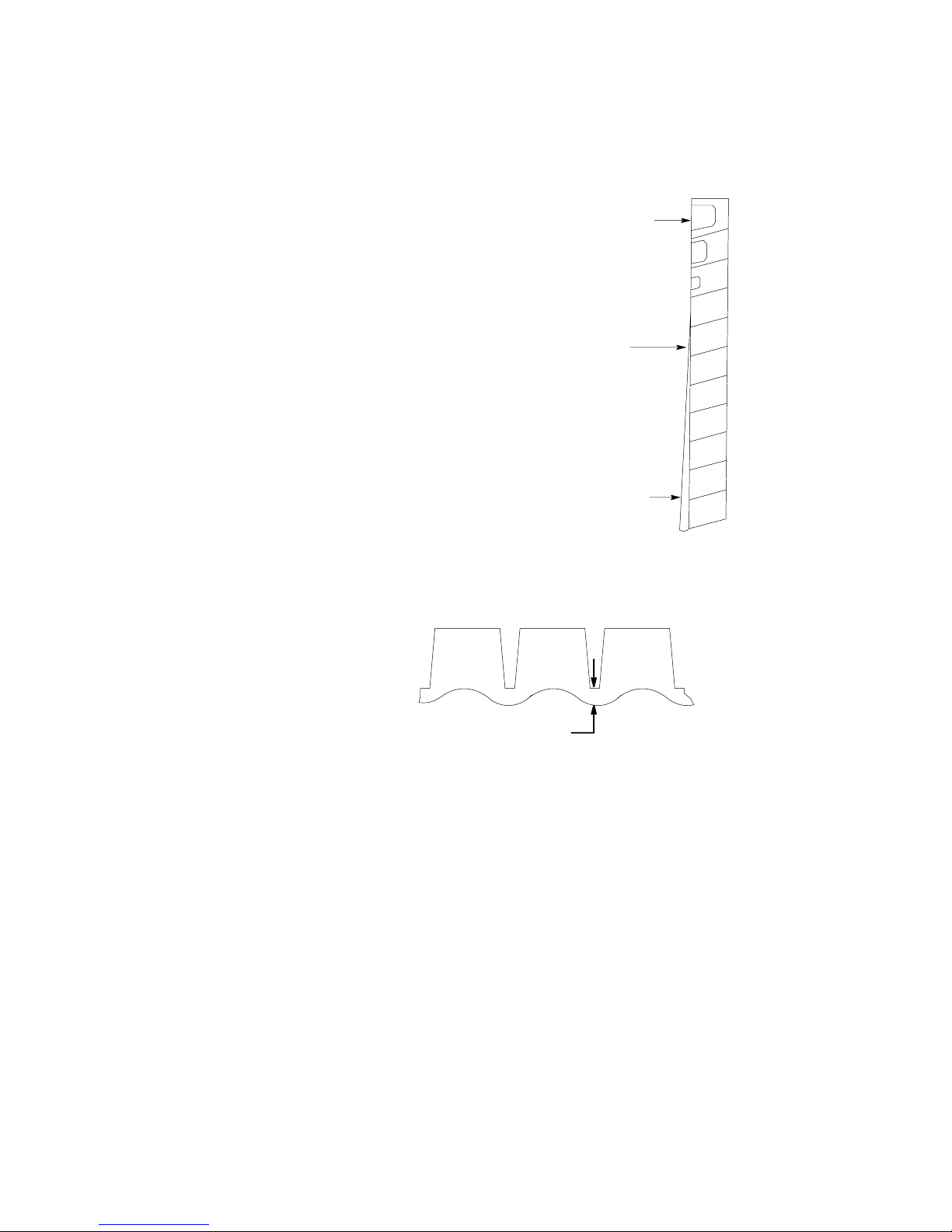
ADJUSTMENT OF ICE BRIDGE
THICKNESS
TOP ROW
.95 CM - 1.59 CM
DIMPLE
CENTER
.32 CM BRIDGE
BOTTOM 2 ROWS
.48 CM - .64 CM BRIDGE
For optimum ice production and maximum cube separation, the ice
connecting the individual cubes should be a minimum of 1/8”
(.32cm) thick at the center area of the ice waffle.
BRIDGE 1/8I (0.32 CM)
It is normal for the ice slab to be slightly thicker at the bottom and
taper off in a slight wedge pattern at the top. The top row of cubes
must have a complete pattern of ice on all four sides and the back
wall. Remember, when you operate the product with the panels off
during testing the additional heat at the top of the evaporator will
cause thinner ice at the top than when the panels are in place.
12TD 204

Should a different thickness of the bridge be desired, it will be required to adjust the ice thickness “POT”, located on the circuit
board, as follows:
1. Thinner Bridge – turn the ice thickness “pot” adjustment screw CW one full turn. Allow two cycles
before determining if additional adjustments are required.
2. Thicker Bridge – turn the ice thickness “pot” adjusting
screw CCW one full turn. Allow two cycles before
determining if additional adjustments are required.
NOTE: Never judge the thickness of the ice from the first
batch of the ice produced – the first cycle is a bal-
ance cycle. Always wait for the second cycle before
making any adjustments.
13 TD 204

14
TD 204
IAC322/IAC330
FREEZE CYCLE HARVEST CYCLE
AMBIENT
TEMP
_C
WATER
TEMP
_C
HEAD
PRESSURE
kPa
SUCTION
PRESSURE
kPa
CYCLE
TIME
Min:Sec
HEAD
PRESSURE
kPa
SUCTION
PRESSURE
kPa
CYCLE
TIME
Min:Sec
AVERAGE
ICE
WEIGHT
kg/Cycle
AVERAGE
ICE
WEIGHT
kg/day
21 10 1379 269 9:5 1034 724 1:1 1.1 147
27 21 1572 290 12:4 1103 758 0:9 1.1 118
32 21 1841 303 14:3 1262 917 0:7 1.1 109
32 27 1862 310 15.1 1248 896 0.7 1.1 100
38 21 2062 324 19:8 1372 979 0:6 1.3 91

15 TD 204
IWC322/IWC330
FREEZE CYCLE HARVEST CYCLE
AMBIENT
TEMP
_C
WATER
TEMP
_C
HEAD
PRESSURE
kPa
SUCTION
PRESSURE
kPa
CYCLE
TIME
Min:Sec
HEAD
PRESSURE
kPa
SUCTION
PRESSURE
kPa
CYCLE
TIME
Min:Sec
AVERAGE
ICE
WEIGHT
kg/Cycle
AVERAGE
ICE
WEIGHT
kg/day
21 10 2068 276 12:1 986 710 0:9 1.3 141
27 21 2068 290 15:3 1103 800 1:1 1.3 111
32 21 2068 296 16:2 1103 814 1:2 1.3 109
32 27 2089 303 16.4 1193 827 1.1 1.3 104
38 21 2068 303 16:3 1103 807 1:3 1.2 98

16
TD 204
IAC522/IAC530
FREEZE CYCLE HARVEST CYCLE
AMBIENT
TEMP
_C
WATER
TEMP
_C
HEAD
PRESSURE
kPa
SUCTION
PRESSURE
kPa
CYCLE
TIME
Min:Sec
HEAD
PRESSURE
kPa
SUCTION
PRESSURE
kPa
CYCLE
TIME
Min:Sec
AVERAGE
ICE
WEIGHT
kg/Cycle
AVERAGE
ICE
WEIGHT
kg/day
21 10 1517 262 12.5 1069 655 1:0 2.3 245
27 21 1724 290 14.6 1207 765 0.9 2.2 204
32 21 1896 283 17.4 1344 827 0.7 2.3 184
32 27 1999 310 17.9 1379 827 0.6 2.3 176
38 21 2206 317 20.9 1517 827 0.6 2.4 159

17 TD 204
IWC522/IWC530
FREEZE CYCLE HARVEST CYCLE
AMBIENT
TEMP
_C
WATER
TEMP
_C
HEAD
PRESSURE
kPa
SUCTION
PRESSURE
kPa
CYCLE
TIME
Min:Sec
HEAD
PRESSURE
kPa
SUCTION
PRESSURE
kPa
CYCLE
TIME
Min:Sec
AVERAGE
ICE
WEIGHT
kg/Cycle
AVERAGE
ICE
WEIGHT
kg/day
21 10 2227 303 11:3 1076 731 1:3 1.9 222
27 21 2255 310 13:7 1158 793 1:2 2.0 193
32 21 2248 310 13:8 1193 807 1:1 2.0 191
32 27 2261 324 15:2 1269 876 1:1 2.0 174
38 21 2255 310 13:9 1207 820 1:1 2.0 188
 Loading...