

Page 1
ColdFusion Icemaker Adapter Kit Installation Instructions
!
WARNING:
!
WARNING:
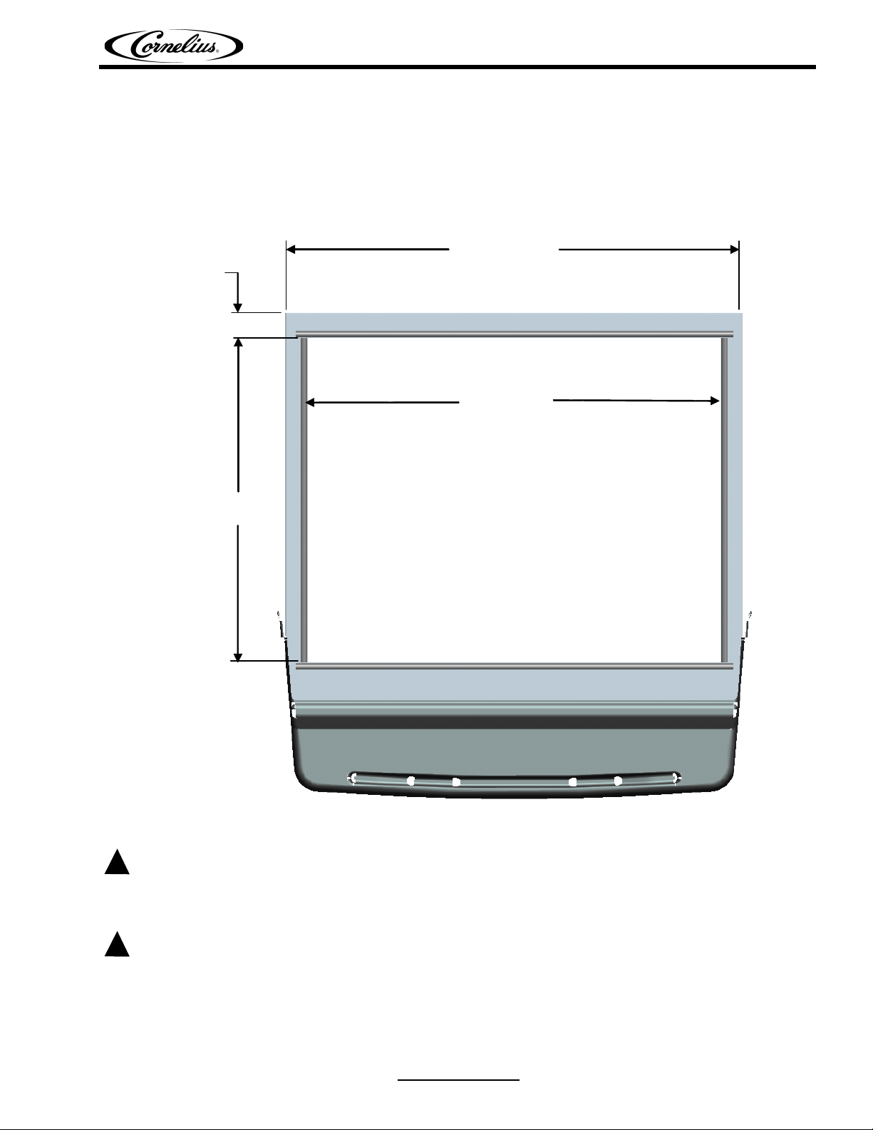
30.30”
ICE MAKER DROP ZONE
AND BIN STAT MUST FIT
WITHIN THE
27.40 X 21.50” OPENING
(BACK SIDE OF DISPENSER)
27.40”
21.50”
1.67”
INSTALLATION INSTRUCTIONS
FOR ADAPTER KIT P/N 629096828
This adapter kit is recommended for use with Cold Fusion Dispensers and Icemakers that measure 30" wide X
24.5" deep. The icemaker drop zone and bin stat must fit within the footprint shown in figure 1.
Disconnect power to the unit before installing adaptor following all lock out / tag out procedures established by the
user. Verify all of the power is off to the unit before performing any work. Failure to comply could result in serious
injury, death or damage to the equipment.
All of the attachment screws and plates must be installed as directed in this manual. Failure to comply could result in
serious Injury, Death or Damage to the equipment.
Figure 1
Release Date: October 8, 2008 www.cornelius.com Revision: B
© 2008-2010, IMI Cornelius Inc. 1 of 4 Publication Number: 629096828INS
Page 2
ColdFusion Icemaker Adapter Kit Installation Instructions
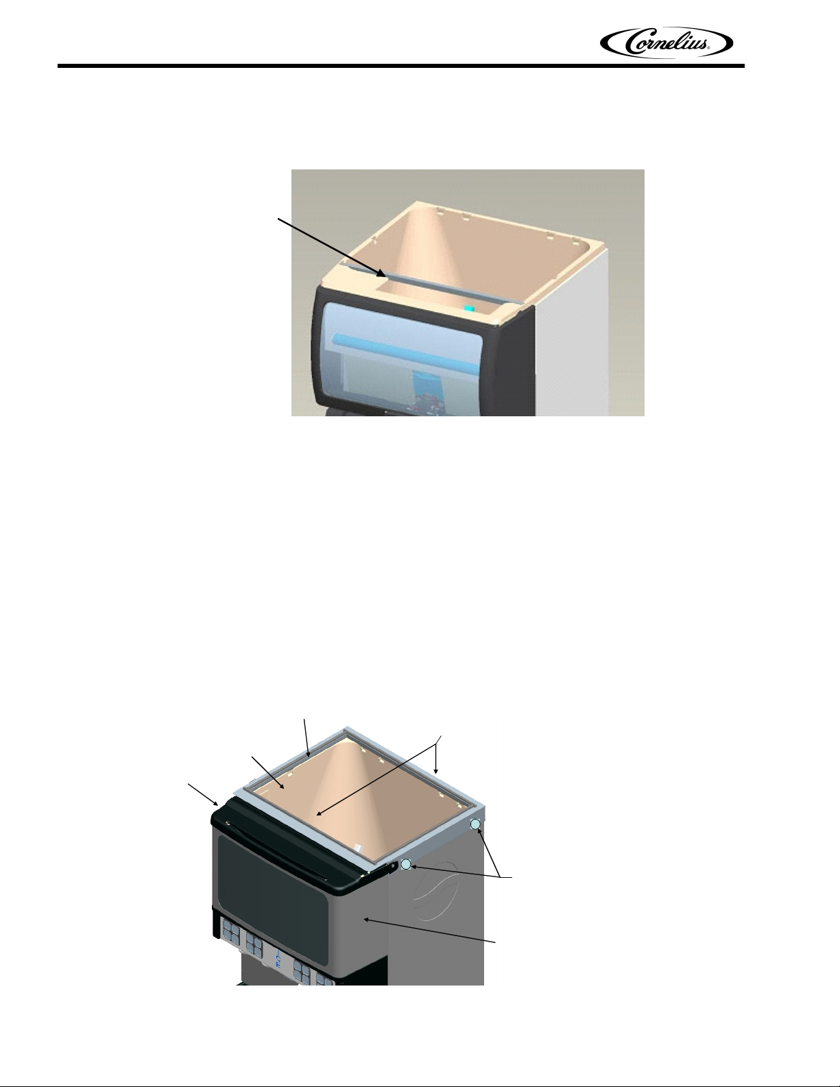
ICE MAKER
SUPPORT RAIL
HOLES FOR SECURING
KIT ARE LOCATED ON
THE SIDES (2 PER)
KIT MUST BE POSITIONED ALL THE WAY
FORWARD AND COMPRESSED DOWN
PRIOR TO DRILLING HOLES.
LID
MERCHANDISER
F
O
R
W
A
R
D
DOWN
HOPPER
SUPPORT RAILS
1. First step is to position and secure the kit to the dispensing unit. Whenever possible, this should be done
prior to lifting the dispenser onto the counter to allow sufficient access and also provide easier and faster
installation.
Figure 2
2. Place ice maker support rail into the front set of pockets in the ice bin as shown in Figure 2.
3. Position the adapter kit onto the drink dispenser so that it is pulled as far forward as it can be. The gaskets
on the inside of the kit (that rest on the hopper) must also be compressed as far down as they can go. One
design feature of the kit is to support the weight of the icemaker. The support rails (internal to the kit) resting
on the hopper provide this support. Therefore, compressing the gaskets replicate the weight of the icemaker
and should be done prior to drilling any holes, as mentioned in the next step.
4. Using the four holes in the adapter cover as templates, drill 9/64" (.140" Dia.) holes in the sides of the
dispenser (2 holes per side). USE EXTREME CAUTION NOT TO DRILL INTO ANY OTHER
COMPONENTS. Maximum drill depth from the face of the kit should not exceed 3/8" (just enough to go
through the material being drilled). Remember, the kit should be all the way forward and compressed down
before drilling the holes. Otherwise, undesirable gaps may result (lid to merchandiser) and the internal latch
feature for the lid may not function properly. After holes are drilled, secure the kit to the machine using the
screws provided (refer to Figure 3).
Publication Number: 629096828INS 2 of 4 © 2008-2010, IMI Cornelius Inc.
Figure 3
Page 3

ColdFusion Icemaker Adapter Kit Installation Instructions
DETAIL “A”
DEATIL A
5. When ready, lift the machine onto the counter.
6. Position the icemaker on top of the kit. Do not slide the icemaker into position. This may tear the gasket
material on top. Instead, lift and position the icemaker into place. The back side of the icemaker should line
up with the back of the kit. Side walls should also be centered from left to right. Connect the icemaker
according to the manufacturer’s requirements.
7. Apply a continuous bead of silicone (supplied) around the icemaker to seal it to the kit. (For reference Silicone is NSF International Listed Silastic Sealant, Dow 732 or equivalent).
8. The next step is to secure the icemaker to the kit. Use the brackets (supplied) as templates to drill four 9/64”
(.140” Dia.) holes into the adapter kit (2 per side). When drilling holes, the maximum distance from the back
of the kit is 7.50 inches (refer to Figure 4) . Failure to comply will result in damage to the sliding arm
mechanisms internal to the kit. Drill four holes of the same diameter into the icemaker (2 per side). Ensure
the location of the brackets will not damage the kit or the icemaker prior to drilling any holes. USE
EXTREME CAUTION NOT TO DRILL INTO ANY OTHER COMPONENTS. Drill depths should not go
further than the thickness of the material being drilled (just enough to go through). Secure the two brackets
using the screws provided.
Figure 4
Installation is complete. For optimal performance, Do not fill ice bin to more than 2/3 of capacity. Recommended maximum fill height is four (4) inches from the top of the bin.
© 2008-2010, IMI Cornelius Inc. 3 of 4 Publication Number: 629096828INS
Page 4

ColdFusion Icemaker Adapter Kit Installation Instructions
- COMPLETED ASSEMBLY –
COLD FUSION DISPENSER WITH ADAPTER KIT
P/N 629096828, AND 30” X 24.5” ICE MAKER
Adapter Kit Operating Instructions
1. The plastic lid of the kit slides in and out and also hinges upward. This provides access to the hopper in the
event manual ice filling is required. Simply pull out the lid and hinge upward. The lid will remain in the up
position on its own.
2. If manual filling is required, the lid must be pulled out and lifted up out of the way. Do not leave the lid down
and rest a bucket of ice on it while manual filling as this may cause damage to the lid.
Figure 5
Publication Number: 629096828INS 4 of 4 © 2008-2010, IMI Cornelius Inc.
 Loading...