

Page 1
Thermostat Reset Upgrade Kit Installation Instructions
INSTALLATION INSTRUCTIONS
FCB Pinnacle 2 Flavor Emerson Units
THERMOSTAT RESET UPGRADE KIT P/N 629088480
IMPORTANT: This procedure is intended for use by a Qualified Service Technician.
IMPORTANT: This kit is intended to be a direct replacement of the existing safety circuit. If the
unit does not have a reset box on the back, call IMI Cornelius Service at 800-238-3600.
NOTE: Open the Cornelius web site www.cornelius.com, search for 629088480INS, and print the
instructions off in color.
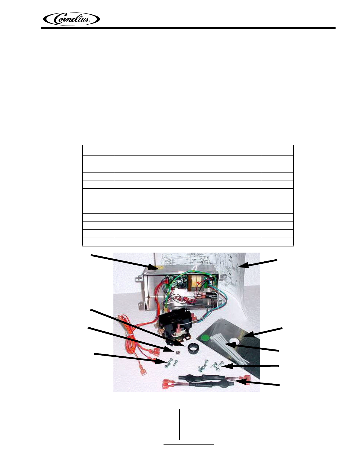
Parts List
Item Description Qty
1 Retro-Kit Enclosure Box (with wiring inside) 1
2 Hole Template 1
3 Short Thread-Cutting Screws (if needed) 6
4 Set of wire ties 1
5 Screws, 1 spare 3
6 Wiring Diagram – 620920907 1
7 7/8” Bushing (if needed) 1
8 Hex Nut 1
9 Harness, In-Rush Protection 2
10 Label, Hot Gas Error (not shown) 1
11 Brass Screws and S.S. Lock-washers (not shown) 4
Retro-Kit
Enclosure Box
Bushing
Hex Nut
Screws
Wire Diagram
Hole Template
Set of Wire Ties
Short Thread
Cutting Screws
In-Rush Protection
Harnesses
Tool List
Multi-Use Screwdriver Wire Stripper/Crimper
1/4” Nut Driver Needle Nose Pliers
Multi-meter Set of Mixed Terminals (red male and female
Release Date: June 30, 2005 www.cornelius.com Revision: C
© 2005, IMI Cornelius Inc. - 1 - Publication Number: 629088480INS
AMP fastons, fully insulated)
Page 2
Thermostat Reset Upgrade Kit Installation Instructions
Installation Instructions
1. Pull Pinnacle away from wall. DISCONNECT POWER FROM THE UNIT. Remove lower back
panel.
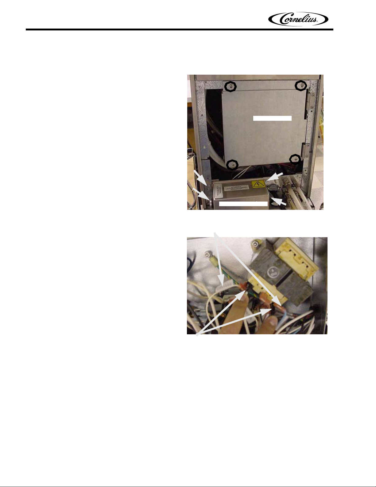
2. Remove the 4 screws holding contactor
box cover (bottom rear of unit). The box
will now pivot on hinges. Also remove the
4 screws holding the original safety circuit
box on the back of the lower frame.
Contactor Box
3. Remove leads LD1 and LD2 from
transformer 1, located in contactor box.
These are the piggybacked connections.
Remove the labeled terminals from the
piggybacks and replace in their original
positions.
Original Safety Box
Place TX1-LD1 and TX1-LD2 back on transformers.
Use same location from placement.
Remove piggybacked wires and leads from transformer.
Publication Number: 629088480INS - 2 - © 2005, IMI Cornelius Inc.
Page 3
Thermostat Reset Upgrade Kit Installation Instructions
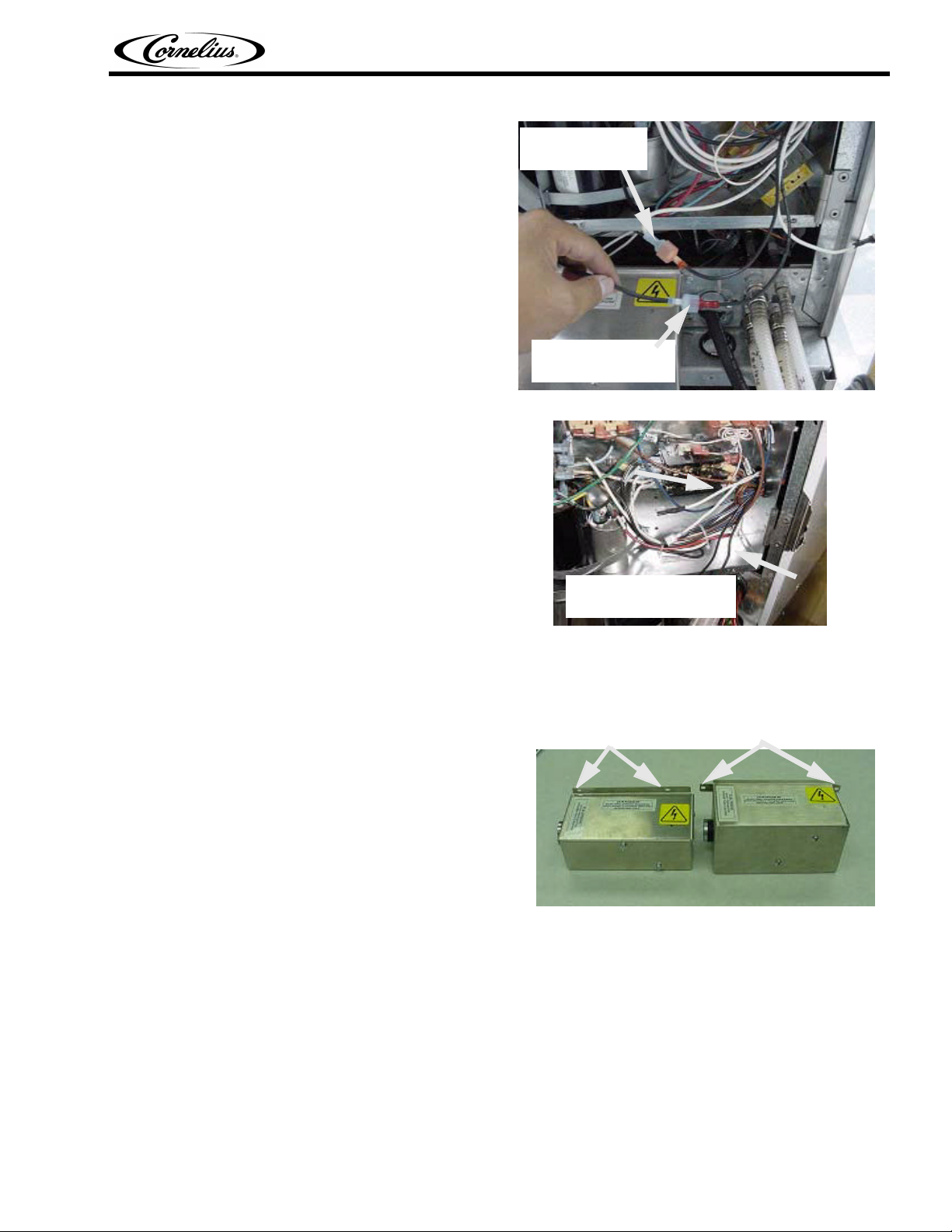
4. Remove thermostat wires from their
connections. Feed the wires out of the
contactor box. Discard the black jumper
wire.
5. Feed the white wires that originate from
the safety circuit box out of the contactor
box.
Disconnect white
contactor wire from
thermostat wire.
Disconnect black
jumper from thermostat
wire and discard.
Remove the two white wires
and black thermostat wires
from contactor box.
6. Pull out safety circuit box and remove the ground screw. Disconnect the main power and contactor
harness leads for the contactor.
7. Feed the white wires out through the hole and remove the box.
NOTE: Note the mounting hole locations on
the original box. If the mounting holes are on
Box with mounting holes on
top and bottom. Drill new.
Box with mounting holes on
sides. Use existing.
the side of the box, proceed to step 14.
If the mounting locations are on the top and
bottom, remove all wires and bushing and
proceed to the next step to drill new
mounting holes.
© 2005, IMI Cornelius Inc. - 3 - Publication Number: 629088480INS
Page 4

Thermostat Reset Upgrade Kit Installation Instructions
8. Place hole template at lower left of back of frame. The dot sticker should be at the lower left of
template. Line up edge of hole template to edge of frame, as shown, and clamp in place.
Template
Dot sticker in
lower left.
Clamp in place.
Start Holes
9. Start 4 smaller holes with the drill using the 1/8” bit through template and into frame. DO
NOT DRILL THE ENTIRE HOLE, ONLY START HOLE TO MARK LOCATION! If preferred, use a
center punch to mark hole locations.
10. Unclamp the template and place just
inside frame, as shown. The template
MUST BE between the frame and hoses to
prevent hose puncture. Be sure that large
hole in template is in position well above
the holes being drilled
Place template, as shown,
between frame and hoses.
11. Drill the two small holes near the left side. Move the template, as shown, when finished drilling
making sure it is between the frame and hoses, with the large template hole away from the right
side holes. Drill the 2 smaller holes on the right.
Place template in this
position when drilling
large hole.
12. File down any burrs on all 4 holes, carefully clean up all metal shavings.
13. Place Snap Bushing in the 7/8” hole. Feed the main power and contactor harnesses through the
hole.
Publication Number: 629088480INS - 4 - © 2005, IMI Cornelius Inc.
Page 5

Thermostat Reset Upgrade Kit Installation Instructions
Main power lead
harness.
Harness from
contactor box.
Snap bushing inserted.
14. Remove contactor from box and connect main power and contactor harnesses, as shown.
IMPORTANT – Main power MUST be on same side as flag terminals already attached to contactor
(see photo). Remount contactor in box.
Main power
harness
here.
Contactor
harness
here.
15. Feed the remaining 4 wires (2 red, 2
orange) through hole.
Remount contactor in the box by
locating this screw than turn the
contactor to locate the other screw.
Feed these wires through the hole.
© 2005, IMI Cornelius Inc. - 5 - Publication Number: 629088480INS
Page 6

Thermostat Reset Upgrade Kit Installation Instructions
16. Disconnect terminals bridging the two
thermostats (see photo). Remove wire tie,
if present.
17. Take the wires from the safety circuit and connect them to the thermostats.
IMPORTANT: Make sure that you connect the two red wires to one thermostat and the orange
wires to the other thermostat. Zip tie the bundles together.
Disconnect wires here.
Remove wire tie, if present.
Red
Power Leads
18. Change out the screws in the back of the
thermostat with the supplied brass and
stainless steel lockwashers.
NOTE: Only remove one screw at a time. Do
not remove both screws at the same time or
the thermostat can fall and be damaged.
19. Using hand tools remove one screw.
Wire tie bundles
together.
Orange
Publication Number: 629088480INS - 6 - © 2005, IMI Cornelius Inc.
Page 7

Thermostat Reset Upgrade Kit Installation Instructions
20. Place the stainless steel lock-washer over
the brass screw and thread it in (a “screw
starter” screwdriver makes this much
easier).
NOTE:
• Make sure both screws are in place and
secure.
• Do not use power tools to drive screws.
• Use caution not to overtighten the
screw.
21. Insure screw is flush and sealed against lock washer, as shown.
22. Repeat procedure for second screw.
23. Repeat steps 18-20 for all barrels.
If the existing screws do not come out or they break during this change, call IMI Cornelius Service at 800238-3600.
24. After screw replacements, insure thermostat is flush against brass retaining nut, by grasping the
body of the thermostat with your finger and gently trying to wiggle it. No movement should be
detected. If movement is detected, tighten screws and recheck.
Check
Correct
Incorrect
WARNING: If thermostat is loose, it will not correctly detect an over temperature condition. This
could allow product to overheat without being detected.
© 2005, IMI Cornelius Inc. - 7 - Publication Number: 629088480INS
Page 8

Thermostat Reset Upgrade Kit Installation Instructions
25. Set three ground wires (1 from contactor
box, 1 from main power, and 1 from safety
box) in place and tighten screw (see
photo).
26. Before connecting power check the following:
A. Verify that all connections are placed properly per the instructions.
B. Verify that all connections are firmly attached.
C. Verify that the ground connection does not touch a terminal on the contactor in the safety circuit
enclosure.
D. Verify that incoming power L1 and L2 are on the side of the contactor with the existing wires.
E. Verify that the unit power leads T1 and T2 are on the side of the contactor without the existing
wires.
27. After verifying that the unit is wired correctly, connect power to unit and verify. If the unit does not
power up and the red LED is illuminated, call IMI Cornelius Service at 800-238-3600. If the unit
powers up normally, disconnect power and complete the install.
28. Feed remaining extra wire back through
the hole.
Set ground leads
with screw and
tighten nut on
inside of frame.
Route extra
wire back into
unit.
Publication Number: 629088480INS - 8 - © 2005, IMI Cornelius Inc.
Page 9

29. Make sure all wires are in the safety circuit
box, hold box in place against the frame,
and drive 4 short thread-cutting screws
(included in kit) through safety circuit box
into frame.
30. Swing Contactor Box “closed” and place
cover over box. Drive the 4 screws that
were removed to hold cover and box in
place on unit.
Thermostat Reset Upgrade Kit Installation Instructions
31. Replace lower back panel of unit. Move
unit back into place for operation. Open
the front control box to add the in-rush
protection harnesses.
In-Rush
Protection
Harness
© 2005, IMI Cornelius Inc. - 9 - Publication Number: 629088480INS
Page 10

Thermostat Reset Upgrade Kit Installation Instructions
32. Pull the Brown wire labeled “P4” from its
location on the Emerson Inverter Board
33. Place the female terminal of the In-Rush
Protection harness on the terminal that
you just removed the brown wire from.
MAKE SURE THIS IS THE BOARD
TERMINAL LABELED “P4”.
P4 Brown Wire
P4 Board Terminal
Harness
Location for the In-Rush
Protection Harnesses
34. Mate the male terminal of the In-Rush Protection Harness with the Brown wire “P4” terminal that
you pulled from the board.
35. Position the In-Rush Protection Harness into the control box so that it does not contact the control
box or door when closed. Zip tie to the main harness as needed.
36. Repeat steps 25 - 28 on each inverter board on the unit (1 board per barrel).
37. Close front control box.
38. Attach new wiring diagram directly over
the existing one. Place Hot Gas Error
Warning label directly next to the display
panel on the front of the unit.
39. Reconnect power to the unit. Installation is complete and unit is ready for normal operation.
Publication Number: 629088480INS - 10 - © 2005, IMI Cornelius Inc.
 Loading...