

Page 1
®
SELF-CONTAINTED
FLAKED ICE MAKER
Model: Series 200, 525, 725 (R404A Refrigerant)
Service Manual
Series 200
Release Date: May 13, 2004
Publication Number: 166240010SER
Revision Date: NA
Revision: A
Visit the IMI Cornelius web site at www.cornelius.com
for all your Literature needs.
Page 2

SELF-CONTAINED FLAKED ICE MAKER
SERVICE MANUAL
The products, technical information, and instructions contained in this manual are subject
to change without notice. These instructions are not intended to cover all details or variations of the equipment, nor to provide for every possible contingency in the installation,
operation or maintenance of this equipment. This manual assumes that the person(s)
working on the equipment have been trained and are skilled in working with electrical,
plumbing, pneumatic, and mechanical equipment. It is assumed that appropriate safety
precautions are taken and that all local safety and construction requirements are being
met, in addition to the information contained in this manual.
To inquire about current revisions of this and other documentation or for assistance with
any Cornelius product contact:
www.cornelius.com
800-238-3600
Trademarks and copyrights:
Aurora, Cornelius, Decade, Hydro Boost, Sitco, Spirit, UF-1, Vanguard, Venture, Olympus,
and Vista are registered trademarks of IMI Cornelius Inc.
Optifill trademark is pending.
This document contains proprietary information and it may not be
reproduced in any way without permission from Cornelius.
Printed in U.S.A.
Copyright © 2004, All Rights Reserved, IMI Cornelius, Inc.
Page 3

TABLE OF CONTENTS
Introduction . . . . . . . . . . . . . . . . . . . . . . . . . . . . . . . . . . . . . . . . . . . . . . . . . . . . . . . . . . 1
Specifications 200 . . . . . . . . . . . . . . . . . . . . . . . . . . . . . . . . . . . . . . . . . . . . . . . . . . . . . 2
Ice Production Capacity (Approximate) . . . . . . . . . . . . . . . . . . . . . . . . . . . . . . . . . . . 2
200 . . . . . . . . . . . . . . . . . . . . . . . . . . . . . . . . . . . . . . . . . . . . . . . . . . . . . . . . . . . 3
Specifications 525 . . . . . . . . . . . . . . . . . . . . . . . . . . . . . . . . . . . . . . . . . . . . . . . . . . . . . 4
Ice Production Capacity (Approximate) . . . . . . . . . . . . . . . . . . . . . . . . . . . . . . . . . . . 4
525 . . . . . . . . . . . . . . . . . . . . . . . . . . . . . . . . . . . . . . . . . . . . . . . . . . . . . . . . . . . 5
Specifications 725 . . . . . . . . . . . . . . . . . . . . . . . . . . . . . . . . . . . . . . . . . . . . . . . . . . . . . 6
Ice Production Capacity (Approximate) . . . . . . . . . . . . . . . . . . . . . . . . . . . . . . . . . . . 6
725 . . . . . . . . . . . . . . . . . . . . . . . . . . . . . . . . . . . . . . . . . . . . . . . . . . . . . . . . . . . 6
Electrical Circuit . . . . . . . . . . . . . . . . . . . . . . . . . . . . . . . . . . . . . . . . . . . . . . . . . . . . . . 7
Circuit Description . . . . . . . . . . . . . . . . . . . . . . . . . . . . . . . . . . . . . . . . . . . . . . . . . . . 7
On-Off Switch/Circuit Breaker . . . . . . . . . . . . . . . . . . . . . . . . . . . . . . . . . . . . . . . 7
Bin Thermostat . . . . . . . . . . . . . . . . . . . . . . . . . . . . . . . . . . . . . . . . . . . . . . . . . . 7
High Pressure Control . . . . . . . . . . . . . . . . . . . . . . . . . . . . . . . . . . . . . . . . . . . . . 7
Gearmotor Start Relay . . . . . . . . . . . . . . . . . . . . . . . . . . . . . . . . . . . . . . . . . . . . 7
Power Relay/Contactor . . . . . . . . . . . . . . . . . . . . . . . . . . . . . . . . . . . . . . . . . . . . 7
Fan Cycling Switch . . . . . . . . . . . . . . . . . . . . . . . . . . . . . . . . . . . . . . . . . . . . . . . 7
Delay Thermostat . . . . . . . . . . . . . . . . . . . . . . . . . . . . . . . . . . . . . . . . . . . . . . . . 7
Compressor Start Relay . . . . . . . . . . . . . . . . . . . . . . . . . . . . . . . . . . . . . . . . . . . 7
Potential Relays . . . . . . . . . . . . . . . . . . . . . . . . . . . . . . . . . . . . . . . . . . . . . . . . . 8
Capacitors - General . . . . . . . . . . . . . . . . . . . . . . . . . . . . . . . . . . . . . . . . . . . . . . 8
Maintenance . . . . . . . . . . . . . . . . . . . . . . . . . . . . . . . . . . . . . . . . . . . . . . . . . . . . . . . . . 9
Sanitizing and Cleaning Procedure . . . . . . . . . . . . . . . . . . . . . . . . . . . . . . . . . . . . . . 9
Water Treatment . . . . . . . . . . . . . . . . . . . . . . . . . . . . . . . . . . . . . . . . . . . . . . . . . . . 10
Winter Storage . . . . . . . . . . . . . . . . . . . . . . . . . . . . . . . . . . . . . . . . . . . . . . . . . . . . 10
Cleaning the Condenser (Air Cooled) . . . . . . . . . . . . . . . . . . . . . . . . . . . . . . . . . . . 10
Troubleshooting . . . . . . . . . . . . . . . . . . . . . . . . . . . . . . . . . . . . . . . . . . . . . . . . . . . . . 15
Page 4

Page 5

Self-Contained Flaked Ice Maker Service Manual
INTRODUCTION
We have strived to produce a quality product. The design has been kept simple thus insuring trouble-free
operation.
This manual has been prepared to assist servicemen and users with information concerning installation,
construction and maintenance of the ice making equipment. The problems of the serviceman and user
have been given special attention in the development and engineering of our ice makers.
If you encounter a problem which is not covered in this manual, please feel free to write or call. We will be
happy to assist you in any way we can.
When writing, please state the model
and serial number of the machine.
© 2004, IMI Cornelius Inc. - 1 - Publication Number: 166240010SER
Page 6
Self-Contained Flaked Ice Maker Service Manual
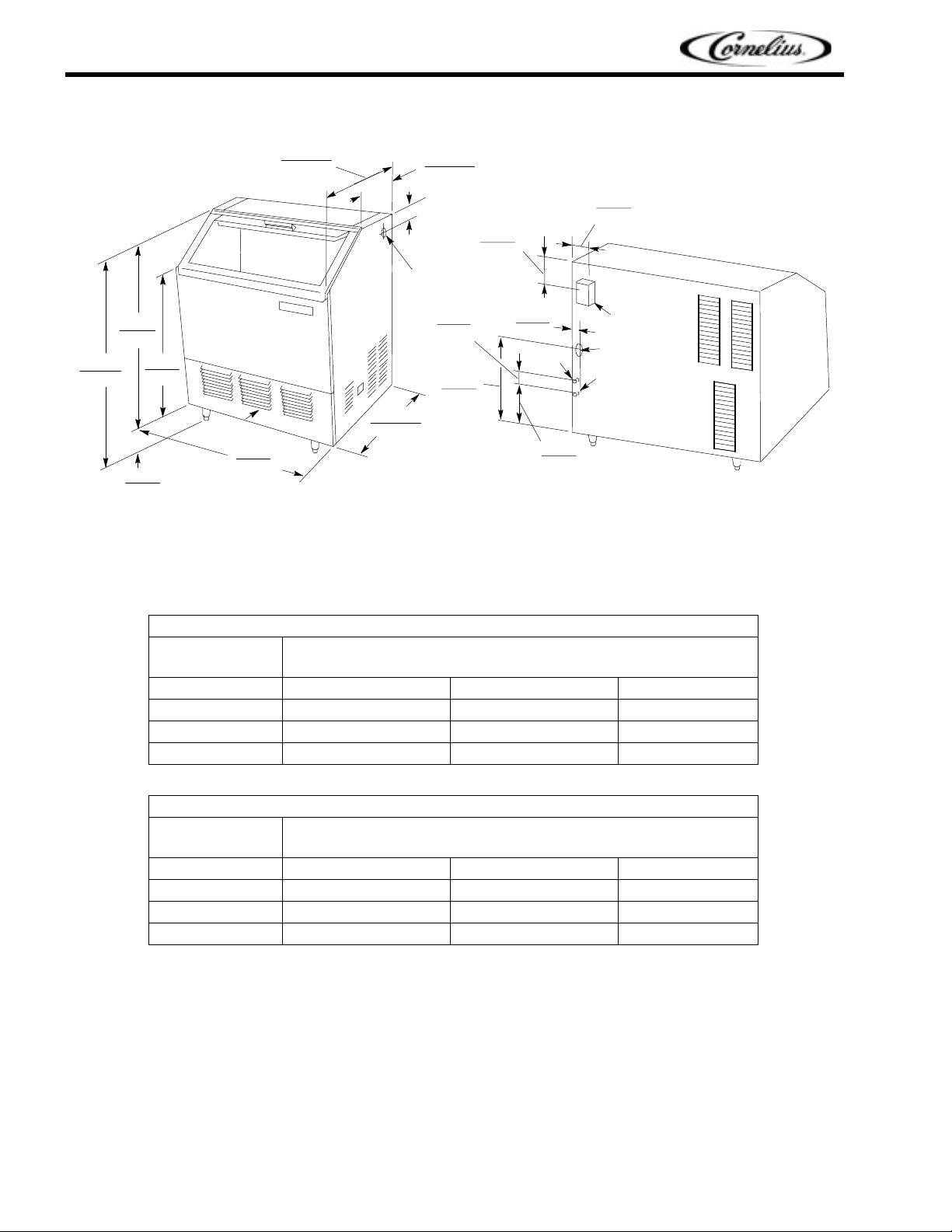
SPECIFICATIONS 200
40-IN.
102-C M
34-IN.
86-C M
6-IN.
15-C M
26-IN.
66-C M
AIR
FLOW
26 1/2-IN.
67-C M
24 7/8-IN.
25-IN.
64-C M
A- 1/4 W ATE R INLE T S
(S . A.E . MALE FLAR E )
B- 5/8 O.D. TUBE (DRAIN)
C- 1/2 O.D. TUBE (DRAIN)
13 1/2-IN.
34-C M
7-IN.
18-C M
ON-OFF
SWITCH
5-IN.
13-C M
19-IN.
48-C M
63-C M
FIGURE 1. 200 SERIES SPECIFICATIONS
ICE PRODUCTION CAPACITY (APPROXIMATE)
3/4-IN.
2-C M
B
7-IN.
18-C M
4-IN.
10-C M
REAR VIEW
OF CABINET
ELECTRICAL
BOX AREA
A
C
AIR
TEMPERATURE
50°F/10°C
70
°F/21°C
°F/27°C
90
AIR
TEMPERATURE
50
°F/10°C
70
°F/21°C
°F/27°C
90
AF–200–P(S)–SCR PRODUCTION CHART
WATER TEMPERATURE
°F/10°C70°F/21°C80°F/27°C
50
219 lbs/99 kgs 188 lbs/85 kgs 175 lbs/79 kgs
208 lbs/95 kgs 174 lbs/79 kgs 166 lbs/75 kgs
161 lbs/35 kgs 130 lbs/59 kgs 117 lbs/53 kgs
AF–200–P–SC50R PRODUCTION CHART
WATER TEMPERATURE
°F/10°C70°F/21°C80°F/27°C
50
234 lbs/106 kgs 206 lbs/94 kgs 197 lbs/90 kgs
213 lbs/97 kgs 190 lbs/86 kgs 180 lbs/82 kgs
183 lbs/83 kgs 164 lbs/75 kgs 156 lbs/71 kgs
Publication Number: 166240010SER - 2 - © 2004, IMI Cornelius Inc.
Page 7

200
Self-Contained Flaked Ice Maker Service Manual
Compressor Model Copeland JS25CIE–IAA–203 (115V 60HZ)
Copeland AS13CIE–1AZ–908 (220V 50HZ)
Condenser Air Cooled
Refrigerant Charge 8 oz. R–404a (115V 60HZ)
7 oz. R–404a (220V 50HZ)
Refrigerant Control (115V 60HZ) Automatic Expansion Valve (28–PSI)
Refrigerant Control (220V 50HZ) Automatic Expansion Valve (31–PSI)
Inlet Water Supply 1/4” SAE male flare
Voltage 115V 60HZ or 220V 50HZ
Gearmotor Electrical Rating 1/8 hp
Gearmotor Amp. Rating 2 amps (115V 60 HZ)
1 amp (220V 50HZ)
Total Amp. Draw 11.0 Amps (115V 60HZ)
4.0 Amps (220V 50HZ)
Maximum Fuse Size 15 Amp (115V 60HZ)
15 Amp (220V 50HZ)
© 2004, IMI Cornelius Inc. - 3 - Publication Number: 166240010SER
Page 8

Self-Contained Flaked Ice Maker Service Manual
SPECIFICATIONS 525
34-IN.
86-C M
40-IN.
102-C M
MIN.
15-C M
26-IN.
66-C M
AIR IN
38 3/4-IN.
97-C M
6-IN.
MIN.
A- 3/8 W ATE R INL E T (S . A.E . MALE F LAR E )
B- 1/2 O.D. TUBE (CONDENSATE DRAIN)
C- 3/4 N.P.T. BIN DR AIN
D- CONDENSER WATER IN (W/C ONLY)
E- CONDENSER WATER OUT (W/C ONLY)
26 1/2-IN.
67-C M
24 3/4-IN.
63-C M
14-IN.
36-C M
13 1/2-IN.
2-IN.
5-C M
21/2-IN.
6-C M
ON-OFF
SWITCH
34-C M
ELECTRICAL
BOX AREA
55/8-IN.
19 1/2-IN.
50-C M
45/8-IN.
31/2-IN.
9-C M
14-C M
12-C M
33/8-IN.
9-C M
FIGURE 2. 525 SERIES SPECIFICATIONS
31/2-IN.
9-C M
REAR VIEW
D
E
OF CABINET
35/8-IN.
9-C M
C
5/8-IN.
2-C M
A
B
33/4-IN.
10-C M
26 3/8-IN.
67-C M
ICE PRODUCTION CAPACITY (APPROXIMATE)
AF–525–P(S)–SCR PRODUCTION CHART
AIR
TEMPERATURE
50
°F/10°C
70°F/21°C
°F/27°C
90
AIR
TEMPERATURE
50
°F/10°C
°F/21°C
70
90
°F/27°C
°F/10°C70°F/21°C80°F/27°C
50
654 lbs/297 kgs 588 lbs/267 kgs 552 lbs/251 kgs
639 lbs/290 kgs 563 lbs/256 kgs 521 lbs/237 kgs
562 lbs/255 kgs 479 lbs/218 kgs 448 lbs/204 kgs
AF–525–P–SC50R PRODUCTION CHART
50
°F/10°C70°F/21°C80°F/27°C
629 lbs/286 kgs 528 lbs/240 kgs 494 lbs/225 kgs
621 lbs/282 kgs 525 lbs/239 kgs 489 lbs/222 kgs
493 lbs/224 kgs 414 lbs/188 kgs 387 lbs/176 kgs
WATER TEMPERATURE
WATER TEMPERATURE
Publication Number: 166240010SER - 4 - © 2004, IMI Cornelius Inc.
Page 9

525
Self-Contained Flaked Ice Maker Service Manual
Compressor Model Copeland RS43CIE–IAA–214 (115V 60HZ)
Copeland RS43CIE–IAZ–214 (220V 50HZ)
Condenser Air Cooled
Refrigerant Charge 17 oz. R-404a
Refrigerant Control Automatic Expansion Valve (34–PSI)
Inlet Water Supply 3/8” SAE Male Flare
Voltage 115V 60HZ or 220V 50HZ
Total Amp Draw 15.5 Amps (115V 60HZ)
6.0 Amps (220V 50HZ)
Gearmotor Amp Draw 2 Amps (115V 60HZ)
1 Amp (220V 50HZ)
Gearmotor Electrical Rating 1/8 hp
Maximum Fuse Size 20 Amp (115V 60HZ)
15 Amp (220V 50HZ)
© 2004, IMI Cornelius Inc. - 5 - Publication Number: 166240010SER
Page 10

Self-Contained Flaked Ice Maker Service Manual
SPECIFICATIONS 725
86-C M
40-IN.
102-C M
MIN.
34-IN.
6-IN.
15-C M
26-IN.
66-C M
48-IN.
122-C M
AIR IN
30-IN.
76-C M
A- 3/8 WATER INLET (S.A.E.MALE FLARE)
B- 1/2 O.D. TUB E (CO NDE NS ATE DR AIN)
C- 3/4 N.P.T. BIN DR AIN
D- CONDENSER WATER IN (W/C ONLY)
E- CONDENSER WATER OUT (W/C ONLY)
SWITCH
28 3/8-IN.
72-C M
16 3/8-IN.
42-C M
17 1/8-IN.
43-C M
2-IN.
5-C M
21/2-IN.
6-C M
ON-OFF
ELECTRICAL
BOX AREA
19 1/2-IN.
50-C M
FIGURE 3. 725 SERIES SPECIFICATIONS
23/4-IN.
7-C M
55/8-IN.
14-C M
41/2-IN.
11- C M
31/4-IN.
8-C M
B
23/8-IN.
6-C M
5/8-IN.
2-C M
A
5 1/32-IN.
13-C M
32 1/16-IN.
81-C M
D
E
REAR VIEW
OF CABINET
C
4-IN.
10-C M
ICE PRODUCTION CAPACITY (APPROXIMATE)
AF–725–P–SCR PRODUCTION CHART
725
AIR
TEMPERATURE
50
°F/10°C70°F/21°C80°F/27°C
50
°F/10°C
70°F/21°C
°F/27°C
90
654 lbs/297 kgs 588 lbs/267 kgs 552 lbs/251 kgs
639 lbs/290 kgs 563 lbs/256 kgs 521 lbs/237 kgs
562 lbs/255 kgs 479 lbs/218 kgs 448 lbs/204 kgs
Compressor Model Copeland RS43CIE-IAA-214
Condenser Air Cooled
Refrigerant Charge 17 oz. R-404a
Refrigerant Control Automatic Expansion Valve (34–PSI)
Inlet Water Supply 3/8” SAE Male Flare
Voltage 115V 60HZ
Total Amp Draw 15.5 Amps
Gearmotor Amp Draw 2 Amps
Gearmotor Electrical Rating 1/8 hp
WATER TEMPERATURE
Maximum Fuse Size 20 Amp
Publication Number: 166240010SER - 6 - © 2004, IMI Cornelius Inc.
Page 11

ELECTRICAL CIRCUIT
CIRCUIT DESCRIPTION
As the manual on-off circuit breaker switch is pushed to ”on”, an electrical circuit is completed to the
gearmotor via the circuit breaker gearmotor overload, power relay/contactor, gearmotor delay thermostat
and the bin thermostat. After the previous circuit has been completed the condenser fan motor will start
as will the compressor (via the high pressure control, the compressor starting relay and low ambient
control).
On-Off Switch/Circuit Breaker
This switch interrupts power to the entire unit. The switch has a circuit breaker incorporated into its’
design. This circuit breaker will trip out in the event the gearmotor draws to high of amps. In such an
event the power is interrupted to the unit. To reset the circuit breaker and reestablish power to the unit,
push the switch to the “off” position and then back to the “on” position.
Bin Thermostat
This is electrically in ”series” with the ice making system. When the bin is full, the contact opens,
terminating power to the machine.
High Pressure Control
Switch contact will open at 450 PSI for R404a breaking the circuit to the compressor. This control is
manually re-settable.
Self-Contained Flaked Ice Maker Service Manual
Gearmotor Start Relay
This is a current type relay which means as the gearmotor run winding comes ”on” the line, the current
draw initially is relatively heavy through the relay coil (coil is in series with run winding). It then acts like a
normal relay and the N.O. start contact ”makes”, completing a circuit through the start capacitor to the
start winding. As the gearmotor picks up speed, the amp draw through the relay coil drops off allowing
the armature to return to its normal position (start contact ”opens”). This action removes the start winding
from the circuit.
Power Relay/Contactor
This relay controls the compressor power only.
Fan Cycling Switch
The function of this switch is to maintain condensing pressures at a satisfactory level during-low ambient
conditions. The switch breaks the circuit to the condenser fan motor at 205 PSI and makes the circuit at
275 PSI.
Delay Thermostat
This thermostat keeps the gearmotor running until the suction line temperature reaches 45° after the full
bin switch terminates power to the power relay.
Compressor Start Relay
This is a current type relay and contains a N.O. contact which is connected in series with the start
winding of the compressor. The relay coil is electrically in series with the run winding. When power is
applied, the compressor draws high current which sets up a magnetic field in the magnet coil which
causes the relay to operate, closing the relay contact. As the compressor approaches operating speed,
the current flowing through the coil decreases, permitting the relay contact to open, thereby opening the
starting circuit.
© 2004, IMI Cornelius Inc. - 7 - Publication Number: 166240010SER
Page 12

Self-Contained Flaked Ice Maker Service Manual
Potential Relays
The potential relay is used as a compressor starting relay, The contact in the potential relay is N.C. The
magnet coil is connected across (parallel) the start winding and is affected by induced voltage, generated
by the start winding. As the compressor comes up to design speed, the voltage across the relay coil
increases and at running speed is sometimes as much as 2 1/2 times the supply voltage. This voltage
sets up a magnetic field which causes the relay to operate. The starting relay is calibrated to remove the
start capacitor (open the starting circuit) at approximately 85% of the motor design speed.
NOTE: BOTH TYPES OF RELAYS ARE DESIGNED TO OPERATE WITHIN VERY NARROW LIMITS
OF VOLTAGE AND CURRENT DICTATED BY MOTOR DESIGN, THEREFORE, WHEN MAKING A
REPLACEMENT OF A RELAY ALWAYS PROVIDE AN EXACT REPLACEMENT, RECOMMENDED
BY THE COMPRESSOR MANUFACTURER.
Capacitors - General
An electrical capacitor is a device which stores up electrical energy. Capacitors are used with single
phase motors to provide starting torque and improve running characteristics; by feeding this energy to
the start winding in step with the run winding.
Any capacitor has three (3) essential parts, two (2) of which are usually foil plates separated and
insulated by the third part called the dielectric.
Two general types of capacitors are used with electric motors. The electrolytic starting capacitor usually
uses a very thin film of oxide on the metallic plate as the dielectric. The running capacitor usually is of the
liquid filled type.
Publication Number: 166240010SER - 8 - © 2004, IMI Cornelius Inc.
Page 13

Self-Contained Flaked Ice Maker Service Manual
MAINTENANCE
IMPORTANT: THE FOLLOWING MAINTENANCE SHOULD BE PERFORMED AT LEAST EVERY SIX
MONTHS ON FLAKED ICE MACHINES.
1. Check power supply with machine running for proper voltage.
2. Check water level in the float tank reservoir. Water level should be maintained at the top of the
evaporator. Adjust if necessary. (See illustration and adjustment procedure)
3. Clean the air-cooled condenser coil with a stiff brush or vacuum cleaner (See procedure).
CAUTION: Condenser cooling fins are sharp, use care when cleaning.
4. Clean the ice storage bin and flush the bin drain at least once a month.
5. If a water conditioner is installed in the inlet water line, change, replace, or clean the filter, strainer
or cartridge as required.
6. If heavy mineral deposits on the auger and evaporator shell are encountered due to bad local water
conditions, follow sanitizing and cleaning procedure.
7. Loosen hold-down cam locks and remove gearmotor assembly.
8. Check thrust washer; replace if noticeably worn.
9. Lift out auger and examine for wear. The corkscrew auger guide bushing pressed into the drive
block should be checked for wear. Replace if loose or if worn flat with auger drive block. If the Helix
auger on the corkscrew auger round bar becomes flat on the inside more than 1/8 of an inch over a
length of two inches or more it should be replaced.
NOTE: HELIX AUGERS DO HAVE MACHINED FLAT RELIEF SURFACES. DON’T CONFUSE THEM
WITH WORN FLAT AREAS.
Check the insert in the bottom ring of the Helix auger and replace if excessively worn.
10. Check shell vertical strips for wear. Replace the shell if excessive wear is shown.
11. Check O-Ring, replace if worn or cut.
12. Re-assemble, steps 7 through 11.
CAUTION: In re-assembling the auger gearmotor, the hold down clamps must be tight and secure.
In re-installing the evaporator shell, be absolutely sure that the “o” ring is not pinched off as this
would cause a water leak around the base of the evaporator. Lubricate the “o” ring with food grade
lubricant before re-assembling shell.
13. Check for alignment of ice chute. Make sure chute gasket is not blocking path of ice flow.
14. Check bin thermostat operation. In the mid-range position the bin thermostat will open at 42° and
has a 6° differential.
SANITIZING AND CLEANING PROCEDURE
1. Turn unit off at switch in upper rear right side panel.
2. Turn water off and remove water hose from bottom of float chamber inside of ice bin and allow to
drain from the evaporator via the hose end; or
3. Remove float chamber cover and while holding float up to prevent more water from entering the
float chamber, remove water hose from float chamber and proceed to drain the float chamber and
evaporator.
4. With water still off, restore water hose to float chamber and add 1/2 oz. of ”sanitizer” (see note
below). Turn water on.
5. Remove the bin door, float chamber cover, ice chute trim cover, two thumb screws and chute trim
gasket.
6. Using soap, hot water, and a non-metallic bristle brush or plastic scouring pad, scrub the parts
removed in step 4 as well as the interior of the ice bin, ice chute, thermowell, door tracks, ice bin
top, and around bin opening.
© 2004, IMI Cornelius Inc. - 9 - Publication Number: 166240010SER
Page 14

Self-Contained Flaked Ice Maker Service Manual
NOTE: Use care when cleaning around thermowell sensing tube; the small capillary is easily
broken. Rinse all parts in clean water.
7. In a 5 gallon bucket, mix a sanitizing solution of 1/2 oz. of sanitizer to 1 gallon of warm water (100°
to 120° F).
8. Place all small, loose parts into the sanitizing solution and allow them to soak for 10 minutes.
9. Using a clean cloth and the sanitizing solution, wipe down the interior of the ice chute, thermowell
door tracks, ice bin top, and around bin opening. Allow to air dry.
10. Reassemble the float chamber cover, ice chute gasket and cover, and bin door.
11. Turn unit switch on and allow machine to make ice for at least 1/2 hour then discard all of the ice.
DO NOT ALLOW ICE WITH SANITIZER IN IT TO BE USED.
NOTE: APPROVED SANITIZER: Household bleach such as Hi-Lex or Clorox.
WATER TREATMENT
During the freezing process, the impurities in the water have a tendency to be rejected.
However, the more dissolved solids in the water, the more troublesome the freezing operation will be.
Bicarbonates in the water are the most troublesome of the impurities. These impurities will cause scaling
on the evaporator, clogging of the float valve mechanism and other parts in the water system. If the
concentration of impurities is high, wet mushy ice may be the result.
Parts of the ice maker, that are in contact with the water or ice, may corrode if the water is high in acidity.
In some areas, water may have to be treated in order to overcome some of the problems that arise
because of the mineral content.
IMI Cornelius has water filter/treatment systems available to control impurities found in your water supply.
Contact your local dealer for more information.
WINTER STORAGE
If the unit is to be stored in an area where the temperature will drop below freezing, it is most important
that all water lines be drained to prevent them from freezing and possible rupture.
To blow out the water line, disconnect the water supply at the cabinet inlet and use air pressure to force
the water into the water reservoir pan. This can then be removed from the water pan.
WATER COOLED CONDENSER
compressed air hose. Start machine. As head pressure reaches the appropriate level opening the water
regulating valve, the compressed air will force the water out. Do not let the machine operate longer than
necessary.
- To remove water from condenser unhook water supply and attach
CLEANING THE CONDENSER (AIR COOLED)
In order to produce at full capacity, the refrigeration condenser must be kept clean. The frequency of
cleaning will be determined by surrounding condition. A good maintenance plan calls for an inspection at
least every two months.
Remove the unit compartment grill at the front. With a vacuum cleaner, remove all accumulated dust and
lint that has adhered to the finned condenser.
CAUTION: Condenser cooling fins are sharp. Use care when cleaning.
Publication Number: 166240010SER - 10 - © 2004, IMI Cornelius Inc.
Page 15

Self-Contained Flaked Ice Maker Service Manual
BK
YL
BK
GR
BK
BL
BIN
THERMOSTAT
BL
MANUAL RESET
HIGH PR ESS CNTRL
C.O. 450 PSIG
BL
BK
CONTACTOR
WH
BK
WH
ON--OFF SWITCH
CIRCUIT BREAKER
RATED 2.0 AMPS
BK
BK
GEAR MOTOR
START RELAY
BK
COMPRESSOR
OVERLOAD
BK
3
2
C.O. 205 C .I. 275
1
GEAR MOTOR
START CAPACITOR
64-- 77 MFD 165 VAC
4
RD
FAN SW IT C H
BL
RD
COMPRESSOR
R
C
S
WH
GEAR
MOTOR
M
WH
FAN MOTOR
BK
1
RD
YL
COMPRESSOR
START RELAY
2
5
3
YL
M
WH
BK
BK
BK
COMPRESSOR
START CAPACITOR
145-- 174 MFD 220 VAC
WH
115 V O LTS 60 H z
AF--200--P-- SC --R
Part No. 161909061
Artwork 50922
FIGURE 4. WIRING DIAGRAM AF- 200-P–SC–R 115 VOLTS 60 HZ
© 2004, IMI Cornelius Inc. - 11 - Publication Number: 166240010SER
Page 16

Self-Contained Flaked Ice Maker Service Manual
LB
LB
RD
BR
GN/Y
BL
BL
HIGH PRESS CNTRL
BL
BK
BR
BL
CONTACTOR
BIN
THERMOSTAT
MANUAL RESET
C.O. 450 PSIG
RD
RD
BK
ON--OFF SWITCH
CIRCUIT BREAKER
RATED 1.5 AMPS
BL
BL
GEAR MOTOR
START RELAY
BK
COMPRESSOR
OVERLOAD
BK
RD
GEAR MOTOR
START CAPACITOR
3
220/250 VAC
4
2
RD
FAN SW IT C H
C.O. 205 C.I. 275
1
BK
RD
BL
21-- 25 MFD
RD
COMPRESSOR
R
C
S
GN/Y
BL
GEAR
MOTOR
M
GN/Y
FAN MO TO R
BK
M
RD
YL
COMPRESSOR
START RELAY
2
1S
YL
RD
M
GN/Y
RD
BK
BK
COMPRESSOR
START CAPACITOR
50-- 60 MFD 330 VAC
RD
BK
AF--200--P--SC--50--R
220 VOLTS 50 Hz
Part No. 161909064
Artwork 50929
FIGURE 5. WIRING DIAGRAM AF–200–P–SC–50–R 220 VOLTS 50 HZ
Publication Number: 166240010SER - 12 - © 2004, IMI Cornelius Inc.
Page 17

Self-Contained Flaked Ice Maker Service Manual
BK
YL
BLBL
GW
BL
BIN
THERMOSTAT
RD
RD
BL
CONTROL
HIGH PR ESSURE
C.O. 450 PSI
BL
CONTACTOR
BK
WH
BL
DELAY
THERMOSTAT
RD
BL
BK
ON--OFF SWITCH
CIRCUIT BREAKER
RATED 2.0 AMPS
BK
BK
GEAR MOTOR
START RELAY
C.I. 275 C.O.205
BK
COMPRESSOR
OVERLOAD
BK
POTENTIAL
START RELAY
3
4
2
FAN SW IT C H
1
BL
GEAR MOTOR
START
CAPACITOR
RD
BK
WIRE N UT
COMPRESSOR
R
C
S
YL
5
1
RD
WH
MOTOR
RD
2
GEAR
M
BK
CONDENSOR FAN
YL
BL
M
OR
COMPRESSOR
START
CAPACITOR
243-- 292 MFD
115 VA C
YL
WH
BK
WH
A F 5 2 5 -- S C -- R
A F 7 2 5 -- S C -- R
115 V O LTS 60 H z
Part No. 161909062
Artwork 50923
Rev. B
FIGURE 6. WIRING DIAGRAM AF525-SC–R AND AF725–SC–R 115 VOLTS 60 HZ
© 2004, IMI Cornelius Inc. - 13 - Publication Number: 166240010SER
Page 18

Self-Contained Flaked Ice Maker Service Manual
ON--OFF SWITCH
GW
YL
RD
BIN
THERMOSTAT
LB
BR
CIRCUIT BREAKER
RATED 1.5 AMPS
RD
BK
BL
DELAY
THERMOSTAT
RD
GEAR MOTOR
START RELAY
BK
2
BK
YL
BL
BL
3
4
GEAR MOTOR
START
CAPACITOR
RD
RD
GEAR
MOTOR
M
GW
YL
YL
BL
RD
BK
BL
AF/WF --525PSC--50--R
Part No. 161909063
Artwork 50925
Rev. A
CONTROL
HIGH PRESSURE
CONTACTOR
RD
BK
BK
FAN SW IT C H
COMPRESSOR
OVERLOAD
RD
RD
FAN MOTOR
BK
1
WIRE N UT
COMPRESSOR
R
C
S
GW
COMPRESSOR
START RELAY
RD
YL
M
GW
BL
S
BK
COMPRESSOR
START CAPACITOR
43-- 52 MFD 330 V
L
M
RD
220 VOLTS 50 Hz
FIGURE 7. WIRING DIAGRAM AF/WF–525PSC–50–R 220 VOLTS 50 HZ
Publication Number: 166240010SER - 14 - © 2004, IMI Cornelius Inc.
Page 19

Self-Contained Flaked Ice Maker Service Manual
TROUBLESHOOTING
Trouble Probable Cause Remedy
Unit will not run A. On-off switch in ”off” position. A. Turn switch to ”on”.
B. Defective on-off switch. B. Check and replace.
Compressor cycles
intermittently.
C. Blown fuse. C. Replace fuse and check for
D. Thermostat set too warm for
ambient.
E. Power relay contacts corroded. E. Check and clean.
F. Defective thermostat. F. Check and replace.
G. Loose electrical connection. G. Check wiring.
H. Gearmotor overload protector
has cut off machine.
A. Low voltage A. Check line voltage
B. Dirty condenser B. Clean condenser
C. Air circulation restricted C. Remove restriction
D. Defective condenser fan motor D. Check and replace
E. Defective relay, overload
protector or starting capacitor.
F. Loose electrical connection F. Check wiring
cause of blown fuse.
D. Adjust colder.
H. Turn switch to off then to on.
E. Check and replace
Making wet ice. A. Surrounding air temperature
*NOTE: Special care must be used with R404a (HP62) charged systems using (POE) Polyolester oil.
The refrigeration system must not be open longer than 15 min., and the appropriate drier must be
used due to the moisture absorption properties of the POE oil.
Unit runs but makes no
ice.
too high
B. High water level in float
reservoir
C. Dirty condenser C. Clean condenser
D. Faulty compressor D. Check and replace*
E. Refrigerant leak E. Check and repair
F. ”O” ring leaking at bottom of
evaporator shell
A. Leak in refrigerant system A. Check and repair
B. Moisture in system B. Check, dehydrate and add
C. No water C. Check water supply
A. Correct or move unit
B. Lower water level
F. Check and replace
drier to system
© 2004, IMI Cornelius Inc. - 15 - Publication Number: 166240010SER
Page 20

Self-Contained Flaked Ice Maker Service Manual
D. ”O” ring leaking at bottom of
D. Check and replace ”O” ring
evaporator shell
E. Compressor not running E. Check and replace ”O” ring
Water leaks. A. Worn or bad float valve A. Check and replace
B. Float and arm assembly stuck B. Check and replace
C. ”O” ring leaking at bottom of
C. Check and replace
evaporator shell
D. Storage bin drain and tubing D. Check and repair
Excessive noise or
chattering.
A. Mineral or scale deposits on
inside of evaporator shell
A. Remove and clean inside
surfaces by immersing
evaporator shell in ice machine
cleaner
B. Intermittent water supply B. Check inlet water line
C. Water level in float tank too low C. Check and adjust water
level
D. Auger gearmotor end-play or
D. Repair or replace
worn bearings
E. Air lock in gravity water supply
E. Check and adjust warmer
line from float tank to evaporator
shell
Machine runs with full bin
of ice.
A. Storage bin thermostat set too
cold
B. Bin thermostat thermowell out
A. Check and adjust warmer
B. Adjust thermowell
of path of ice
Unit off on reset. A. Ice jams up in evaporator shell A. Clean inside surface of
evaporator shell
B. Bin thermostat will not shut-off
B. Check and adjust or replace
machine. Set too cold.
C. Auger motor has worn
C. Check and replace
bearings
Unit goes off on reset. A. Ice chute out of alignment,
A. Re-align
restricted ice flow out of
evaporator section
B. Ice chute center separator bent
B. Replace ice chute
restricting ice flow out of
evaporator section
C. Incoming water temperature
too cold
D. Bin thermostat does not shutoff when bin is full of ice
C. Maintain temperature above
50°F
D. Replace bin thermostat if
necessary
E. Mineral or scale deposits on
E. Inspect and clean
inside of evaporator shell and
evaporator
F. Strips loose or missing on
inside of evaporator shell
Publication Number: 166240010SER - 16 - © 2004, IMI Cornelius Inc.
F. Inspect and replace
evaporator shell if necessary
Page 21

Self-Contained Flaked Ice Maker Service Manual
Unit goes off on reset.
(cont’d)
G. Low ambient temperature in
room where unit is located
H. Gearmotor sticking which
causes it to draw excessive
amperage (over 2.0 amps)
I. Plugged expansion valve,
causing low back pressure
G. Maintain temperature above
50°
H. Check amp draw of
gearmotor with an amprobe
(1.7 amps)
I. Check back pressure,
replace valve, evacuate and recharge system, replace drierstrainer
J. Slight leak, causing low back
pressure
J. Check back pressure, find
gas leak, repair leak, evacuate
system, add drier and recharge
K. Loose hold-down assy K. Check and tighten or
replace
L. Auger worn excessively on the
L. Replace auger
inside surfaces causing thicker
flaked ice to be made
M. Auger out of line causing
excessive wear on the lower
M. Replace auger and
evaporator shell
outside surface where it rubs
against evaporator shell liner at
the bottom
N. Broken auger N. Replace auger
O. Evaporator surfaces worn or
gouged, causing thicker ice to be
O. Inspect and replace
evaporator if necessary
made
P. Auger guide bushing worn
down
P. Replace auger guide
bushing (corkscrew type
augers only)
Q. Loose gearmotor mounting
Q. Check and tighten
plate
R. Low water level in float tank
reservoir
R. Adjust float arm to maintain
correct water level
S. Worn thrust washer S. Replace
© 2004, IMI Cornelius Inc. - 17 - Publication Number: 166240010SER
Page 22

IMI Cornelius Inc.
www.cornelius.com
 Loading...