

Cornelius 1400 Series, 500 Series, 700 Series, 1000 Series, 2000 Series Illustrated Parts List

CONTINUOUS FLOW ICEMAKER
500, 700, 1000, 1400, 2000-Series
Illustrated Parts List
Release Date: May 26, 2004
Publication Number: 630460174IPL
Revision Date: January 25, 2012
Revision: E
Visit the IMI Cornelius web site at www.cornelius.com for all your Literature needs.

The products, technical information, and instructions contained in this manual are subject to change without notice.
These instructions are not intended to cover all details or variations of the equipment, nor to provide for every possi
ble contingency in the installation, operation or maintenance of this equipment. This manual assumes that the person(s) working on the equipment have been trained and are skilled in working with electrical, plumbing, pneumatic,
and mechanical equipment. It is assumed that appropriate safety precautions are taken and that all local safety and
construction requirements are being met, in addition to the information contained in this manual.
This Product is warranted only as provided in Cornelius’ Commercial Warrant applicable to this Product and is subject to all of the restrictions and limitations contained in the Commercial Warranty.
Cornelius will not be responsible for any repair, replacement or other service required by or loss or damage resulting
from any of the following occurrences, including but not limited to, (1) other than normal and proper use and normal
service conditions with respect to the Product, (2) improper voltage, (3) inadequate wiring, (4) abuse, (5) accident,
(6) alteration, (7) misuse, (8) neglect, (9) unauthorized repair or the failure to utilize suitably qualified and trained per
sons to perform service and/or repair of the Product, (10) improper cleaning, (11) failure to follow installation, operating, cleaning or maintenance instructions, (12) use of “non-authorized” parts (i.e., parts that are not 100%
compatible with the Product) which use voids the entire warranty, (13) Product parts in contact with water or the
product dispensed which are adversely impacted by changes in liquid scale or chemical composition.
Contact Information:
To inquire about current revisions of this and other documentation or for assistance with any Cornelius product contact:
www.cornelius.com
800-238-3600
-
-
Trademarks and Copyrights:
This document contains proprietary information and it may not be reproduced in any way without permission from
Cornelius.
Printed in U.S.A.
Refrigeration and Icemaker Illustrared Parts List
13
14
15
16
23
21
22
19
18
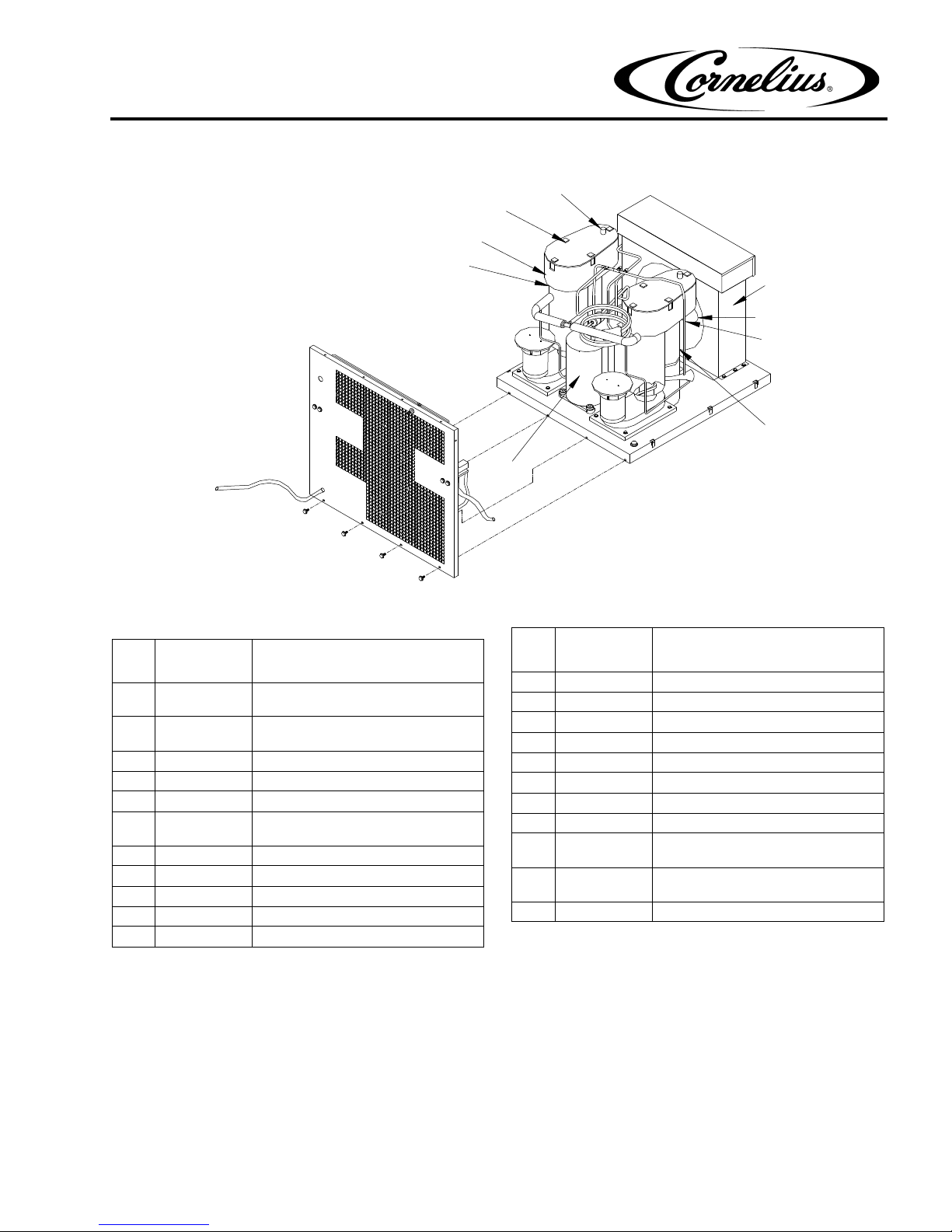
REFRIGERATION AND ICEMAKER ASSEMBLY MODEL 2000 SERIES
Item
No
1 162964027
Part No. Name
Compressor (WCC2001 &
WCF2201)
162964046
Compressor (WCC2002 &
WCF2202)
2 638036849 Condenser (WCC & WCF Air)
27177 Condenser (WCC & WCF Water)
161870007 Condenser (WCC & WCF Remote)
3 638090344001
27185 Fan Motor (Remote 50 & 60 HZ)
4 63809034401 Fan Blade (Air)
630900246 Fan Blade (WCC & WCF Remote)
5 638004391 Bracket Fan Motor
Fan Motor (WCC & WCF Air 50 & 60
HZ)
6 638036087 Clamp, Dispense Tray
Figure 1. 2000 Series
Item
No
7 638036872001 Dispense Tray Assembly
8 630900948 Cover Dispense Tray
9 630900954 Thermostat Well
10 638036867001 Clip Cove
11 638036020001 Drop Tube Assembly
12 638092537 Cover, Electrical Box
13* 164980002 Water Regulator Valve (Water)
14* 638009755 High Pressure Switch (Water)
15* 161773003
16* 166226000
17* 166225000 Receiver (WCC & WCF Remote)
Note: * = Not Shown
Part No. Name
Pressure Switch (WCC & WCF
Remote)
Valve Head Pressure (WCC & WCF
Remote)
Publication Number: 630460174IPL 1 © IMI Cornelius Inc., 2004-2012
3
16
1
10
17
18
15
15
22
11
5
20
6
19
4
21
Front View
Right Side View
Refrigeration and Icemaker Illustrared Parts List
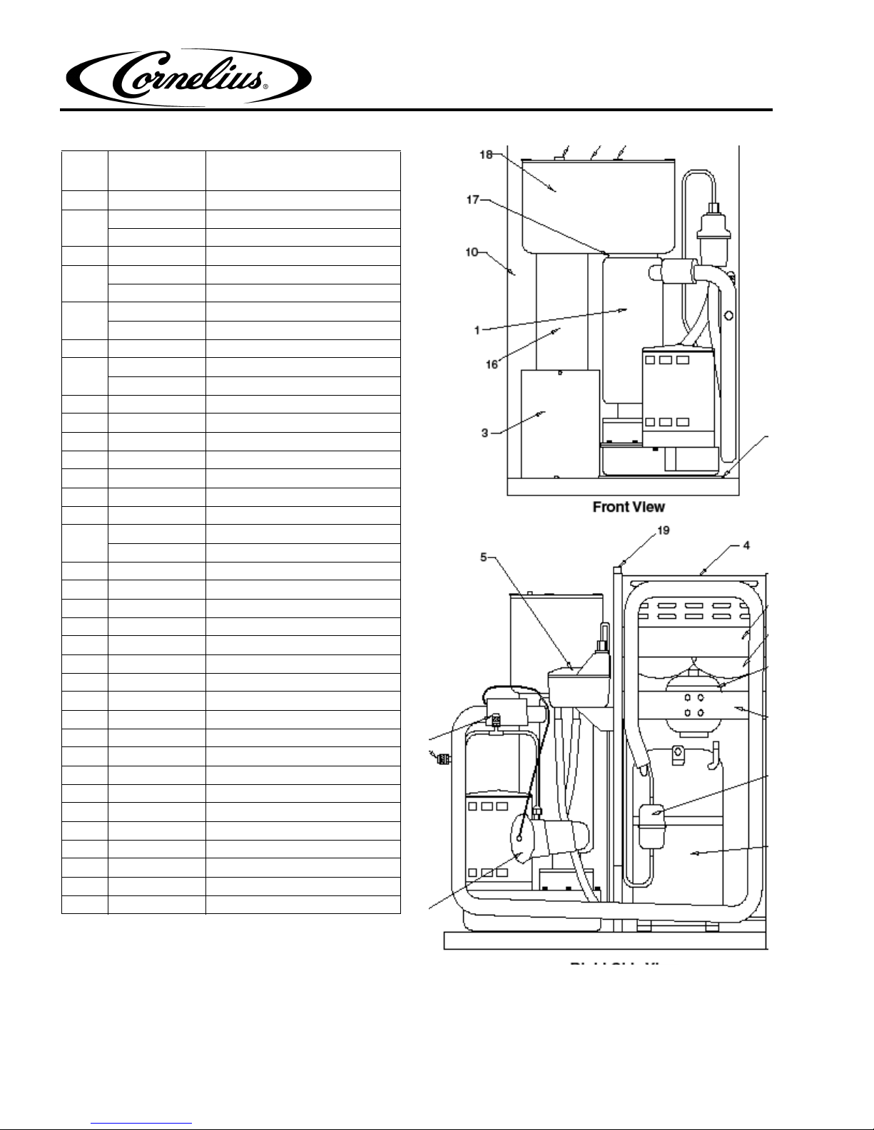
REFRIGERATION AND ICEMAKER ASSEMBLY MODEL 500 SERIES
m
Ite
No.
1 Front End Assembly
2 638090121 Compressor, 115V
3 Electrical Box Assembly
4 638008854 Condenser-Air Cooled
5 630900547 Water Level Control Assembly
6 638090126 Expansion Valve, Thermal
7 638036225 Fan Motor Assembly, 115V
8 638008618 Fan Blade
9 638008814 Bracket, Fan Motor
10 638008812 Panel, Center
11 638036218 Bracket, Mounting Icemaker
12 638008409 Bulkhead Fitting
13 638007206-04 Nut, Jam 1/2-20
14 638004393 Dryer
15 630900942 Cover, Dispense Tray
16 638036366 Drop Tube Assembly
17 638036269 Clamp, Dispense Tray
18 638036869-002 Dispense Tray Assembly
19 7231762 Gasket, Foam 3/4 X 3/4 X 13” lg.
20 20654 Access Port
21 23988 Replacement Cap
22 630901021 Thermostat Well 2”
23* 638007208-03 Nut, Palnut, 3/4–16
24* 638007295 Bulkhead Fitting, Water Cool
25* 638009755 Pressure Switch
26* 638036386 Finger Guard, Fan
27* 164980002 Water Regulating Valve
28* 638008943 Exhaust Fan Assembly
29* 161998008 Relay Start 115V
30* 161998011 Relay Start 220V 50Hz
31* 161165007 Capacitor Start 115V
32* 161165010 Capacitor Start 220V 50Hz
33* 638090123 Capacitor Run 115V
34 638036267 Fan Shroud
Note: * = Not Shown
Part No. Description
638090131 Compressor, 220V/50Hz
638036383 Condenser-Water Cooled
638008483 Reed Switch Assembly
638010017 Fan Motor Assembly, 220V 50Hz
638036867-001 Clip Cover
© IMI Cornelius Inc., 2004-2012 2 Publication Number: 630460174IPL
Figure 2. 500 Series
Refrigeration and Icemaker Illustrared Parts List
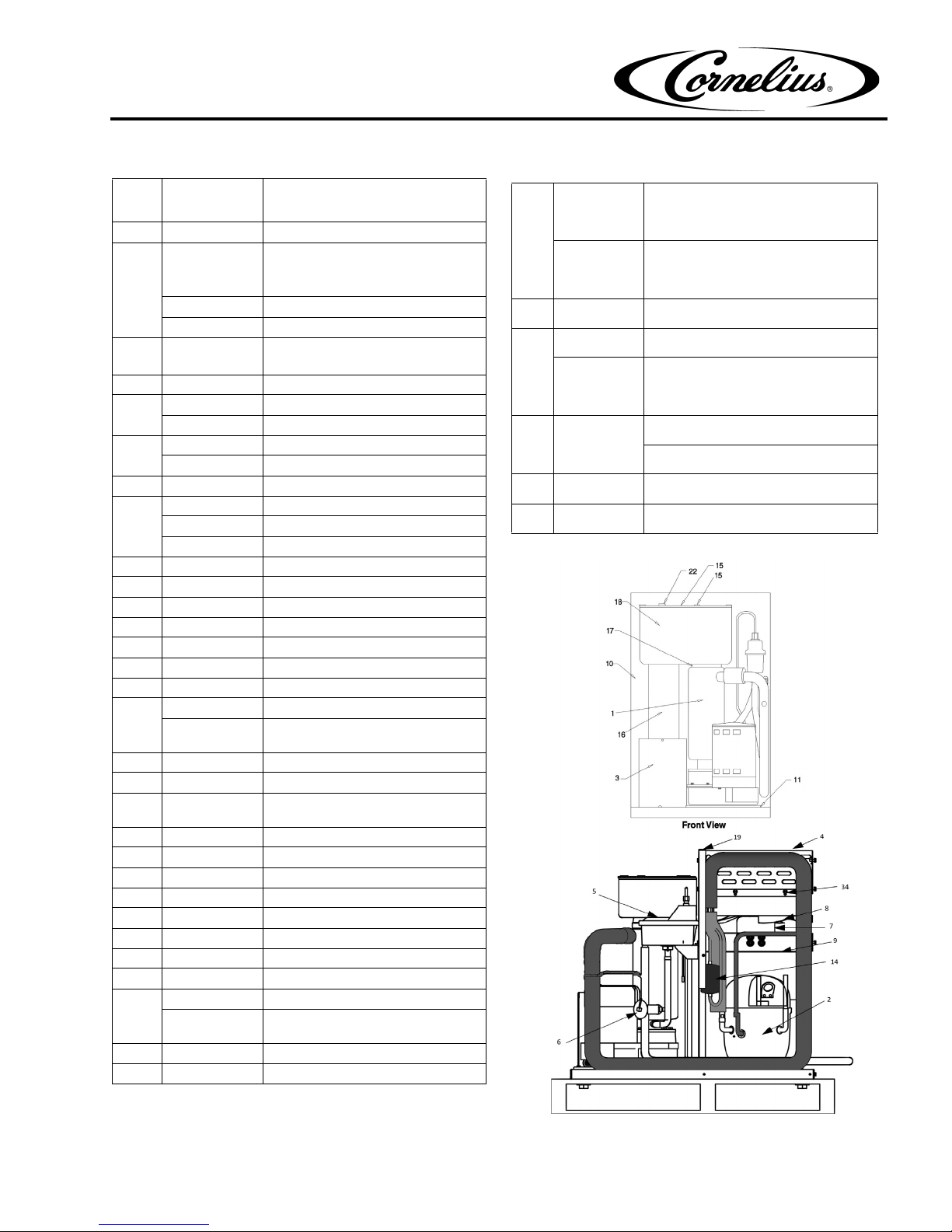
REFRIGERATION AND ICEMAKER ASSEMBLY MODEL 700 SERIES
Item
No.
1 620054225 Evap Assy WCC 700
2
3 Electrical Box Assembly
4 638036273 Condenser-Air Cool
5 630900547 Water Level Control Assembly
6 638090226 Expansion Valve, Thermal
7 638090234 Fan Motor Assembly, 208/230V
8 638096723 Fan Blade
9 638008814 Bracket, Fan Motor
10 638008812 Panel, Center
11 638036218 Bracket, Mounting Icemaker
12 638008409 Bulkhead Fitting
13 638007206-04 Nut, Jam 1/2–20
14 638004393 Dryer
15
16 638036213 Drop Tube Assembly
17 638036269 Clamp, Dispense Tray
18 638036869-
19 7231762 Gasket, Foam 3/4 x 3/4 x 13 Lg.
20* 20654 Access Port
21* 23988 Replacement Cap
22 630900953 Thermostat Well
23* 638007208-03 Nut, Palnut, 3/4–16
24* 638008834 Bracket, Mounting Condenser
25* 638009755 Pressure Switch
26* 164980002 Water Regulating Valve
27
28* 638090242 Relay Start 208/230V, 60Hz
29* 161998015 Relay Start 220V, 50Hz
Part No. Description
638090221 Compressor, 115V
For unit with S/N’s starting with 62A
and 62B
638090241 Compressor 208/230V
162964041 Compressor, 220V 50Hz
620054119 Compressor 115V
For unit with S/N’s starting with 62C
638036272 Condenser-Water Cool
638008483 Reed Switch Assembly
638090236 Fan Motor Assembly, 115V
638090233 Fan Motor Assembly, 220V 50 Hz
630900942 Cover, Dispense Tray
638036867-
001
001
161998009 Relay Start 115V RST 64
620054242 Relay Start 115V RST 64
Clip Cover
Dispense Tray Assembly
For unit with S/N’s starting with 62C
161192004
30
620054254
31* 638090123 Capacitor Run 208/230V, 60Hz
161165008 Capacitor Start 115V
32*
620054243
25335 Capacitor Start 208/230V, 60Hz
33*
34* 638090235 Condenser Shroud
35 620054256 Kit Comp Replacement WCC700
Note: * = Not Shown
Capacitor Run 115V
For unit with S/N’s starting with
62A and 62B
Capacitor Run 115V RST64
For unit with S/N’s starting with
62C
Capacitor Run 115V RST64
For unit with S/N’s starting with
62C
Capacitor Start 220V, 50Hz
Publication Number: 630460174IPL 3 © IMI Cornelius Inc., 2004-2012
Figure 3. 700 Series
3
10
11
12
16
1
9
2
18
19
5
14
13
15
4
6
7
8
17
Rear View
Left Side View
Refrigeration and Icemaker Illustrared Parts List
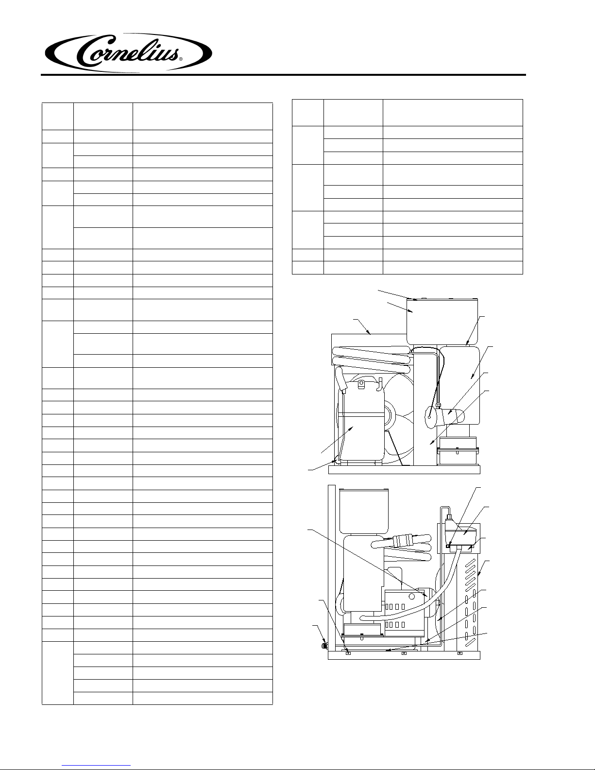
REFRIGERATION AND ICEMAKER ASSEMBLY MODEL 1000 SERIES
Item
No.
Part No. Description
1 Front End Assembly
638090321 Compressor, 208/230V
2
638090331 Compressor, 220V 50Hz
3 Electrical Box Assembly
4*638036121 Condenser-Air Cool
638009776 Condenser-Water Cool
5
638090344-
001
638090344-
Fan Motor Assembly, 208/230V
Fan Motor Assembly, 220V 50Hz
002
6 630900312 Fan Blade
7 638004391 Bracket, Fan Motor
8 638090349 Bracket, Mounting Icemaker
Item
No.
Part No. Description
63030819 Float & Stem Assembly
31
Magnet & Bracket Assembly
Float
638008483 Reed Switch Assembly WCC700/
500
32
638036069 Reed Switch Assembly WCC1000
638092531 Reed Switch Assembly WCC2000
638004717 Bracket Water Level
33
638090347 Bracket Water Level WCC1000
638092529 Bracket Water Level WCC2000
34 638008097 Clamp, Reed Switch
35 638007002-01 Screw
Note: * = Not Shown
9 638036087 Clamp, Dispense Tray
10 638036872-
Dispense Tray Assembly
001
630900948 Cover, Dispense Tray
11
638036867001
Clip Cover
630900954 Thermostat Well
12 638036020-
Drop Tube Assembly
001
13 638090350 Water Level Control Assembly
14 638036069 Reed Switch Assembly
15 638090347 Bracket Water Level
16 638090326 Expansion Valve
17 638007262-01 Nut, Tinnerman
18 638090055 Dryer
19 638008409 Bulkhead Fitting
20 638007206-04 Nut, Bulkhead Fitting
20* 638007921 Connector, UL Ground
21* 638007295 Bulkhead Fitting, Water Cool
22* 638009711 Support, Condenser, Water Cooled
23* 638009712 Clip Condenser, Water Cooled
24* 638007208-03 Nut, Palnut, 3/4–16
25* 164980002 Valve, Water Regulating
26* 638036188 Receiver, Upright
27* 638036194 Valve, Head Pressure
28* 638037110 Washer, Seal
29* 638037111 Valve, Rotolock
30* 638036014 Cover, Electrical Box
Spacer
Plunger, Rubber
Washer, Fiber
Nut
Sleeve
Nut, Compression
Figure 4. 1000 Series
© IMI Cornelius Inc., 2004-2012 4 Publication Number: 630460174IPL
 Loading...