

Page 1
Page 2

Congratulations!
Congratulations on your purchase of a state-of-the-art TFT-LCD monitor by
Korea Data Systems Co., Ltd.
We know you will be pleased with your investment and will enjoy the
dynamic viewing experience — You will never look at digital images the
same again!
Our monitor is easy to set up.
Just follow these simple instructions and you will be viewing a “new digital world”
in no time:
•
Connect the monitor to your PC.
•
Configure the monitor
•
Adjust
the display
•
Enjoy!
Copyright
© 2002 by Korea Data Systems Co., Ltd.
All rights reserved. No part of this manual may be reproduced, stored in retrieval
system or transmitted in any form or by any means electronic, mechanical or
otherwise, without the prior written permission of Koera Data Systems Co., Ltd.
Korea Data Systems Co., Ltd. is under no obligation to hold any submitted
material of information confidential unless prior arrangements are made pursuant
to Korea Data Systems Co., Ltd.’s receipt of said information. Although every
effort has been made to ensure that this manual provides up-to-date information,
please note that KDS monitor specifications are subject to change without
notice.
Part Number: 8007000007
Page 3

Table of Contents
General Information
Safety Symbols . . . . . . . . . . . . . . . . . . . . . . . . . . . . . . . . . . . . . . . . 2
Warning . . . . . . . . . . . . . . . . . . . . . . . . . . . . . . . . . . . . . . . . . . . . . 3
Caution . . . . . . . . . . . . . . . . . . . . . . . . . . . . . . . . . . . . . . . . . . . . . 6
LCD Panel . . . . . . . . . . . . . . . . . . . . . . . . . . . . . . . . . . . . . . . . . . 7
Unpacking Your Monitor and Taking Inventory of the Parts . . . . . . 8
Component Information
The Front of the Monitor . . . . . . . . . . . . . . . . . . . . .. . ... . . . . . . . . 10
The Back of the Monitor (Connection Locations) . . . . .. . . . . . .. . ... 11
Adjust the Tilt / Viewing Angle . . . . . . . . . . . . . . . . . . . .. . . . . . . 12
Power Management Function . . . . . . . . . . . . . . . . . . . . . .. . . . . . . 13
Connecting
Connect Your Monitor to Your Computer . . . . . . . . . . . . . . . . . . . . . 14
Configuring/Adjusting
Configuring and Adjusting the Display . . . . . . . . . . . .. . . . . . 17
Explanation of Remaining Menu Items / PC Mode . . . . . . . . . . . . . . 22
Troubleshooting
How to Resolve to Potential Problems . . . . . . . . . . . . . . . . . . . . 26
Appendix
CT1504 Analog Display Modes . . . . . . . . . . . . . . . . . . . . . 28
CT1504 Specifications . . . . . . . . . . . . . . . . . . . . . . . . . . . . . . . . . 29
Regulatory Compliance . . . . . . . . . . . . . . . . . . . . . . . . . . . . . . . . 30
Page 4
GENERAL INFORMATION
2
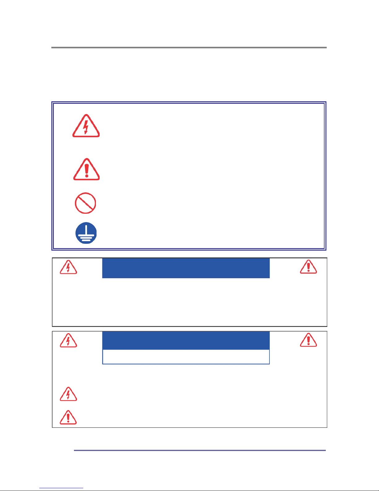
Safety Symbols
This manual uses the safety symbols below. They denote critical information.
Please read them carefully.
WARNING
Failure to abide by the information in a WARNING ma
y
result in serious injury and can be life threatening
CAUTION
Failure to abide by the information in a CAUTION may
result in moderate injury and/or property or product
damage
Indicates a prohibited action
Indicates that an electrical ground is required for
safety.
CAUTION
RISK OF ELECTRIC SHOCK · DO NOT OPEN
WARNING
TO PREVENT FIRE OR SH0CK HAZARDS, DO NOT EXPOSE THIS UNIT TO RAIN OR MOISTURE.
ALSO, DO NOT USE THIS UNITS POLARIZED PLUG WITH AN EXTENSION CORD RECEPTACLE
OR OTHER OUTLETS UNLESS THE PRONGS CAN BE FULLY INSERTED.
REFRAIN FROM OPENING THE CABINET AS THERE ARE HIGH VOLTAGE COMPONENTS INSIDE.
REFER SERVICING TO QUALIFIED SERVICE PERSONNEL.
CAUTION : TO REDUCE THE RISK OF ELECTRIC SHOCK, DO NOT REMOVE COVER OR BACK OF THIS SYSTEM.
THERE ARE NO USER SERVICEABLE PARTS INSIDE. REFER SERVICING TO QUALIFIED SERVICE PERSONNEL
.
This symbol warns the user that uninsulated voltage within the unit may have sufficient magnitude to
cause electric shock. Therefore, it is dangerous to make any kind of contact with any part inside this
unit.
This symbol alerts the user that important literature concerning the operation and maintenance of this
unit has been included. Therefore, it should be read carefully in order to avoid any problems.
Page 5

GENERAL INFORMATION
3
WARNING
If the unit begins to emit smoke, smells like something is burning or
makes strange noise, disconnect all power connections immediately and
contact your dealer for advice.
Attempting to use a malfunctioning unit can be dangerous.
Do not dismantle the cabinet or modify the
unit.
Dismantling the cabinet or modifying the unit
may result in electric shock or burn.
Refer all servicing to qualified service
personnel.
Do not attempt to service this product yourself as
opening or removing covers may expose you to
dangerous voltage or other hazards.
Keep small objects or liquids away from the unit.
Small objects accidentally falling through the
ventilation slots into the cabinet or liquid spilling
into the cabinet may result in fire, electric shock
or equipment damage.
If an object or liquid falls or spills into the cabinet,
unplug the unit immediately. Have the unit checked
by a qualified service engineer before using it again.
Set the unit in an appropriate location.
Not doing so may cause damage and could
result in fire or electric shock.
Do not place outdoors.
Do not attemp to use in a moving vehicle (ship,
aircraft, train, automobile, etc.)
Do not install in a dusty or humid environment.
Do not place in a location where steam will
come in direct contact with the screen.
Do not place near heat generating devices or
a humidifier.
Page 6
GENERAL INFORMATION
4
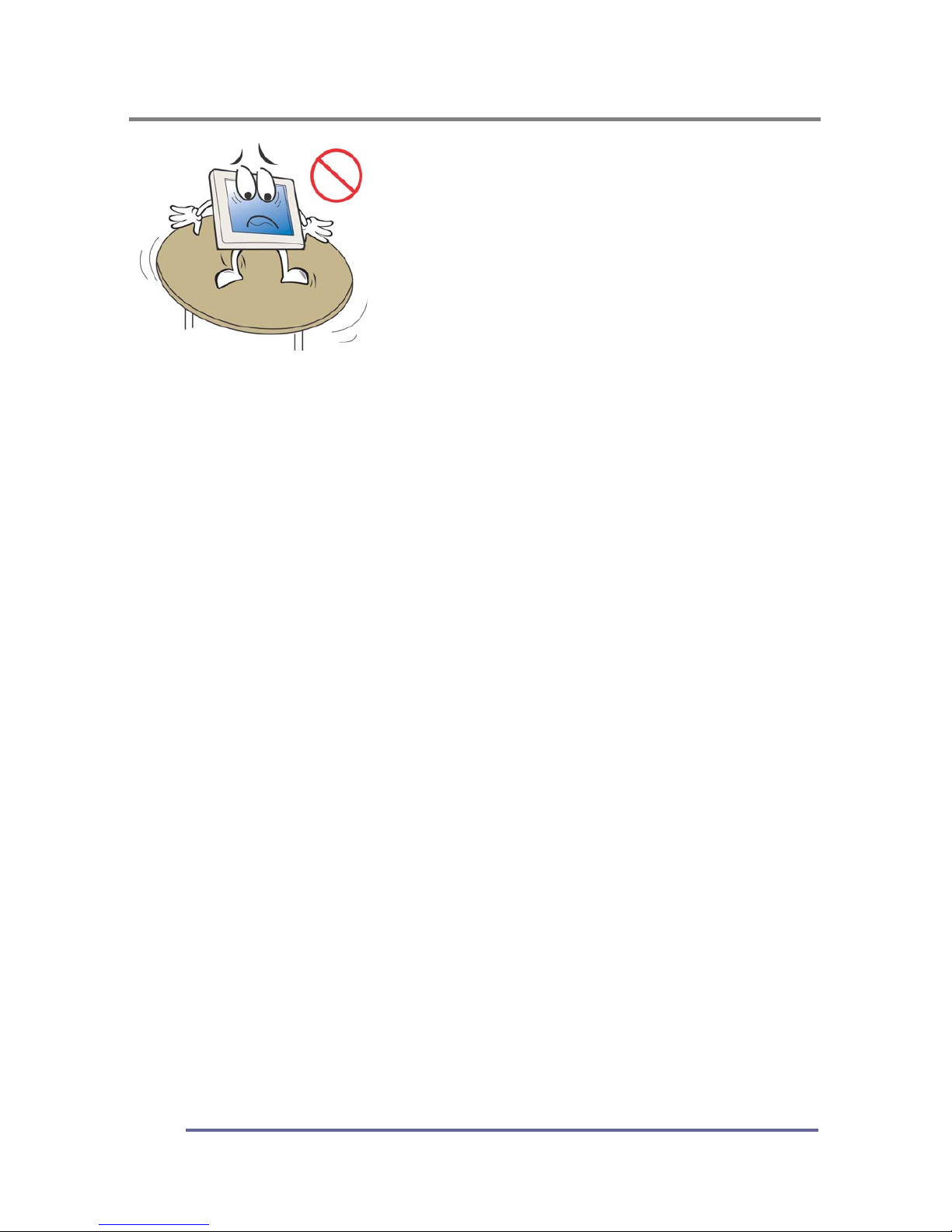
Place the unit on a strong, stable surface
A unit placed on an inadequate surface may fall,
resulting in injury or equipment damage.
When the unit is dropped, please ask your dealer for
advice.
Do not continue using a damaged unit. Using a
damaged unit may result in fire or electric shock
To avoid danger or suffocation, keep the plastic packing bags away from
babies and children.
When attaching an arm stand, please follow the directions listed in the
user’s manual of the arm stand and install the unit securely with the
enclosed screws.
Not doing so may cause the unit to come unattached, which may result in injury
or equipment damage. When the unit is dropped, please ask your dealer for
advice. Do not continue using a damaged unit. Using a damaged unit may result
in fire or electric shock. When reattaching the tilt stand, please use the same
screws and tighten them securely.
Do not touch a damaged LCD panel directly with bare hands.
The liquid crystal which leaks from the panel is poisonous if it enters the eyes or mouth.
If any part of the skin or body comes in direct contact with the panel, please
wash thoroughly. If physical symptoms result, please consult your doctor.
Use the enclosed power cord and connect to a standard power outlet of
your country. Be sure to remain within the rate voltage of the power cord.
Not doing so may cause fire or electric shock.
Use the correct voltage.
The unit is designed for use with a specific voltage only. Connection to a voltage
other than that specified in this user’s manual may cause fire, electric shock or
other damage.
Do not overload your power circuit, as this may result in fire or electric shock.
Follow local regulations and laws for safe disposal.
The backlight of the LCD panel contains mercury.
Page 7
GENERAL INFORMATION
5
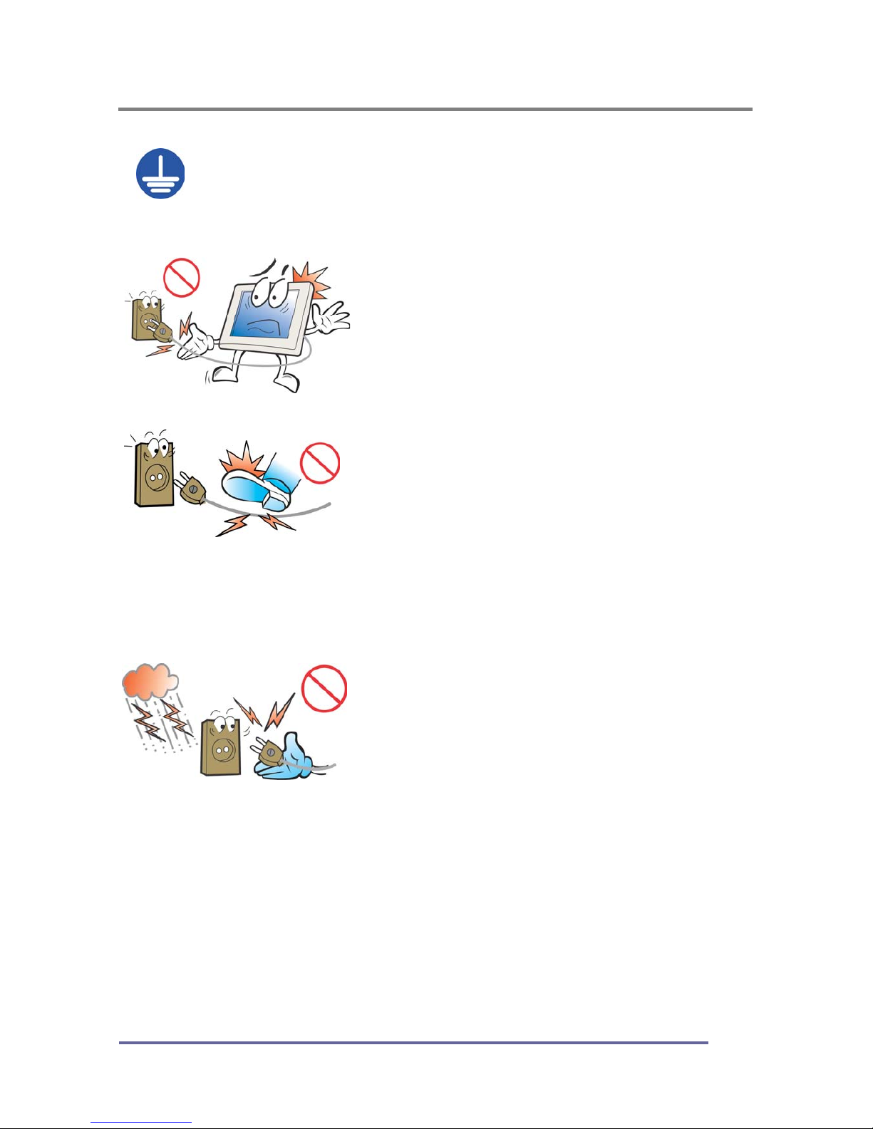
The equipment must be connected to a grounded main outlet.
Not doing so may cause fire or electric shock.
To disconnect the power cord, grasp the
plug firmly and pull.
Never tug on the cord, doing so may cause
damage and could result in fire or electric shock.
Handle the power cord with care.
Do not place the cord underneath the unit or
other heavy objects.
Do not pull on or tie the cord.
If the power cord becomes damaged, stop
using it. Use of a damaged cord may result in
fire or electric shock.
Never touch the plug or power cord if it
begins to thunder.
Touching them may result in electric shock.
Page 8

GENERAL INFORMATION
6
CAUTION
Handle with care when moving the unit.
Disconnect the power cord and cables when moving the unit. Moving the unit
with the cord attached is dangerous. It may result in injury or equipment damage.
When handling the unit, grip the bottom of the unit firmly with both hands,
ensuring the panel faces outward before lifting.
Dropping the unit may result in injury or equipment damage.
Do not block the ventilation slots on the cabinet.
Do not place books or other papers on the
ventilation slots.
Do not install the unit in a closed space.
Do not use the unit lying down or upside-
down.
Using the unit in these ways blocks the
ventilation slots and prevents proper airflow,
which can leading to fire or other damage.
Do not touch the plug with wet hands.
Doing so may result in electric shock.
If you plan to leave the unit unused for an
extended period, disconnect the power cord
from the wall socket after turning off the
power switch for safety and power
conservation.
Use an easily accessible power outlet.
This will ensure that you can disconnect the power quickly in case of a problem
Periodically clean the area around the plug.
Buildup of dust, water or oil on the plug may result in fire.
Unplug the unit before cleaning it.
Cleaning the unit while it is plugged in to a power outlet may result in electric shock.
Page 9

GENERAL INFORMATION
7
LCD Panel
The screen may have defective pixels. These pixels may appear as slightly light
or dark areas on the screen. This is due to the characteristics of the panel itself
and not the product.
The backlight of the LCD panel has a fixed life span. When the screen becomes
dark or begins to flicker, please contact your dealer.
Do not press on the panel or edge of the frame strongly, as this will result in
damage to the screen. There will be prints left on the screen if the image on the
screen when pressed is dark or black. If pressure is repeatedly applied to the
screen, it may deteriorate or damage your LCD panel. To decrease the
possibility of prints, try to keep the images on the screen as light as possible.
Do not scratch or press on the panel with any sharp objects, such as a pencil or
pen as this may result in damage to the panel. Do not attempt to wipe with
tissues as this may scratch the LCD panel.
Page 10

GENERAL INFORMATION
8
Unpacking Your Monitor and Taking Inventory of the Parts
Please make sure the parts shown in the following figure are included with your
monitor.
If any of these items are missing or appear to be damaged, contact your dealer
or call technical support immediately.
Figure 1: Inventory of Parts
TFT-LCD monitor
Installation Guide
AC Power Cord
Stereo-Stereo Cable
Set-up CD
15-pin VGA Signal Cable
Page 11
GENERAL INFORMATION
9
When unpacking the monitor and its components:
• Carefully open the box.
• Lay the box flat on a table and carefully slide the contents out of the box.
• Do not “dump” the contents out of the box.
When inspecting the monitor and its components:
• Verify all the components are present, according to the previous figure.
• Verify the parts are not damaged.
TIP:
Save the box and other packing material in case the
Monitor needs to be returned.
NOTE:
Depending on the voltage requirements for your area,
the power cord may be different than what is indicate
d
in the figure.
Page 12
COMPONENTS
10
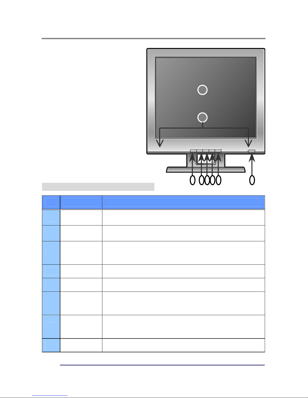
The Front of the Monitor
Figure 2: CT1504 Front of the Monitor
No. Item Function
1
LCD Panel
(screen)
15” TFT-LCD, max resolution 1024x 768, 16.2
M color.
2
Built-In
Speakers
After connecting the audio input, you can use the
speakers: 1W output
3
AUTO
Activates the auto adjustment function.
This function automatically adjusts the image’s position
on the LCD.
4
MENU Pressing this button displays the main menu.
5
SELECT
Pressing this button selects the highlighted menu item.
6
◀
Pressing this button moves to the next lower menu item.
It can also decrease the value of the parameter
displayed or change the displayed option.
7
▶
Pressing this button moves to the next higher menu item.
It can also increases the value of the parameter
displayed or change the displayed option.
8
POWER Pressing this button will turn the monitor off and on.
2
1
37546
8
Page 13
COMPONENTS
11
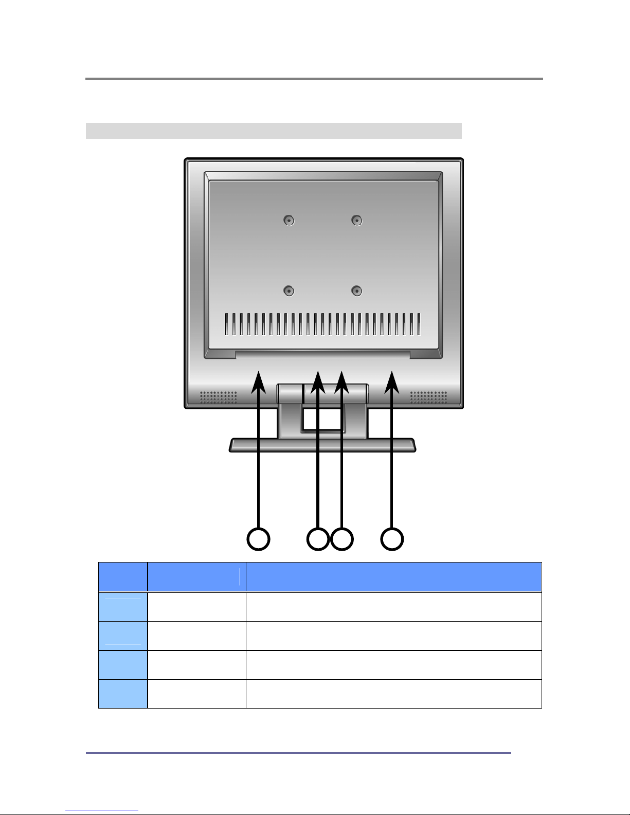
The Back of the Monitor (Connection Locations)
Figure 3: CT1504 Connection Locations (Back of the Monitor)
No. Item Function
1
PWR
AC/DC Adapter Connection
2
VGA
15-pin Connector for D-sub (Analog)
3
AUD IN
Sound in Connection
4
AUD OUT
Sound out Connection
2 4
3
1
Page 14
COMPONENTS
12
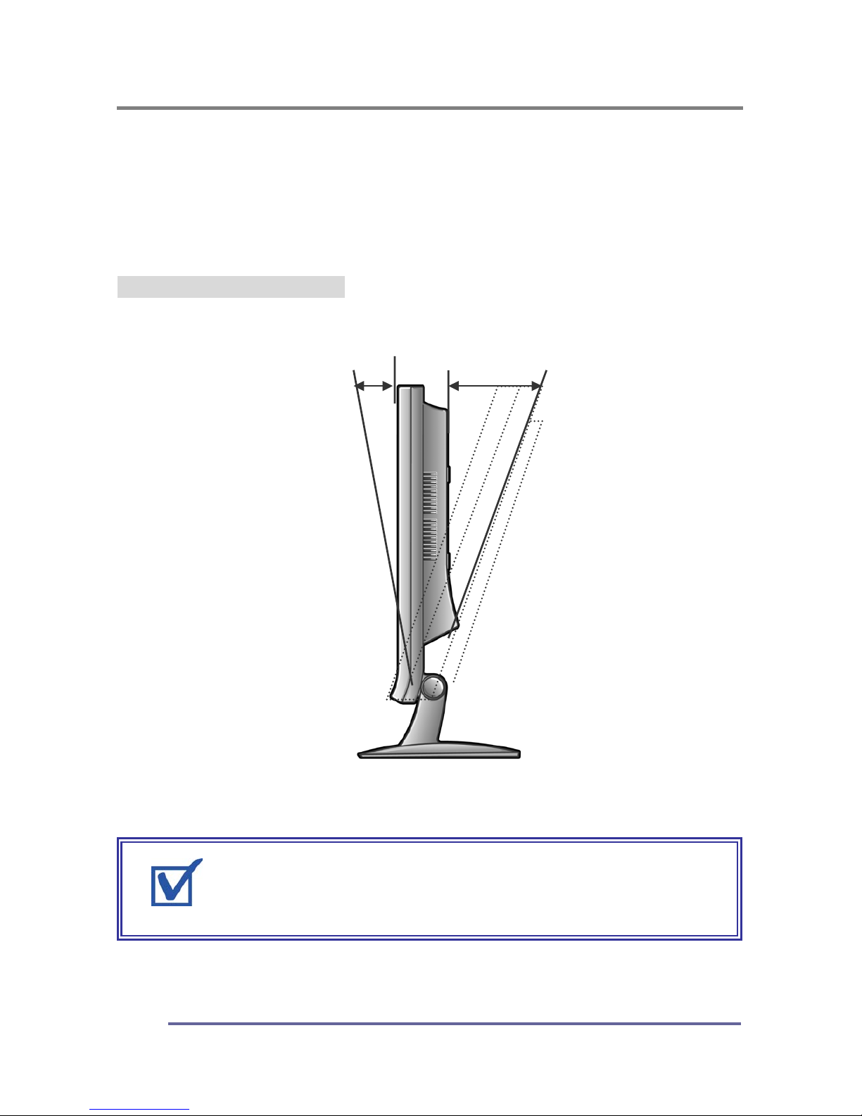
Adjusting the Tilt / Viewing Angle
Your monitor was designed to allow you to adjust it to a comfortable viewing
angle.
The monitor can be tilted forward Three degrees or back 20 degrees.
Figure 4: CT1504 Tilt Angle
3˚ 20˚
REMINDER:
To prevent the monitor from falling over, make sure i
t
is within the safe viewing angle range.
Page 15
COMPONENTS
13
Power Management Function
This monitor is equipped with a Display Power Management Signaling(DPMS)
function that automatically cuts the power dissipation down to less than 5Watt
when the computer is left unattended.
Power Light Status Description
Green
Power on.
Amber/ Blink
Power saving mode enabled.
TIP:
Although the monitor can be left in power-savin
g
mode for longer periods, we recommend that you tur
n
it off after your daily work is through.
Page 16
CONNECTING
14
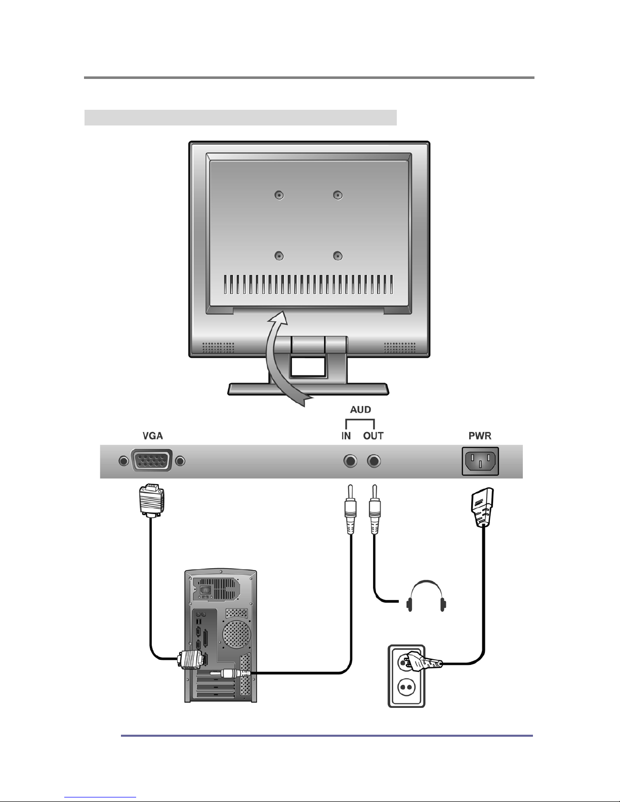
Connecting Your Monitor to Your Computer
1. Turn off and unplug your computer until instructed otherwise.
2. Carefully unpack all the components and verify that all parts are present and
undamaged see page 8.
3. Organize the cables you need and familiarize yourself with the connection
configuration for the CT1504, see pages 11 & 16.
4. Lay the monitor on a soft, clean surface with the screen facing the ground.
5. Connect the 15-pin VGA cable to the monitor’s VGA connector.
6. Connect the 15-pin VGA cable to your computer.
7. Plug the audio cable into the monitor’s AUD IN connector.
8. Connect the audio cable to your computer’s speaker card slot.
9. Connect the power flex to the monitor’s PWR connector.
REMINDER:
Using your fingers, hand-tighten the screws on the 15
-
pin connectors.
NOTE:
To use a headset, plug the headset into the AUD OU
T
connector on the monitor.
TIP:
For easier access to the cable connections, keep th
e
monitor laying screen-side down on a smooth surface.
Page 17
CONNECTING
15
10. Stand your Monitor up and adjust it to the most comfortable viewing angle
(see page 12).
11. Plug the power cords for both the monitor and computer in to the wall power
outlet or surge protector.
12. Turn both the monitor and computer on.
13. Insert the set-up CD into your computer’s CD or DVD drive and follow the
instructions (see page 17).
14. If necessary, fine-tune the display by using the on screen display (OSD)
menus (image position, brightness, etc). (see page 19-21).
15. Enjoy your new monitor from Korea Data Systems Co., Ltd.
TIP:
Save the original container and the packin
g
materials in case there are difficulties and yo
u
need to return the monitor.
REMINDER:
Do not plug the power cord into the wall outlet o
r
surge protector yet.
Page 18
CONNECTING
16
Figure 5: Monitor-to-Computer Connection Diagram
Page 19
CONFIGURING AND ADJUSTING THE DISPLAY
17
Configuring and Adjusting the Display
Using the system’s OSD menus, you can adjust and refine your monitor’s
image.
The following table describes the initial set-up steps and the other menus available.
Remember, when using the buttons on the front of your monitor:
Press the AUTO button to activate the auto adjustment function.
Press the MENU button to display the main menu.
Use the
◀ ▶
buttons to scroll through the menu items or to
increase/decrease the value/parameter.
Press the SELECT button to choose the desired menu item and to store
the new value/parameter.
★
monitor Driver Installation Procedure
1. Turn on the monitor and the computer.
2. Insert the KDS monitor Driver CD into the CD or DVD drive of
your computer.
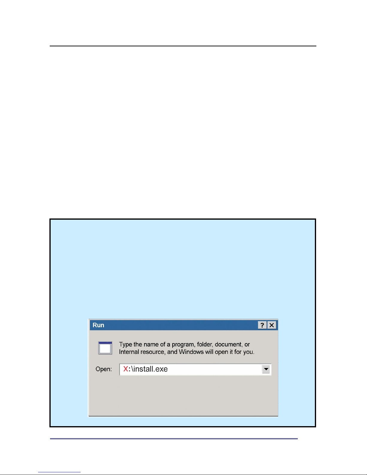
3. If the Main Menu screen dose not appear, click the Start button,
click RUN and go to Step 4. Otherwise, go to Step 5.
4. Type X:\ install.exe (replace the letter “X” with the letter
representing your CD or DVD drive), and click OK.
Page 20
CONFIGURING AND ADJUSTING THE DISPLAY
18
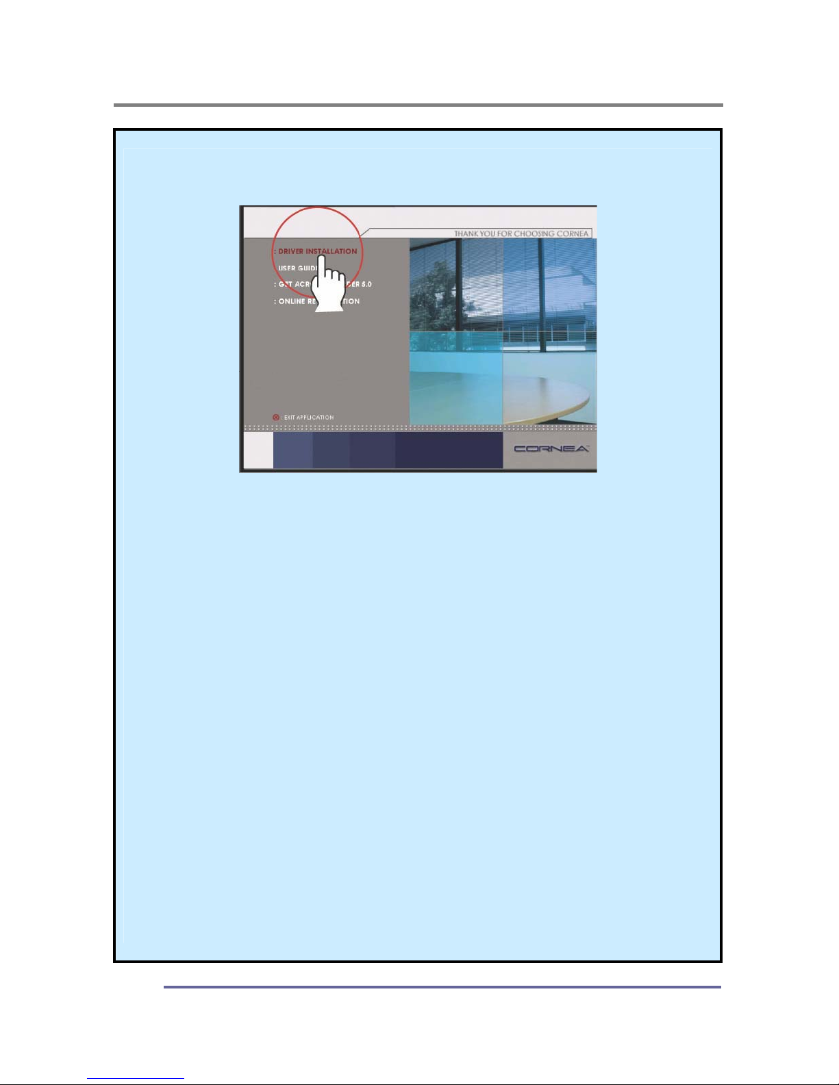
5. Click Install Driver and follow the instructions to complete the
installation.
6. To Change the Resolution or Refresh Rate:
Right Click on your desktop to open the pop-up menu(for Windows
95/98/2000/XP).
With the left mouse button, click on Properties to open the Display
Properties
menu.
Click on the
Setting
tab and change to resolution desired.
Click Apply or OK button, then click OK to keep the selected resolution.
Go back to the Display Properties menu and click on the Setting tab.
Select
Advanced Properties
and then click on
Adapter
.
In
Adapter Properties
, select
Refresh Rate
and change to the desired
rate.
Our monitors support a refresh rate up to 75Hz. For the best possible
image quality, we recommend a refresh rate of 60Hz.
If these options do not auto do not automatically pop up on your
screen, try the procedure again after installing the monitor driver.
Page 21
CONFIGURING AND ADJUSTING THE DISPLAY
19
Adjust the Initial Image:
Vertical and Horizontal Alignment
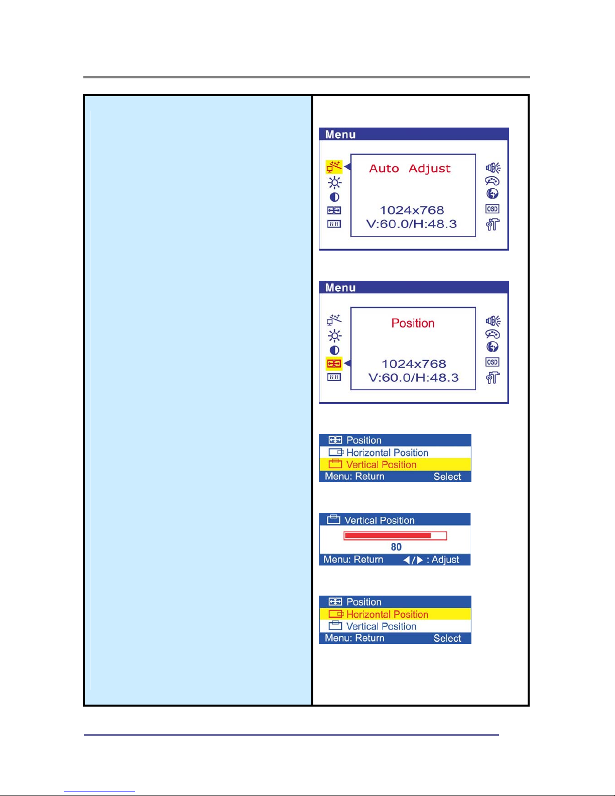
7. If it is necessary to adjust the
vertical position of the initial
display:
Press the MENU button to
display the main menu.
Press the ◀▶buttons
repeatedly to scroll to the
Position
icon.
Press the
SELECT
button to
select this menu item.
Press the ◀▶buttons
(repeatedly) to scroll to the
Vertical Position icon on the
sub-menu.
In the Vertical Position sub-
menu, use the ◀▶buttons to
move the image up or down until
it is centered vertically on the
screen.
Once you have vertically
centered the image, press the
SELECT button.
8. If it is necessary to adjust the
horizontal position of the initial
display:
Repeat the steps listed above
instead selecting
Horizontal
Position from the sub-menu.
Remember to press the
SELECT
button when the
display is centered horizontally.
CT1504 Main Menu:
CT1504 Position Sub-Menu:
Vertical Position:
Vertical Position Sub-Menu:
Horizontal Position:
Page 22
CONFIGURING AND ADJUSTING THE DISPLAY
20
Adjust the Clarity of the lmage:
Phase
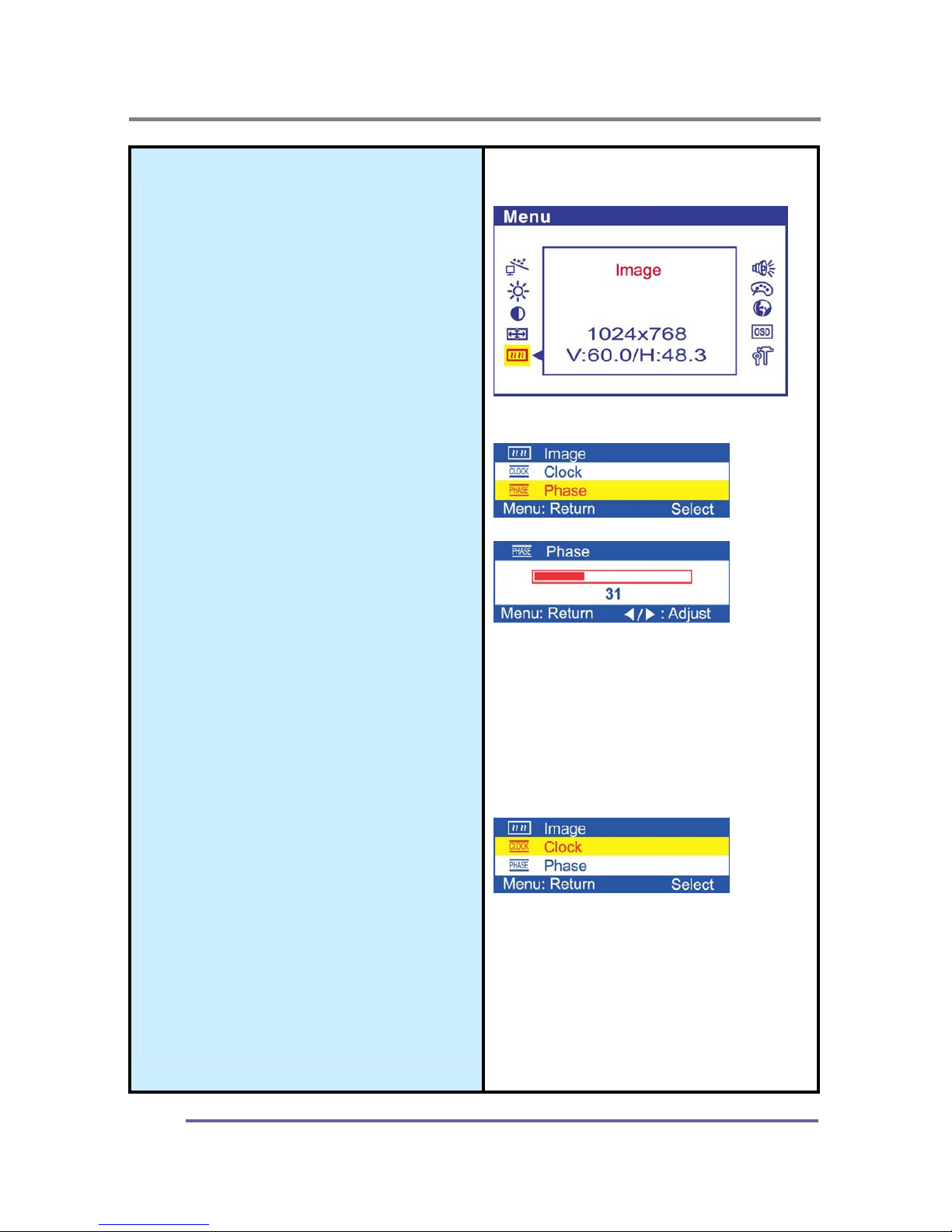
9. If it is necessary to adjust the
clarity of the image:
Press the
MENU
button to
display the main menu.
Press the ◀▶buttons
repeatedly to scroll to the
Image
icon.
Press the
SELECT
button to
select this menu item.
Press the ◀▶buttons
repeatedly to scroll to the
Phase
icon on thesub-menu.
In the
Phase
sub-menu, press
the ◀▶buttons to adjust the
clarity of the image.
Once you have the clarity set
to your liking, press the
SELECT button.
Clock
10. If it is necessary to tune a
rough image:
Repeat the steps listed above
instead chosing Clock on the
sub-menu.
Remember to press the
SELECT button when you
have the image set to your
liking.
lmage:
Phase:
Clock:
Page 23
CONFIGURING AND ADJUSTING THE DISPLAY
21
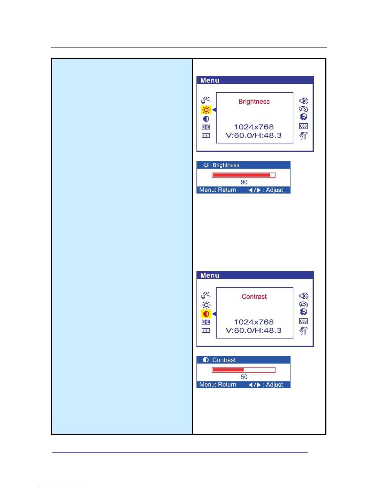
Adjust the Brightness and
Contrast:
11. To change the overall image
and brightness of the
background screen:
Press the
MENU
button to
display the main menu.
Press the ◀▶buttons
repeatedly to scroll to the
Brightness icon.
Press the SELECT button to
choose this menu item.
Press the ◀▶buttons to adjust
the brightness of the image.
Once you have the brightness
set to your liking, press the
SELECT
button.
12. To change image brightness in
relation to the background:
Press the MENU button to
display the main menu.
Press the ◀▶buttons
repeatedly to scroll to the
Contrast icon.
Press the SELECT button to
choose this menu item.
Press the ◀▶buttons to adjust
the contrast of the image.
Once you have the contrast set
to your liking, press the
SELECT button.
Brightness
Contrast
Page 24
CONFIGURING AND ADJUSTING THE DISPLAY
22
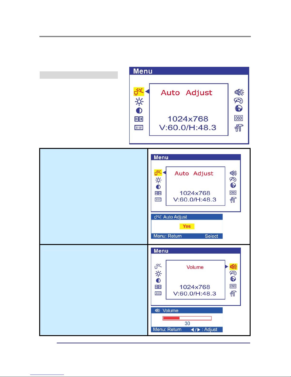
Explanation of Remaining Menu Items/ PC Mode
The following table describes the other menus available.
Figure 9: The Main Menus:
Auto Adjust
Activates the auto-adjustment
function.
This function automatically
adjusts the image’s position on
the LCD.
Volume
Adjusts the speaker volume.
Page 25
CONFIGURING AND ADJUSTING THE DISPLAY
23
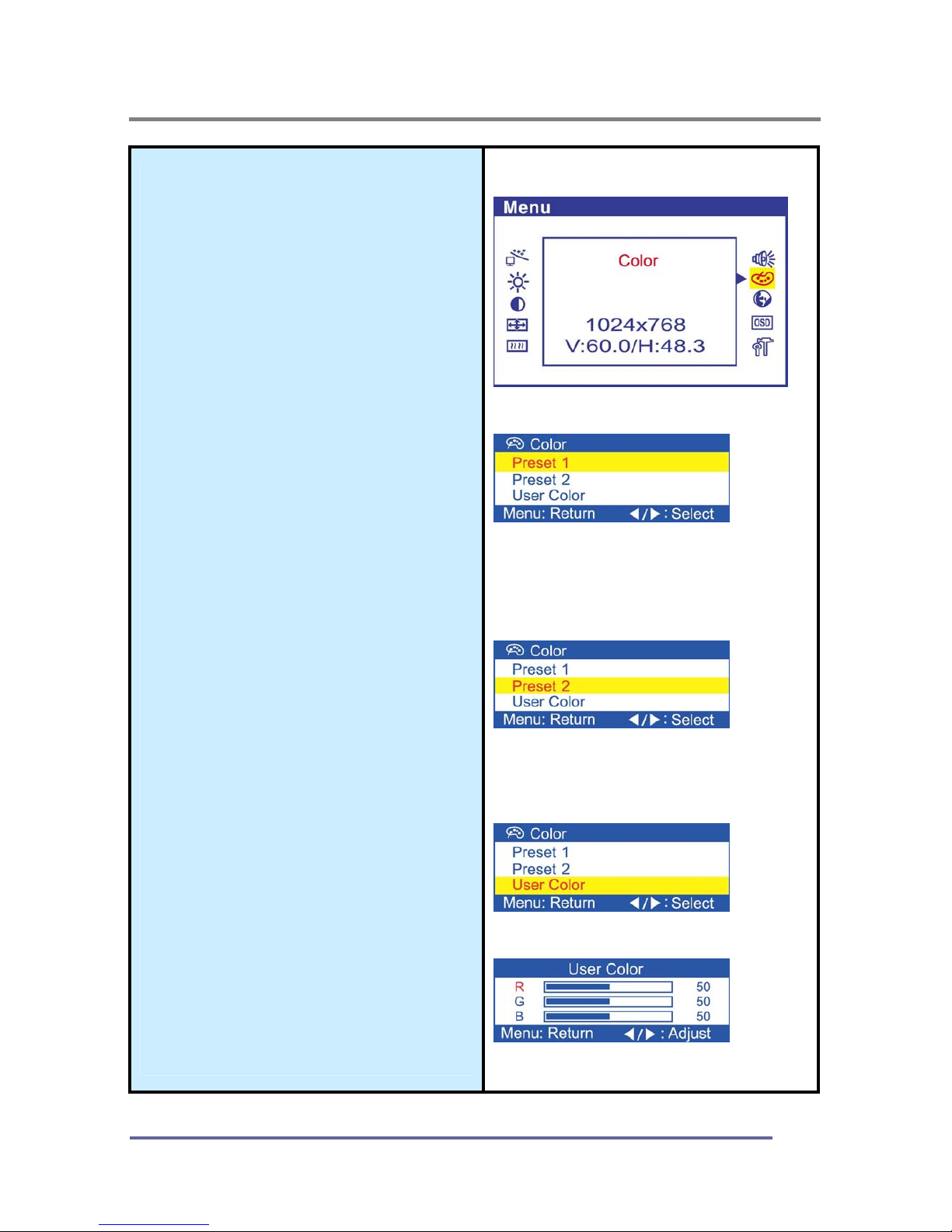
Color
Fine-tunes the viewing of color
images and background
settings.
Preset 1
Sets the background as bluish-
white.
Preset 2
Sets the background as plain
white.
User Color
Controls the individual levels of
red, green and blue.
Page 26
CONFIGURING AND ADJUSTING THE DISPLAY
24
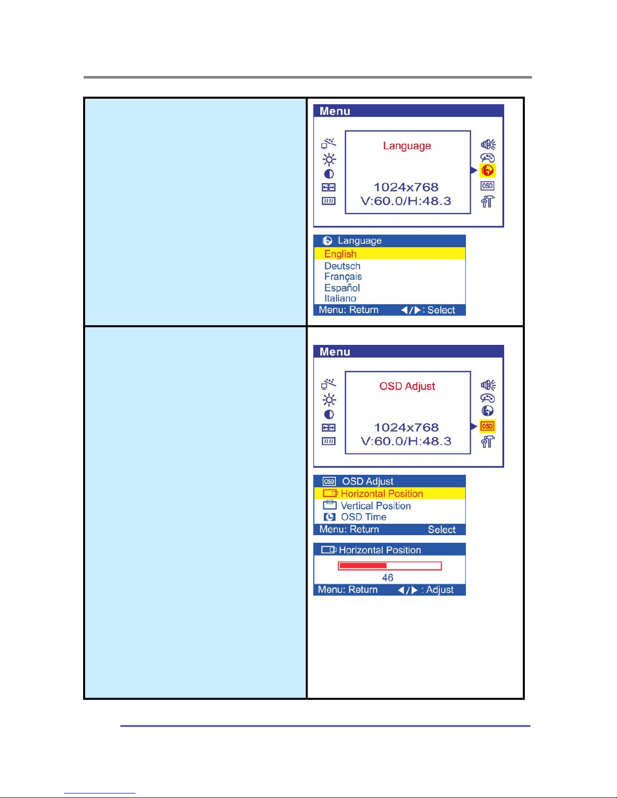
Language
Controls the language used
by the OSD menu promts.
Available languages are
English, Deutsch, Français,
Español, Italiano.
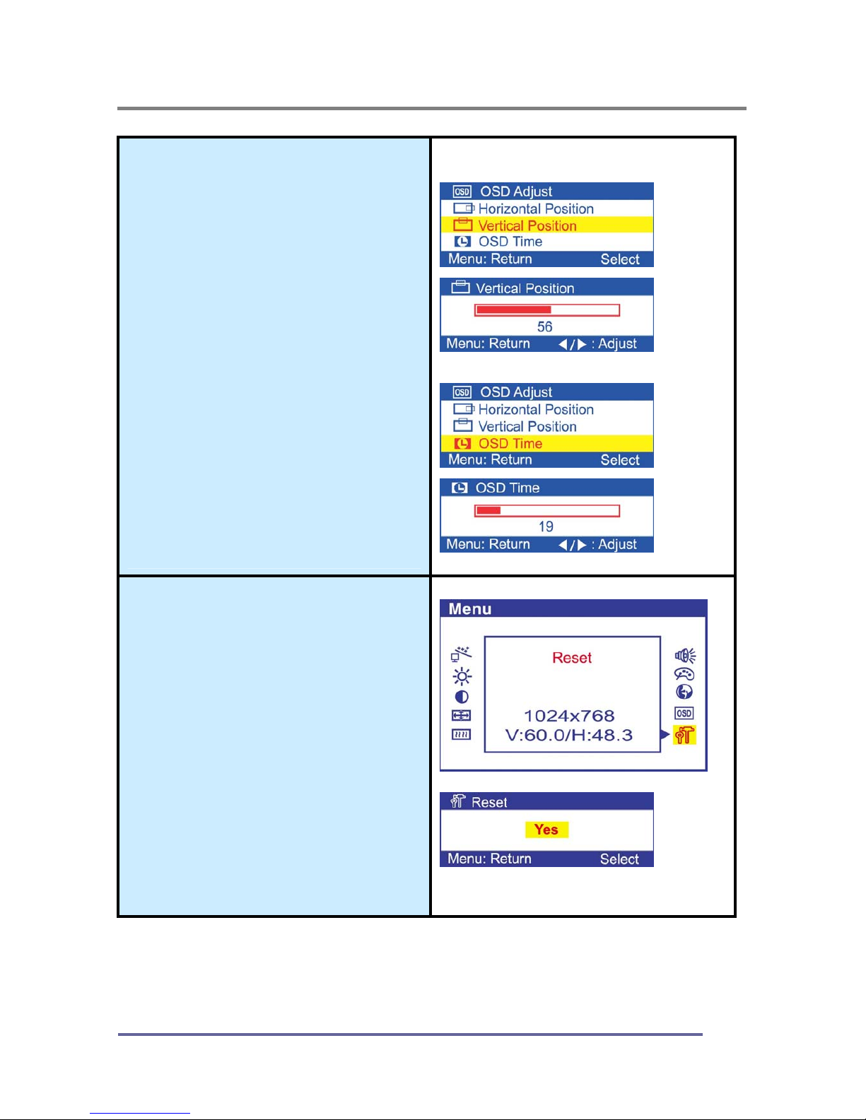
OSD Adjust
Horizontal Position
Controls the horizontal
position of the OSD.
Page 27
CONFIGURING AND ADJUSTING THE DISPLAY
25
Vertical Position
Controls the vertical position
of the OSD.
OSD Time
Controls the OSD display
time during the absence of
user control.
Reset
Displays the factory-preset
settings.
Page 28
TROUBLESHOOTING
26
How to Resolve Potential Problems
This section tries to anticipate potential problems that you may encounter in the
day-to-day use of your monitor and aims to provide simple solutions to solve the
problem before it becomes more severe.
If, after trying the suggested solutions, your monitor’s continues to experience the
same problems, contact your authorized service center or call technical support.
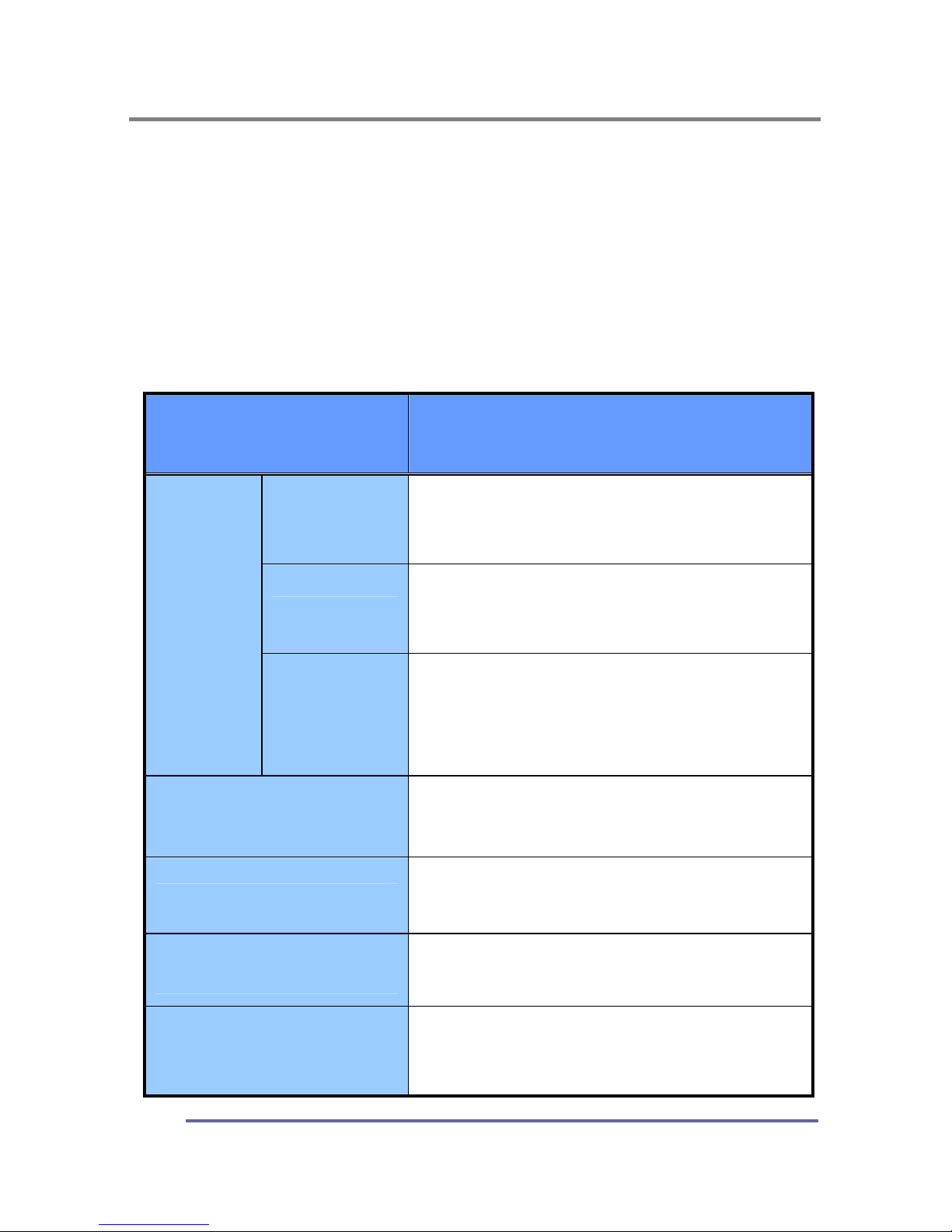
Troubleshooting scenarios
Problems Corrective Actions
LED ON
Using the OSD menu adjust the brightness
and contrast ratios to the maximums or
reset to their default settings.
LED OFF
Check the power switch and make sure the
AC power cord is properly connected to the AC
adapter.
NO
PICTURE
LED AMBER
OR BLINKING
Make sure the video signal cable is
properly connected at the back of monitor
and check to make sure the power to your
computer system is on.
DISPLAY IS NOT CLEAR
Adjust the frequency and phase settings
using the OSD menu.
DISPLAY IS DARK
Adjust the brightness and contrast settings
using the OSD menu.
IMAGE IS NOT
CENTERED
Adjust the horizontal and vertical position
settings using the OSD menu.
“OUT OF RANGE”
MESSAGE POPS UP
Check to make sure the resolution and the
frequency of the monitor are set within the
range require by your computer’s video port.
Page 29
TROUBLESHOOTING
27
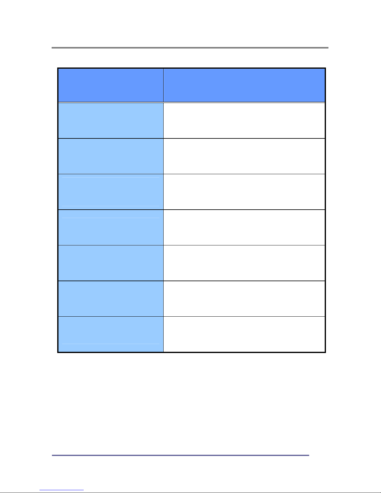
Problems Corrective Actions
PICTURE IS SCRAMBLED
Check the signal cable connection between
your computer and monitor.
PICTURE IS FUZZY
Perform auto-adjustment function.
PICTURE BOUNCES OR
HAS WAVY
OSCILLATIONS
Check the signal cable connection between
your computer and monitor.
PICTURE APPEARS TO
BE “GHOSTING”
Check the signal cable connection between
your computer and monitor.
COLOR IS NOT UNIFORM
Adjust the color settings using the OSD
color menu.
COLORS ARE
DISTORTED WITH DARK
OR SHADOWED AREAS
Adjust the color settings using the OSD
color menu.
POWER INDICATOR IS
BLINKING AMBER
The monitor is using its power
management system. Check the power
management utility on your computer.
Page 30
APPENDIX
29
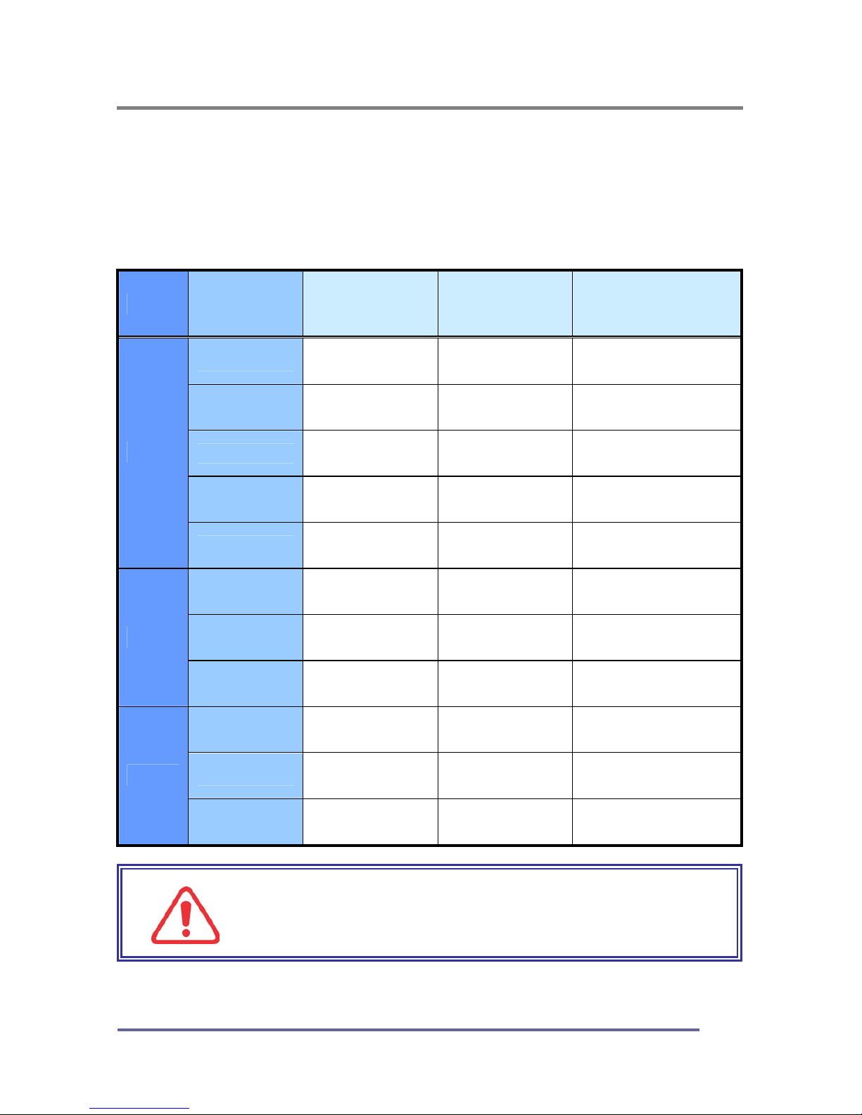
CT1504 Display Modes (Analog)
For the display modes listed below, the screen image has been optimized during
production.
Preset Timing Modes (Analog)
Mode
Display
Mode
Horizontal
Frequency
(KHz)
Vertical
Frequency
(Hz)
Standard Type
640 x 350 31.5KHz 70Hz
IBM
720 x 400 31.5KHz 70Hz
IBM
640 x 480 31.5KHz 60Hz Industry Standard
640 x 480 37.9KHz 72Hz VESA Standard
VGA
640 x 480 37.5KHz 75Hz VESA Standard
800 x 600 37.9KHz 60Hz VESA Guidelines
800 x 600 48.0KHz 72Hz VESA Standard
SVGA
800 x 600 46.9KHz 75Hz VESA Standard
1024 x 768 48.4KHz 60Hz VESA Guidelines
1024 x 768 56.5KHz 70Hz VESA Standard
XGA
1024 x 768 60.0KHz 75Hz VESA Standard
IMPORTANT:
This Monitor is not supported outside of the display
modes listed above.
Page 31

APPENDIX
30
CT1504 Specifications (Type:S0H)
“
Note :
Design and Specification are subject to change without notice.
Weight and Dimensions shown are approximate”
Type 15" (38.1Cm) Viewable Diagonal TFT Type
Pixel Pitch 0.297 mm (H) x 0.297 mm (V)
Viewable Angle
(CR ≥ 5)
Horizontal : ± 80˚ (Left/Right), TN Wide Angle
Vertical : +50˚ / -80˚ (Up/Down)
LCD
Viewable
Size
Glass Surface Haze 25, Anti-Glare, Hard-Coating (3H)
Contrast Ratio 500:1 (Typical)
Response Time 25ms (Rising + Falling)
Display Mode Normally White
Brightness 450 cd/ m2 (Typical)
INPUT VGA
RGB Analog, H/V Separate (TTL)
Fh : 31 to 61 KHz Fv : 56 to 75 Hz
Input Resolution From VGA up to 1024 x 768 at 60Hz
I/O Connectors
VGA 15-pin D-sub, DC Power-in
Stereo Audio-In/Out
Power AC 110~240V, 1.5A , 50/60Hz Input
User Controls
Brightness, Contrast, Color, Color Temperature,
Auto-Adjustment, Clock, Phase, H/V Position, 5 OSD
Languages, Volume, Reset
Displayable color 16.2 M (Full Color)
Displayable Area 304.128mm (H) x 228.096mm (V)
Operation 0°C ~ 40°C (32°F ~ 104°F)
Temperature
Storage -20°C ~ 60°C (-4°F ~ 140°F)
Dimensions Physical 352.0 mm (W) x 368.0mm (H) x 170.0mm (D)
Net 3.4Kg (7.50lbs)
Weight
Gross 5.2Kg (11.46 lbs)
Regulations
MIC, UL/cUL, CE, FCC-B, VCCI, TCO99,
ISO13406-2, EPA Energy Star
Plug and Play VESA DDC 2B
Power Management VESA DPMS Compatible
Page 32

APPENDIX
31
Regulatory Compliance
Canadian Department of Communications Compliance Statement
DOC: This Class B digital apparatus meets all requirements of the Canadian
Interference-Causing Equipment Regulations.
C-UL: Bears the C-UL Mark and is in compliance with Canadian Safety
Regulations according to C.S.A. C22.2 No. 950.
U.S.A
U.S.FEDERAL COMMUNICATIONS COMMISSION RADIO FREQUENCY
INTERFERENCE STATEMENT INFORMATION TO THE USER
NOTE : This equipment has been tested and found to comply with the limits for a
Class B digital device, pursuant to part 15 of the FCC Rules.
These limits are designed to provide reasonable protection against harmful
interference in a residential installation.
This equipment generates, uses, and can radiate radio frequency energy, and, if
not installed and used in accordance with the instructions, may cause harmful
interference to radio communications.
However, there is no guarantee that interference will not occur in a particular installation.
If this equipment does cause harmful interference to radio or television reception, which
can be determined by turning the equipment off and on, the user is encouraged to try to
correct the interference by one or more of the following measures:
Reorient or relocate the receiving antenna.
Increase the separation between the equipment and receiver.
Connect the equipment into an outlet on a circuit different from that to which
the receiver is connected.
Consult your dealer or an experienced radio/TV technician for help.
Change or modification not expressly approved by the part responsible for
compliance could void the user’s authority to operate the equipment.
Connecting of peripherals requires the use of grounded shielded signal cables.
Page 33
APPENDIX
32
Notice for Japan
This is a Class B product based on the standard of the Voluntary Control Council
for Interference from Information Technology Equipment (VCCI). If this is used
near a radio or television receiver in a domestic environment, it may cause radio
interference. Install and use the equipment according to the instruction manual.
CE Conformity
The device complies with the requirements of the EEC directive
89/336/EEC as amended by 92/31/EEC and 93/68/EEC Art.5
with regard to “Electromagnetic compatibility,” and 73/23/EEC as
amended by 93/68/EEC Art.13 with regard to “Safety.”
 Loading...