


series 65 80
Minitransporter
CORMIDI
srl
This manual should always be readily available so that the machine operator may
consult it immediately, and it must be saved for the entire duration of the machine’s life.
© 2010 - The entire or partial reproduction and/or divulging of this document is prohibited in any form without the written consent of the manufacturing company. The
editing of the text, the illustrations, and the paginations were realized by “Cormidi s.r.l.” The information and technical data were furnished, checked and validated by
the Cormidi Technical Office. The illustrations and technical data included in this manual are non binding: the manufacturer reserves the right to carry out
eventual modifications to its product without notice.
Ed. 1
USER’S MANUAL AND MAINTENANCE
leadinginnovation
Via Fonte, 342
84069 Roccadaspide (SA)
0828 943689 Fax 0828 943963
www.cormidi.com info@cormidi.com

Series 65-80
INTRODUCTION
Dear Customer,
We would like to take this opportunity to thank you
for your confidence in us shown by purchasing a
CORMIDI Minitransporter. This product was designed
and constructed for longevity and to be used with
maximum reliability.
It is, however, absolutely necessary to read this
manual carefully in which the procedure for optimum
use of the equipment is described: improper use may
provoke harm to oneself and cause injury to persons
and/or to one’s health.
Therefore, always keep this manual within easy
reach so that it may be consulted at any time, before,
during, and after use. If the machine is resold, do not
forget to give it to the new owner in that inside there
is the EC compliance certificate.
We would like to remind you that the illustrations
contained in the manual correspond for the most part
to the base model and that our models are regularly
improved and perfected with the goal of allowing our
customers to enjoy the maximum benefits of
innovations in technology: for this reason the
characteristics and the information contained in the
present manual may have been varied recently. We ask
you to contact us in case you should encounter
difficulty.
Remember for supplementary information you can
always contact your sales representative/dealer, or you
can contact us directly by telephone or by email at
info@cormidi.com
. If there is any doubt, it is better to
ask rather than proceed on your own.
We leave you to your perusal of the manual and
enjoyment of your machine!
Staff CORMIDI Srl

1. GENERAL INFORMATION
1.1. W
ARRANTY
Your machine is guaranteed for 12 months from the
date of its delivery and includes the substitution of
anything in particular that has resulted as, in the opinion of
our Technical Office, affected by construction defects.
Any part in particular that was not constructed by the
manufacturer, parts used in/on terrain surfaces, and
breakdowns caused by incompetence or carelessness,
including fuelling, are excluded from the guarantee.
The motor, instead, is covered under the manufacturer
of the motor’s own warranty according to the foreseen
conditions and terms.
The guarantee immediately expires if the machine is
utilized for uses different from those foreseen by the
Manufacturer, if it is damaged by the use of unauthorized
accessories or if it is repaired using unsuitable parts.
With the machine a Certificate of Warranty was
supplied which outlines the norms which regulate the
service of assistance under warranty. We highly
recommend reading the warranty form to fully
General Information
understand the various rights and responsibilities.
Collaborate with your sales representative when filling out
the form and make sure it is filled out correctly, in that the
text and the other formalities (shipment within the time
limit, etc.) represent the legal base for the warranty on the
machine.
1.2. G
OAL OF THE MANUAL
This manual has been drawn up by the
manufacturer and is an integral part of the machine: it
was written in Italian, the native language of the
manufacturer (1.7.4 - 2006/42/CE).
The information contained here within is addressed
to expert operators, equipped with specific knowledge
and competence in the sector of use. The manual
defines the objectives for which the machine was
designed and constructed.
To avoid incorrect manoeuvres that risk accident, it
is important to read this manual particularly before the
first use to familiarize oneself with the principal
commands and their functions.
A constant observance of the information
1
Series 65-80
READ CAREFULLY: economy of use, and a
dangerous
voke serious injury or
On the machine potential dangers have
been indicated with a sticker characterized by
potentially
that can provoke
serious injury or death if the instructions are
On the machine the warnings are indicated
orange band
tuation that can provoke injury
or damage to the machine if the instructions
s
yellow band with black text.
IBITED: prohibitions that must be
observed by all persons who interact directly
and/or indirectly with the machine so that
guarantees safety, economy of use, and a longer
functional duration of the machine.
To give a higher prominence to the sections of the text
which must not be ignored, they have been highlighted in
bold and preceded with symbols illustrated and defined
following here:
longer functional duration of the machine.
DANGER: indicates imminently
situations that can pro
death if the instructions are not followed.
a red band with white text.
WARNING: indicates a
dangerous situation
not followed.
with stickers characterized by an
with black text.
CAUTION: indicates a potentially
dangerous si
are not followed.
On the machine situations requiring
caution are indicated by sticker
characterized by a
PROH
risks may be limited.
1.3. M
ACHINE DESCRIPTION
The Series 65-80 machines are compact autounloading tracked vehicles that are equipped with a
body and sometimes with other auto-loading
equipment, designed and manufactured for the
exclusive use of transporting inert materials.
To satisfy the various requirements of the market,
the machine may be equipped with motors that have
similar power but that have different brand names and
characteristics.
2
General Information
READ CAREFULLY: Determine the type of
motor that has been installed in your
read its manual to
READ CAREFULLY: The information
contained here is essential for your safety and
e operated
PROHIBITED: It is strictly prohibited to use
this machine for the transport of persons
PROHIBITED: It is strictly prohibited to use
to tow other machines, vehicles,
and/or devices, not even temporarily or in an
REQUIRED: Always wear suitable work
clothes and above all suitable work shoes
Always use protective hearing
away
et
substitute missing or illegible ones. Respect all
regulations contained in these.
machine accurately, and
familiarize yourself with it.
1.4. S
AFETY INFORMATION
for that of your co-workers!
During the production of this machine, every possible
measure was taken to make your work safer. Simple
prudence, however, is essential: there is no better rule to
prevent accidents.
WARNING: The tool must always b
by a competent and well-trained operator.
Carefully read the information before using the
machine or before performing maintenance and/or
repairs.
A few minutes of your time spent reading this manual
will save you time and effort later on.
Carefully read the warnings and information written
on the signs on the machine and immediately
The machine was made exclusively for the
transportation of inert materials. Any other use is
prohibited.
and/or animals.
this machine
emergency situation.
The machine constitutes a work instrument: always
respect the national regulations, especially those
relative to safety at the place of work.
diligently.
devices.
WARNING: Never wear large or flyclothes (scarves, ties) that could easily g
caught in the moving parts.
It is always advisable to have a first aid kit close at
3
Series 65-80
DANGER: Never use the machine inside
enclosed areas because the gasses emitted
REQUIRED: Carry out the disposal of oils,
minerals, and harmful products with respect
ccordance with
icle when the
motor is on or hot, in the proximity of flames
or while smoking. Always keep the machine
cleaned of lubricant and/or combustible
PROHIBITED: It is strictly prohibited to
remove protection and safety devices with
DANGER: While working always be sure that
the terrain has the required consistency and
avoid working on the edge of embankments,
ditches, or ravines or on excessively steep or
CAUTION: Never leave the machine
unattended while the motor is on, not even
temporarily: when you leave the area, turn off
e and put on the
DANGER: Never let children play with the
hand.
Before turning on the motor, always be sure that
there are not any people, animals, or things that
could be an obstacle in the work area.
by the exhaust are lethal.
for the environment and in a
the current norms.
which the machine is equipped
Avoid working under unsuitable physical conditions
or when you are very tired: in these cases interrupt
your work.
uneven terrain.
Every intervention for cleaning, tuning, and/or
maintenance must be done under good
environmental conditions and with adequate light,
and always with the motor turned off.
DANGER: Never refuel the veh
residues.
Pay careful attention to not come into contact with
the overheated parts of the motor.
4
When putting away the machine take all precautions
so that it might not be moved or turned on by
incompetent or incapable persons.
the motor of the machin
parking brake!
machine, not even if it is turned off!

1.5. M
PROHIBITED: it is strictly prohibited to use
the machine with its safety devices and
protection removed, blocked, or in any way
WARNING: Before beginning work, verify the
working order of the safety devices and
out and/or broken parts
ACHINE AND MANUFACTURER IDENTIFICATION
The data which identifies the machine and the
manufacturer are listed on the aluminium plate that is
affixed on the dashboard of the machine. The frame
number is stamped on the left of back side (see fig. 1).
1.6. S
AFETY DEVICES
made non functional.
substitute any wornimmediately.
General Information
1 Manufacturer
2 Machine Type
3 Serial Numero
4 Load Capacity KG
5 Machine Mass KG
6 Motor Power KW
7 Fabrication Year
8 EC Brand
0 Frame Number
fig. 1 – Identification Plate (cod. C1094.14.00)
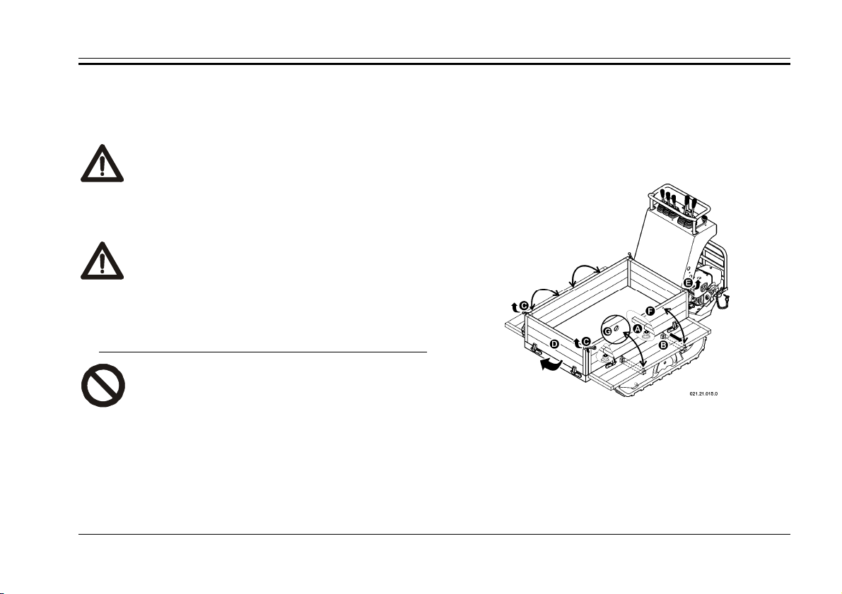
1.6.1. B
LOCKING THE BODY
The machine is equipped with a device to block the
body in the raised position and to prevent it from lowering
accidentally.
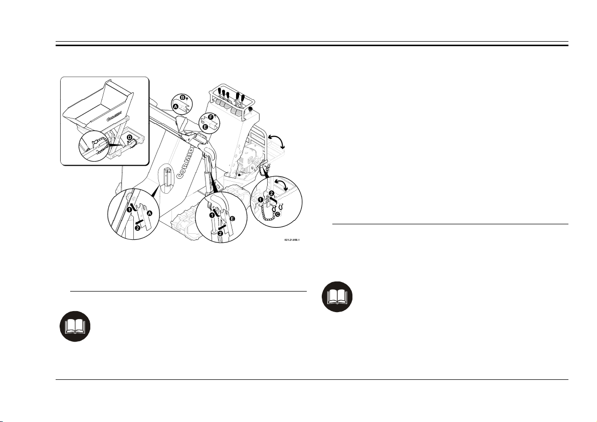
Before carrying out any repair maintenance work with
the body raised, always block the piston following this
procedure (see fig. 2):
• raise the body;
• turn off the motor;
• remove device “A” from its slot, down on the right side
of the body, by unscrewing wheel “B”;
• insert the hole of the bar on the piston of the hydraulic
jack;
• Turn the bar and position it so that it is parallel to the
5

Series 65-80
CAUTION: Always use the drive footrest
in open position during the work, to
Close the drive footrest
piston;
• slowly lower the unit with the motor off until the
correct fit of the device is obtained.
Afterwards remove the device and put it back in its slot.
1.6.2. B
LOCKING THE ARM
If necessary, the machine is equipped with a device
used to block the down-loading arm in the raised
position and prevents accidental lowering, as needed
can be placed on the piston on the left or right in a
similar manner.
Follow these steps (see fig. 2):
• Raise your arm of self-loading;
• Lift the body;
• Turn off the engine;
• Remove the safety device “E”, on the left side of the
container from the housing by loosening the knob “F”;
• Enter the slots of the bar near one of the two pistons of
hydraulic cylinders of the arm;
• Turn the bar and placed it parallel to the piston;
• Pull down slowly, with the engine off, the arm until the
frame of the device.
After the operations, remove the device and place it
back into place.
1.6.3. B
LOCKING THE FOOTREST
The drive footrest must always be blocked in open
position, during the work, to prevent its accidental
movement, by using the safety pin “C” (see fig.2).
Introduce pin “C” into hole “1” to block the footrest in the
raised position;
Introduce pin “C” in hole “2” to block the footrest in the
lowered position;
prevent risks.
only after use.
1.6.4. B
LOCKING THE LIFT
(“HI-TIP”)
The raising device for the body for high
unloading (Hi-Tip) can be blocked in a raised
position to impede accidental movement, by using
the safety pin “D” (see fig. 2).
Introduce the pin in the hole to block the mechanism in
the raised position.
6
General Information
Read the instructions
and the mode of use for the accessories that
have been installed on your machine carefully.
l that was
READ CAREFULLY: During the design phase
everything possible was done to prevent
eventual risks: where it was technically
pictograms were resorted
eventual potential and
e tags were made with
signals and descriptions associated with
pictograms to give a higher importance to
possible dangers, in accordance with
fig. 2 – Safety Devices
1.7. A
CCESSORIES
READ CAREFULLY:
Refer to the instruction manua
provided with them.
The machine is furnished with equippment to make it
possible to carry out normal maintenance operations.
It is also equipped with a hydraulic force instrument: in
the manual the instructions for its use have been
furnished.
Also, the machine the may also be equipped upon
request with particular tools including:
• Cement mixer for mixing concrete;
• Auto-loading tools;
• Excavator;
• Demolition hammer.
1.8. S
AFETY TAGS
impossible, specific
to in order to highlight
imminent risks.
Specific adhesiv
government norms UNI 9244-95 (E).
7
Series 65-80
PROHIBITED: it is strictly prohibited to
ove the stickers and the safety plates
which the machine is equipped with:
immediately substitute deteriorated and/or
8
rem
illegible ones.
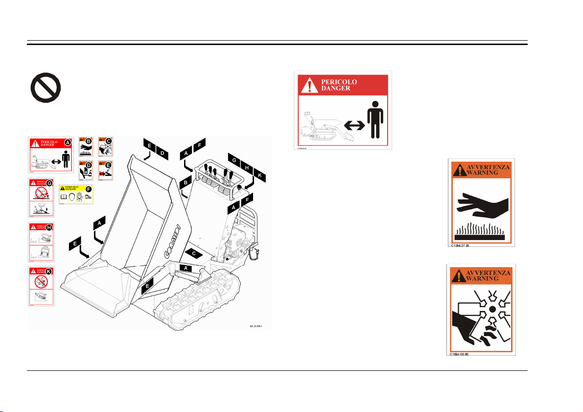
fig. 3 – Position of the SafetyTags
1.8.1. S
AFETY DISTANCE
Tag which alerts the
serious danger of coming
near and standing within the
field of action of the
machine in that there is an
imminent risk of danger.
fig. 4
(cod. C1094.02.00)
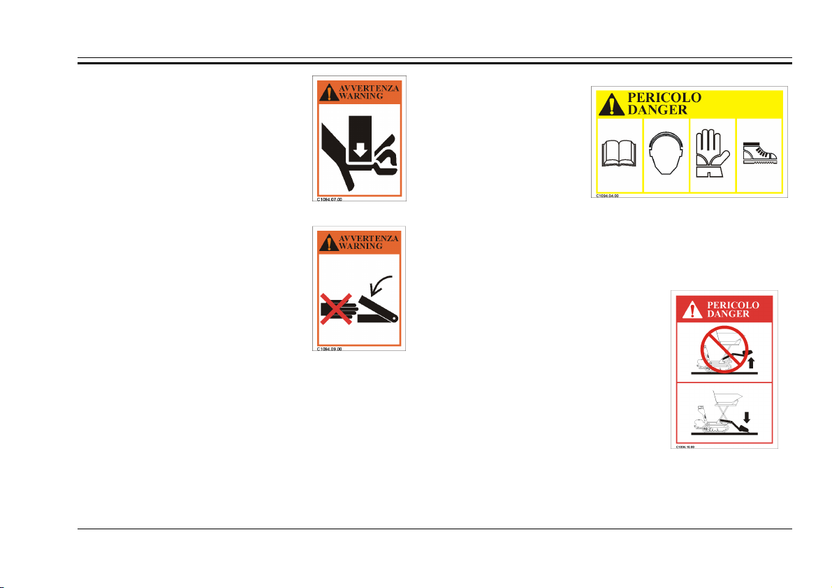
1.8.2. H
OT SURFACE
Invites caution in that there is a
risk of burning because of the
nearness to the hot surface.
1.8.3. FAN
Indicates a potential risk of
danger in that there is a possibility of
coming into contact with moving
mechanical parts that can cause
serious injury.
fig. 5
(cod. C1094.07.00)
fig. 6
(cod. C1094.08.00)
General Information
1.8.4. C
RUSHING
Tags which indicate a potential
risk of crushing that may cause very
serious injury or death.
1.8.5. C
UTTING
Tags which indicate a potential
fig. 7
(cod. C1094.09.00)
risk of cutting that may cause very
serious injury or death.
1.8.6. P
ROCEDURE FOR CAUTION
fig. 8
(cod. C1094.09.00)
This adhesive which invites caution reminds one to
adopt all anti-injury precau-tions, above all regarding the
use of protective devices and individual prevention. The
meaning of the pictograms is the following:
• Read the manual before turning the machine on for the
first time, each time an operator is changed, and in any
case in which doubt is raised as to how the machine
functions;
• Wear a headset
which protects
hearing or
another device of
this type;
• Wear protective
gloves of the
fig. 9
(cod. C1094.04.00)
prescribed type;
• Wear injury-preventive shoes of the prescribed type.
1.8.7. O
VERTURNING
Indicates an imminent risk of
overturning with serious
consequences during use of the
high unloading.
The correct procedure to carry
out high unloading includes the
necessity to rest the shovel of the
auto-loading on the ground in a
way that stabilizes the machine
before raising the body and
fig. 10
(cod. C1094.10.00)
unloading.
Instead the upper part of the tag indicates the incorrect
procedure which must be avoided absolutely, while the
9
Series 65-80
lower part shows the correct position to carry out the
unloading safely.
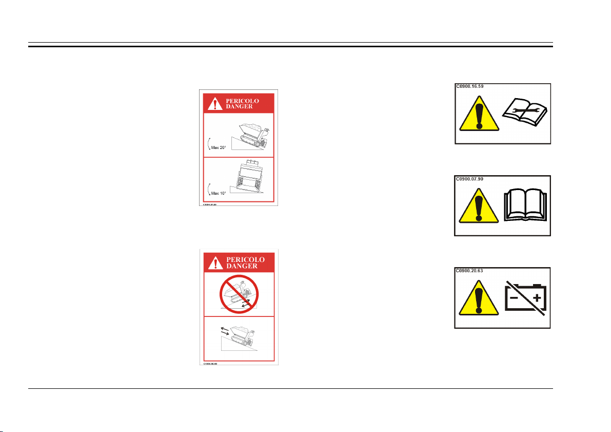
1.8.8. M
AXIMUM SLOPES
Completely avoid working on
terrains that have latitudinal slopes
of more than 10° and longitudinal
slopes of more than 20° to avoid the
possibility of overturning with
serious consequences for the safety
of the operator. In every case, but
especially in the case of slopes, it is
important that the terrain is solid
fig. 11
(cod. C1094.01.00)
and stable.
1.8.9. P
ROCEDURE FOR ADDRESSING SLOPES
Sign which indicates in what way
one must address the downhill and
uphill slopes to avoid serious
consequences for the operator and
for the machine in that there is the
potential danger of overturning.
fig. 12
(cod. C1094.06.00)
1.8.10. O
THER TAGS
The label on the side (fig.
12-a) indicates that it is
necessary to read the
documentation before any
intervention, to avoid technical
problems (ex. Manual attached
to the engine).
The label on the side (fig.
12-b) indicates that you should
read the owner's manual before
using the devices next to this
label, to avoid problems.
The label on the side (fig.
12-c) indicate the possibility of
disconnection of the battery
from the electrical circuit of
the machine; near the label
you can find the cut off
battery device (see cap. 2).
fig. 12-a
fig. 12-b
fig. 12-c
(cod. C0900.16.59)
(cod. C0900.07.90)
(cod. C0900.20.63)
10
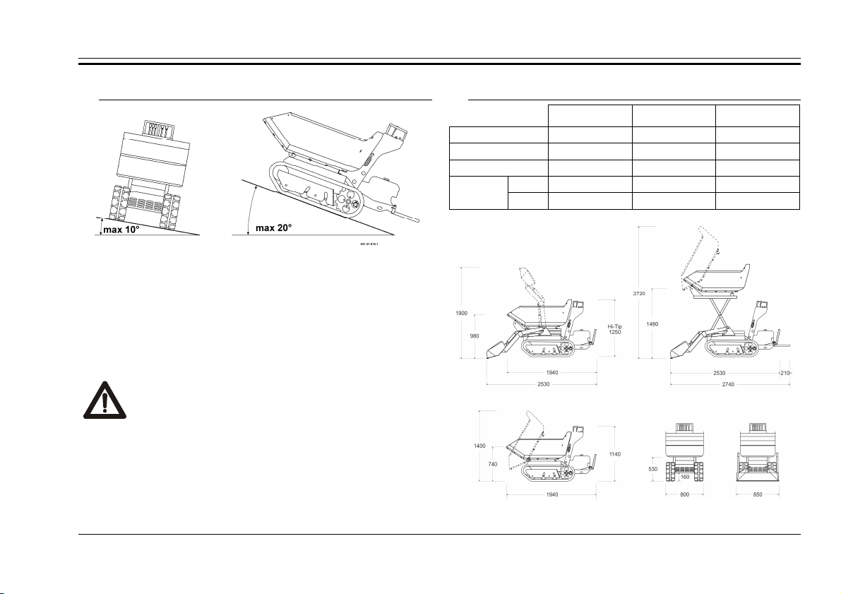
A
DANGER: Always avoid working on terrain
with slopes that are greater than those
prescribed to avoid the possibility of
overturning with possible serious
DMISSIBLE SLOPES
General Information
1.9. D
IMENSIONS
Normal Auto-loading Hi-Tip
Length 1940 mm 2530 mm 2530 mm
Width 800 mm 850 mm 850 mm
Wheel Track 610 mm 610 mm 610 mm
Height
Min 1140 mm 1140 mm 1250 mm
Max 1400 mm 1900 mm 2720 mm
fig. 13 – Maximum admissible slopes
In figure 13 the maximum values for the latitudinal and
longitudinal slopes of the terrain are shown on which it is
possible to work. These conditions must never be
surpassed to avoid the risk of overturning.
consequences for the safety of the operator.
In every case, but especially when working on slopes,
it is important that the terrain is solid and stable.
fig. 14 – Dimensions
11

Series 65-80
1.10. T
Model
Type
Mass [kg]
Engine
Power [kW]
Max Speed [km/h] - (m/s)
Load Capacity [kg]
Start-up
Accelerator
Trasmission
Parking Brake
Battery
Continuous Equivalent Pondered Acoustic Power Level A LpA =
Continuous Equivalent Pondered Acoustic
Power Level A (assured)
Vibrations Level m/s²
ECHNICAL DATA
Dumper Auto-loading Hi-Tip
9.65 10.80 13.80 9.65 10.80 13.80 9.65 10.80 13.80
430 500 450 500 580 520 630 670 650
petrol diesel petrol petrol diesel petrol petrol diesel petrol
6,7 (9,1) 7,2 (9,8) 9,3 (12,6) 6,7 (9,1) 7,2 (9,8) 9,3 (12,6) 6,7 (9,1) 7,2 (9,8) 9,3 (12,6)
4,6 (1,27) 6,5 (1,8) 4,6 (1,27) 6,5 (1,8) 4,6 (1,27) 6,5 (1,8)
650 800 650 800 650 800
Pull-start or Electric (depending on the type)
12V - 30Ah with negative at mass – petrol engine
12V - 45Ah with negative at mass – diesel engine
Type
LwA =
Manual command lever
Hydrostatic
Mechanical
9.65 10.80 13.80
99 dB(A) 100 dB(A) 100 dB(A)
101 dB(A) 101 dB(A) 101 dB(A)
on arms: ≤ 2,5 m/s²
on body: ≤ 1,1 m/s²
12
2. COMMANDS
STABLE POSIZIONE
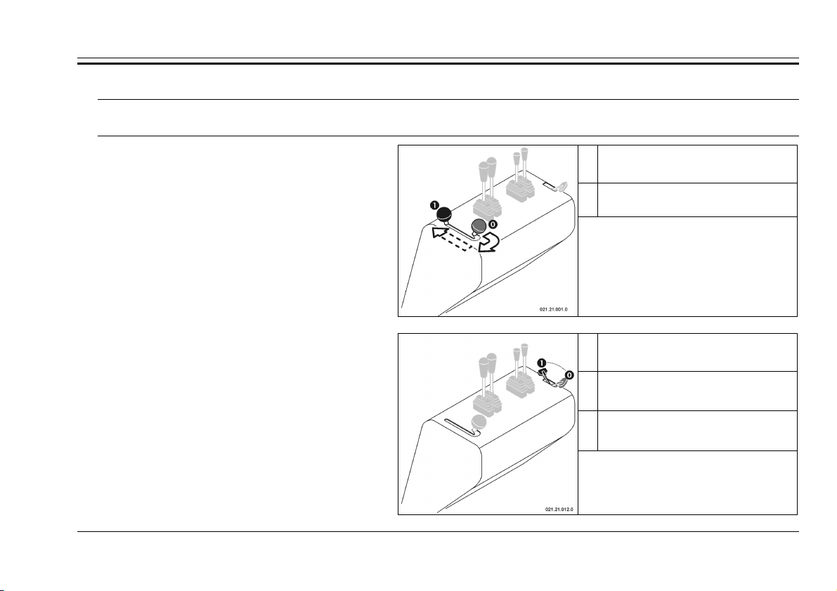
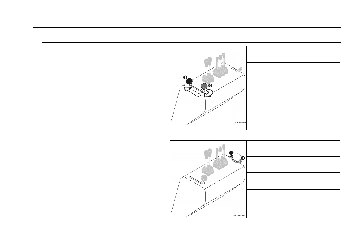
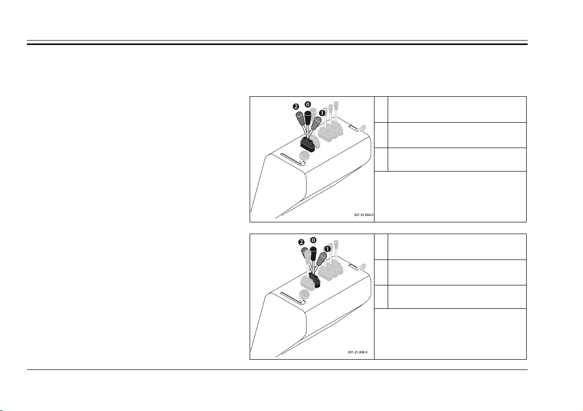
2.1. H
YDRAULIC OVERTURNING VERSION
Parking Brake Command
Commands
STABLE POSITION
Deactivated Brake
serves as an emergency brake, allows you to
insert or deactivate the brake.
Accelerator Command
so that you may obtain the required power.
The parking brake command, which also
Allows you to vary the motor rotation regimen,
Activated Brake
fig. 15
Command lever for the parking brake
STABLE POSITION
Minimum regimen
STABLE POSITION
…
Intermediate regimens
STABLE POSITION
Maximum regimen
fig. 16
Accelerator Command
13
Series 65-80
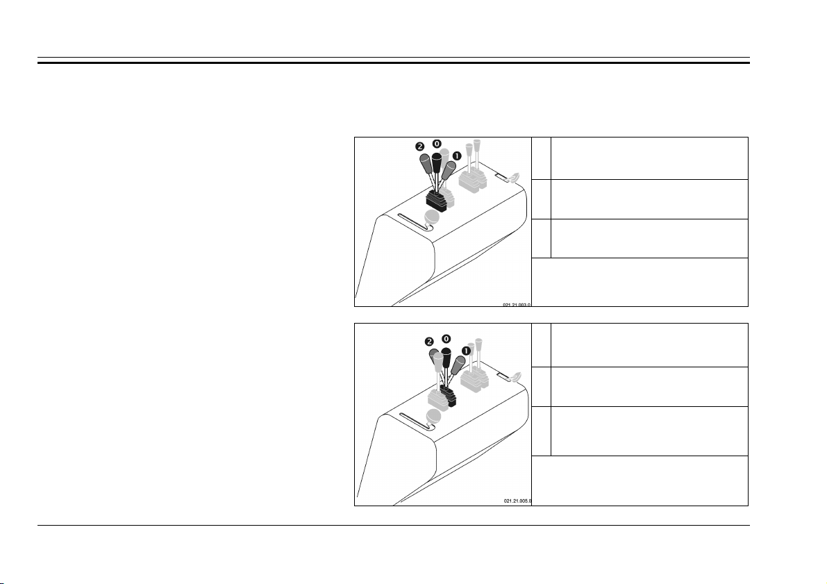
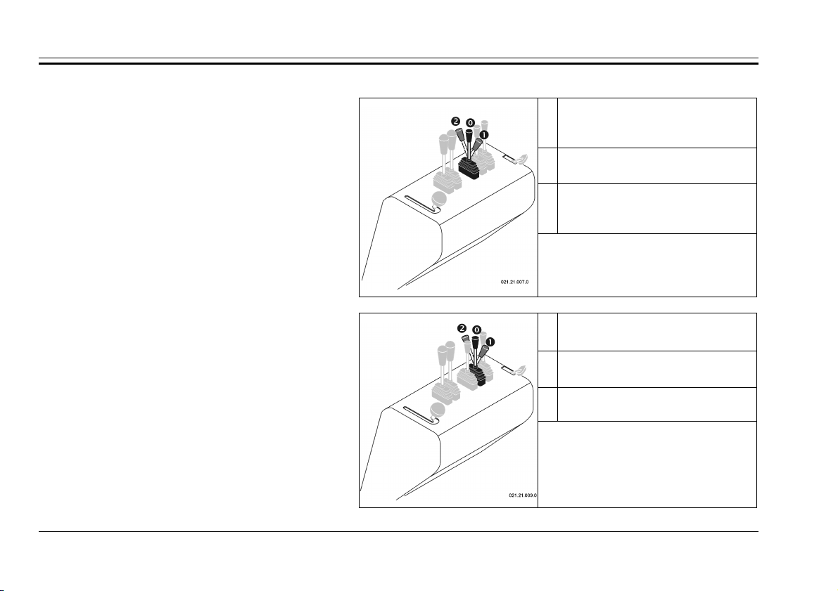
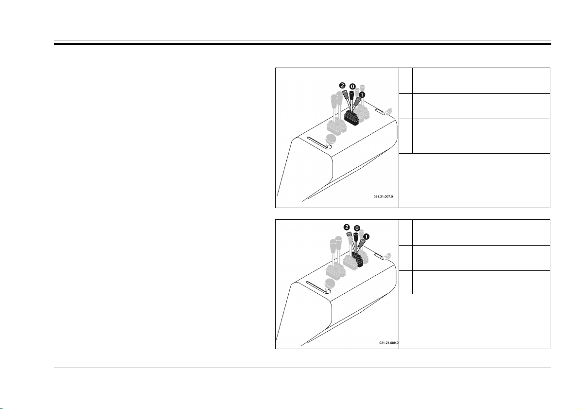
UNSTABLE POSITION
Drive Levers
The command levers control the rotation of the tracks through a hydraulic feed of the hydraulic motors.
The command levers are active only when the motor is turned on.
UNSTABLE POSITION
The left Drive Lever
The left track rotates forward
The left-hand drive lever controls the left track.
The right Drive Lever
The right-hand drive lever controls the right
track.
14
STABLE POSITION
Resting position
UNSTABLE POSITION
The left track rotates backwards
fig. 17
Command lever for the left track
UNSTABLE POSITION
The right track rotates forward
STABLE POSITION
Resting position
The right track rotates
backwards
fig. 18
Command lever for the right track
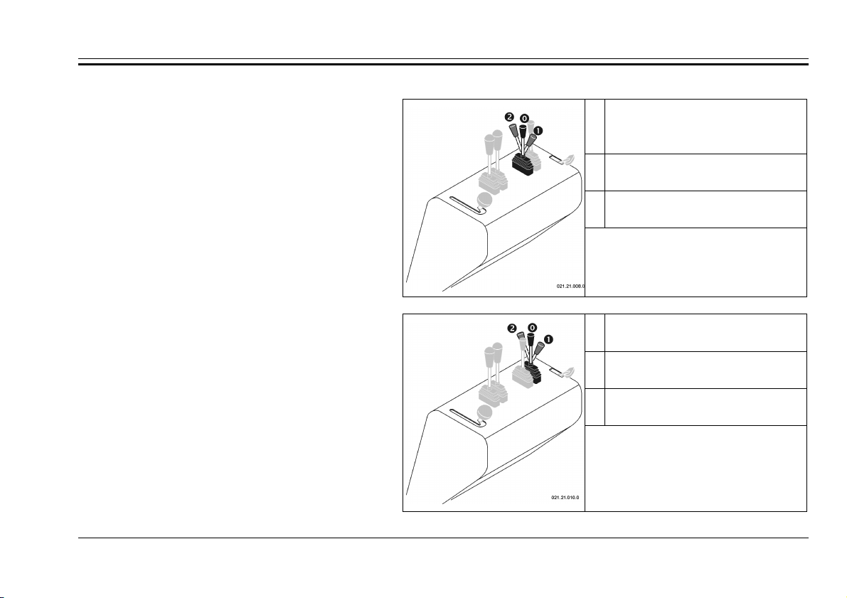
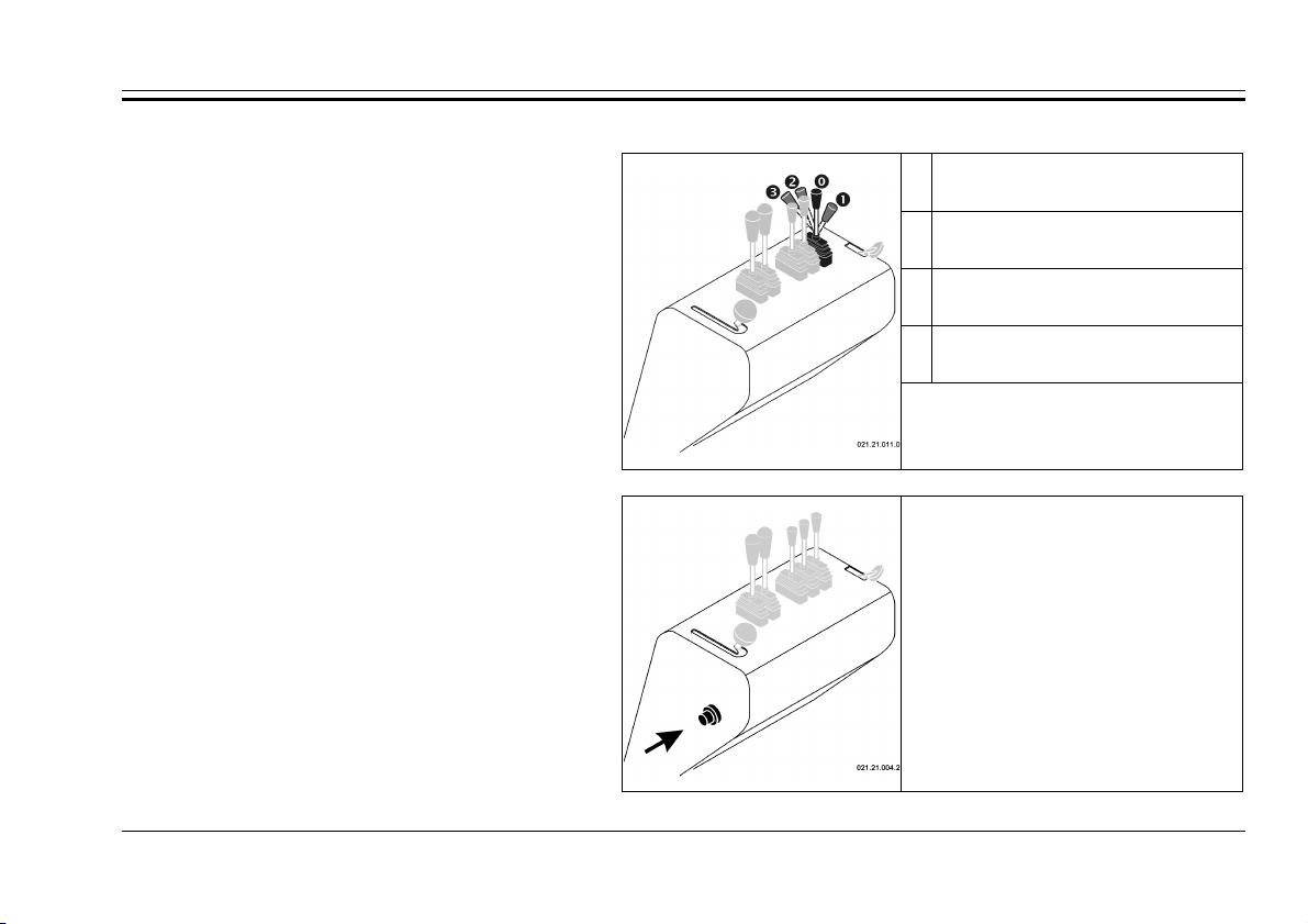
Command Lever for the Hydraulic Take-off
Command lever for the hydraulic force
Instrument
The hydraulic take-off instrument is composed
of two openings with rapid transmission of standard
type, indicated by the letters “A” and “B”, situated
on the right side of the dashboard.
Commands
UNSTABLE POSITION
Hydraulic pressure on “A”
STABLE POSITION
Resting position
POSIZIONE INSTABILE
Hydraulic pressure on “B”
The auxiliary command lever allows you to put
hydraulic oil pressure on the openings (cap. 3.11).
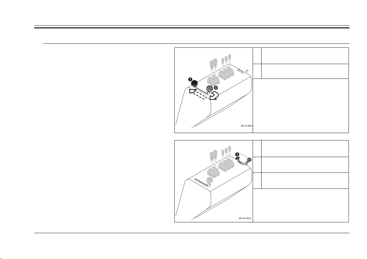
Command Lever for the Body
The command lever for the body activates the
hydraulic jack that activates the tipping of the body.
This position can only be used with the motor
turned on, while this position can also be used
when the motor is turned off.
fig. 19
instrument
UNSTABLE POSITION
The body overturns
STABLE POSITION
Resting position
UNSTABLE POSITION
Resting position
fig. 20
Command lever for the body
15
Series 65-80
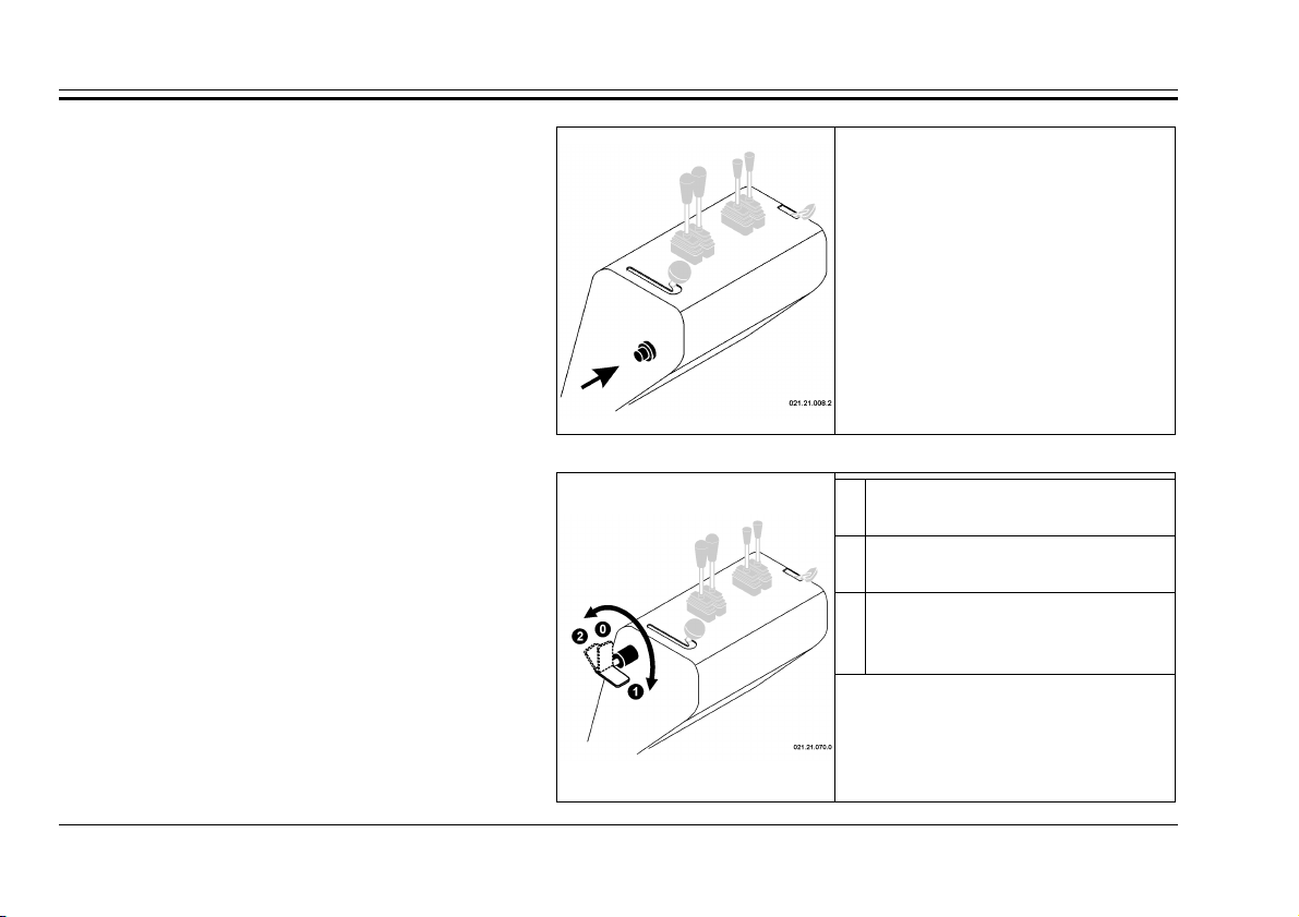
Horn Command
The horn button is on the left side of the
instrument panel. To sound the horn, push the
button. Only intermittent mode horn operation is
enabled. Continuous mode is not enabled.
The command works only with the engine
running.
Cut Off Battery Command
The device lever on the left side of the
dashboard controls the disconnection of the battery
from the electrical circuit of the machine.
Use the cut off battery to disconnect power from
the electrical circuit, particularly if the machine stop
to work, for a long period of time, can be removed
the lever to prevent the discharge of the battery.
fig. 21
Horn Command
STABLE POSITION
Battery connected
STABLE POSITION
Battery unplugged
STABLE POSITION
Battery unplugged,
it’s possible remove the lever
fig. 22
Cut Off Battery Command
16
2.2. A
STABLE POSITION
UTOLOADING VERSION
Parking Brake Command
Commands
STABLE POSITION
Deactivated brake
The command for the parking break, which
also serves as an emergency brake, allows one
to activate or deactivate the brake.
Accelerator Command
The command lever for the accelerator acts
upon the motor and allows one to vary the rotation
regimen in order to obtain the required power.
Activated brake
fig. 23
Command lever for the parking brake
POSIZIONE STABILE
Minimum regimen
POSIZIONE STABILE
…
Intermediate regimen
POSIZIONE STABILE
Maximum regimen
fig. 24
Accelerator Command
17

Series 65-80
Drive Levers
The drive levers control the rotation of the tracks through a hydraulic feed to the hydraulic motors.
The levers are active only when the motor is turned on.
UNSTABLE POSITION
Left Drive Lever
The left lever controls the left track.
The left track rotates forward
STABLEPOSITION
Resting position
UNSTABLE POSITION
The left track rotates backward
fig. 25
Left track command lever
UNSTABLE POSITION
Right drive lever
The right lever controls the right track.
The right track rotates forward
STABLE POSITION
Resting position
UNSTABLE POSITION
The left track rotates backward
fig. 26
Right track command lever
18

Command Lever for the Hydraulic Take-off
UNSTABLE POSITION
Instrument
The hydraulic take-off instrument is composed
of two openings with rapid transmission of standard
type, indicated by the letters “A” and “B”, situated
on the right side of the dashboard.
The auxiliary command lever allows you to
apply hydraulic oil pressure on the openings
(cap. 3.11).
Command Lever for the Body
The command lever for the body activates the
hydraulic jack that activates the tipping of the body.
Commands
UNSTABLE POSITION
Hydraulic pressure on “A”
STABLE POSITION
Resting position
UNSTABLE POSITION
Hydraulic pressure on “B”
fig. 27
Command lever for the hydraulic
take-off openings
UNSTABLE POSITION
The body overturns
STABLE POSITION
Resting position
turned on, while this position can also be used
when the motor is turned off.
This position can only be used with the motor
The body lowers
fig. 28
Command lever for the body
19

Series 65-80
Auto-loading Command Lever
The command lever for the auto-loading tool
works the hydraulic levers that provoke the raising
of the auto-loading bucket.
This command may only be used when the
motor is turned on.
STABLE POSITION
The bucket is free (floating)
UNSTABLE POSITION
Lowering of the bucket
STABLE POSITION
Resting position
UNSTABLE POSITION
Raising of the bucket
Horn Command
The horn button is on the left side of the
instrument panel. To sound the horn, push the
button. Only intermittent mode horn operation is
enabled. Continuous mode is not enabled.
The command works only with the engine
running.
20
fig. 29
Command lever for the body
fig. 30
Horn Command

Cut Off Battery Command
The device lever on the left side of the
dashboard controls the disconnection of the battery
from the electrical circuit of the machine.
Use the cut off battery to disconnect power from
the electrical circuit, particularly if the machine stop
to work, for a long period of time, can be removed
the lever to prevent the discharge of the battery.
Commands
STABLE POSITION
Battery connected
STABLE POSITION
Battery unplugged
STABLE POSITION
Battery unplugged,
it’s possible remove the lever
fig. 31
Cut Off Battery Command
21

Series 65-80
STABLE POSITION
2.3. A
UTOLOADING VERSION WITH SWIVEL BUCKET
Parking Brake Command
STABLE POSITION
Deactivated brake
The command for the parking break, which
also serves as an emergency brake, allows one
to activate or deactivate the brake.
Accelerator Command
The command lever of the accelerator works on
the motor and allows one to vary the rotation
regimen in order to obtain the required power.
22
Activated brake
fig. 32
Command lever for the parking brake
STABLE POSITION
Minimum regimen
STABLE POSITION
…
Intermediate regimen
STABLE POSITION
Maximum regimen
fig. 33
Accelerator command

Drive Levers
The drive levers control the rotation of the tracks through a hydraulic feed to the hydraulic motors.
The levers are active only when the motor is turned on.
UNSTABLE POSITION
Left Drive Lever
The left lever controls the left track.
The left track rotates forward
STABLE POSITION
Resting position
UNSTABLE POSITION
The left track rotates backward
Left track command lever
UNSTABLE POSITION
Right Drive Lever
The right lever controls the right track.
The right track rotates forward
POSIZIONE STABILE
Resting position
POSIZIONE INSTABILE
The left track rotates backward
Commands
fig. 34
fig. 35
Right track command lever
23
Series 65-80
UNSTABLE POSIT
ION
UNSTABLE POSITION
UNSTABLE POSITION
Command Lever for the Swivel Bucket
The swivel bucket command lever works the
hydraulic jack that provokes the rotation of the
bucket of the auto-loading tool.
The command may only be used when the
motor is on.
The bucket turns towards the
anterior side of the machine
STABLE POSITION
Resting Position
Provokes the rotation of the
bucket towards the operator
Command Lever for the Body
The command lever for the body activates the
hydraulic jack that activates the tipping of the body.
This position can only be used with the motor
turned on, while this position can also be used
when the motor is turned off.
24
Fig. 36
Swivel bucket command lever
UNSTABLE POSITION
The body overturns
STABLE POSITION
Resting position
The body lowers
fig. 37
Command lever for the body
Auto-loading Command Lever
The command lever for the auto-loading tool
works the hydraulic jack that provokes the raising
of the auto-loading bucket.
This command may only be used when the
motor is turned on.
Horn Command
The horn button is on the left side of the
instrument panel. To sound the horn, push the
button. Only intermittent mode horn operation is
enabled. Continuous mode is not enabled.
The command works only with the engine
running.
Commands
STABLE POSITION
The bucket is free (floating)
UNSTABLE POSITION
Lowering of the bucket
POSIZIONE STABILE
Resting position
POSIZIONE INSTABILE
Raising of the bucket
fig. 38
Command lever for the body
fig. 39
Horn Command
25

Series 65-80
Cut Off Battery Command
The device lever on the left side of the
dashboard controls the disconnection of the battery
from the electrical circuit of the machine.
Use the cut off battery to disconnect power from
the electrical circuit, particularly if the machine stop
to work, for a long period of time, can be removed
the lever to prevent the discharge of the battery.
STABLE POSITION
Battery connected
STABLE POSITION
Battery unplugged
STABLE POSITION
Battery unplugged,
it’s possible remove the lever
fig. 40
Cut Off Battery Command
26
Commands
STABLE POSITION
2.4. “HI-TIP” V
ERSION
Parking Brake Command
The command for the parking break, which
also serves as an emergency brake, allows one
to activate or deactivate the brake.
Accelerator Command
The command lever of the accelerator acts
upon the motor and allows one to vary the rotation
regimen in order to obtain the required power.
STABLE POSITION
Deactivated brake
Activated brake
fig. 41
Command lever for the parking brake
STABLE POSITION
Minimum regimen
STABLE POSITION
…
Intermediate regimen
POSIZIONE STABILE
Maximum regimen
fig. 42
Accelerator command
27
Series 65-80
UNSTABLE POSITION
UNSTABLE POSITION
Drive Levers
The drive levers control the rotation of the tracks through a hydraulic feed to the hydraulic motors.
The levers are active only when the motor is turned on.
UNSTABLE POSITION
Left Drive Lever
The left lever controls the left track.
The left track rotates forward
STABLE POSITION
Resting position
The left track rotates backward
fig. 43
Left track command lever
UNSTABLE POSITION
Right Drive Lever
The right lever controls the right track.
The right track rotates forward
STABLE POSITION
Resting position
The left track rotates backward
28
fig. 44
Right track command lever
“Hi-Tip” (High Unloading) Command Lever
UNSTABLE POSITION
UNSTABLE POSITION
The command lever the “Hi-Tip” works the
hydraulic jack that provokes the raising of the
anchoring structure of the body to consent the
unloading in containers or tubs with a high border.
The command may be used only when the
motor is on.
Commands
UNSTABLE POSITION
Allows the body to be raised
STABLE POSITION
Resting position
Provokes the lowering of the
body
Command Lever for the Body
hydraulic jack that activates the tipping of the body.
turned on, while this position can also be used
when the motor is turned off.
The command lever for the body activates the
This position can only be used with the motor
fig. 45
“Hi-Tip” Command Lever
UNSTABLE POSITION
The body overturns
STABLE POSITION
Resting position
The body lowers
fig. 46
Command lever for the body
29

Series 65-80
Auto-loading Command lever
The command lever for the auto-loading tool
works the hydraulic jack that provokes the raising
of the auto-loading bucket.
This command may only be used when the
motor is turned on.
Horn Command
The horn button is on the left side of the
instrument panel. To sound the horn, push the
button. Only intermittent mode horn operation is
enabled. Continuous mode is not enabled.
The command works only with the engine
running.
STABLE POSITION
The bucket is free (floating)
UNSTABLE POSITION
Lowering of the bucket
STABLE POSITION
Resting position
UNSTABLE POSITION
Raising of the bucket
fig. 47
Command lever for the body
fig. 48
Horn Command
30

Cut Off Battery Command
The device lever on the left side of the
dashboard controls the disconnection of the battery
from the electrical circuit of the machine.
Use the cut off battery to disconnect power from
the electrical circuit, particularly if the machine stop
to work, for a long period of time, can be removed
the lever to prevent the discharge of the battery.
Commands
STABLE POSITION
Battery connected
STABLE POSITION
Battery unplugged
STABLE POSITION
Battery unplugged,
it’s possible remove the lever
fig. 49
Cut Off Battery Command
31

Series 65-80
efore using the
machine you must read all of the instructions
in this manual and the user’s and
maintenance manual of the motor installed on
your machine scrupulously. Furthermore,
Read the user’s manual
and the maintenance manual for the motor
installed in your machine carefully and follow
the instructions prescribed for its own break
3. INSTRUCTION FOR USE
3.1. F
IRST USE
READ CAREFULLY: B
always keep it attached to the machine.
fig. 50 – Container
for manuals
32
The owner' s
manual and mai ntenance, together
with th e m anual of
the engine of the
mac hine, must be
al ways easily a vailable and should be
kep t in the dedica ted
co ntaine r fix ed on
the machine (se e the
fi g . 50).
The machine is normally delivered completely
assembled and ready for use with an empty fuel tank.
Fill the fuel tank, open the fuel tap and follow the start-
up procedure described in the appropriate paragraph.
3.2. B
REAKING-IN PERIOD
The technology used during the construction of your
machine does not require a break in period. However,
during the first period of use, it is necessary to use these
precautions:
During the first 50 hours, avoid using the motor at over
70 % of the total power.
READ CAREFULLY:
in period.
After the first 20 hours of operation, check the level of
the hydraulic oil in the tanks.

Instruction for use
WARNING: Before turning on the motor,
always insert the parking brake to avoid
uld
DANGER: Refuelling must always be done
le
refuelling or while handling fuel to avoid the
t up the motor only after
having made certain that there are no traces
During the first period of use, the tracks undergo an
adjustment, for which it is necessary, after the first 50
hours of operation, to carry out the regulation of the
tension of the tracks.
3.3. M
OTOR START-UP
Every time you wish to start up the motor, always
verify the following indications scrupulously:
•
Always start up the motor outside and be certain that
there are no other persons in the vicinity of the
machine and/or other impediments.
•
Check that there is fuel in the tank and, if necessary,
add some.
•
Always insert the parking brake.
eventual movement of the machine that co
present safety issues for the operator.
•
Follow the specific procedure prescribed by the
constructor of the motor shown in the attached
instructions.
When the motor is hot, in petrol operated motors,
avoid inserting the starter.
In diesel engines, can be an automatic valve that
helps to raise the start, it works automatically in the
first seconds of starting the engine.
3.4. R
EFUELLING
with the motor turned off! Do not smoke whi
risk of fire!
Refuelling and /or movement of the fuel from one
container to another must always be done outside,
always from fires or from other heat sources. Always
check that the type of fuel is the correct one, specified for
the motor of your machine.
•
Position the machine on a clean surface.
•
Unscrew the plug slowly.
•
Pour the fuel into the tank slowly.
•
Screw the plug on again tightly. Immediately dry any
fuel leakage.
WARNING: Star
of fuel that have accidentally spilled out!
33

Series 65-80
WARNING: The conservation of the fuel must
always be done with respect for the specific
from sources of
heat, and with clean, well closed suitable
REQUIRED: Avoid the dispersion of fuel
and/or fuel containers in the environment.
Carry out the disposal according to the
ect for the
DANGER: Always avoid overloading the
machine above the prescribed limits: during
movement, an overload could create
variations that were not foreseen
and could provoke the overturning of the
WARNING: Where possible, try to avoid
travelling on rocky or icy terrain, on rails and
may damage
the tracks and reduce their longevity. Also
avoid passing over material that could ruin the
tracks, such as sharp objects, pieces of metal,
etc. that could get caught up in the tracks and
provoke a break.
laws, in suitable places, away
containers!
current laws and with resp
environment.
3.5. D
RIVING THE MACHINE
structural
machine with serious safety consequences.
railway sections because they
At the start-up, regulate the number of rotations of the
engine to the desired level by activating the accelerator
lever, according to the required power (when the machine
is loaded, you must bring the lever above the halfway
mark between the minimum and maximum).
Under some conditions, especially when the machine
is loaded or going uphill, a loss of engine power may
occur because of a motor overload; this may also cause
it to shut down. In this case, slowly release the drive
command lever, regulating the speed to a level that does
not provoke an overload of the propeller.
Your machine is equipped with a hydrostatic
transmission, so, it is not necessary that the
rotations of the engine be at maximum for the
displacement. Leave the engine operating at its
maximum number of rotations does not improve the
functioning of the machine, rather, it certainly (and
uselessly) increases its fuel consumption: it is
advisable, therefore, to increase the rotations of the
engine only where it is absolutely necessary (to
proceed at maximum speed, to address steep slopes
with a full load, etc.).
34

Instruction for use
Never drive with the footrest unblocked:
always verify that the footrest is blocked and that
When you open or close the
you may
DANGER: When the machine is in gear, the
operator must always maintain the prescribed
3.5.1. D
RIVING POSITION
During the driving of the machine and during the work,
is necessary utilize the footrest platform in open position,
always (see fig. 51), to prevent risks.
Close the footrest platform only after use..
To use this footrest
you must position it in the
correct way:
•
Take out the safety
pin which blocks the
footrest;
•
Rotate the footrest to
a horizontal position;
•
Block the footrest
again by positioning
the safety pin again.
fig. 51 –Driving position
DANGER –
the safety pin is positioned correctly.
WARNING –
footrest, be careful with your hands:
cut yourself or crush them.
When the machine is in gear, always grasp the
stronghold handle firmly with one hand and use the other
hand simultaneously to activate both drive levers.
Never release the handle to operate the command
levers with both hands.
driving position.
Never speed when working, rather proceed at a
speed adjusted to your walking speed, in this way you will
maintain a safe control over the commands.
3.5.2. F
ORWARD GEAR
To allow the machine to advance one must activate
both drive levers simultaneously by pushing them
forward.
Avoid addressing downhill slopes in forward gear,
refer to the paragraph: “Travelling on Slopes”.
3.5.3. R
EVERSE GEAR
To allow the machine to back up you must activate
both drive levers, pulling them back simultaneously.
Avoid addressing uphill slopes in reverse gear,
35

Series 65-80
DANGER: While in reverse gear, always
check to see that there are no obstacles
DANGER: Completely avoid working on
terrains that have lateral slopes of more
than 10° and longitudinal slopes of more
than 20° to avoid the possibility of
with serious consequences for
especially with a loaded machine, rather follow the
procedure described in the paragraph: “Travelling on
Slopes” .
and/or persons in the vicinity.
3.5.4. T
RAVELLING ON SLOPES
overturning
the safety of the operator.
fig. 52 – a) going uphill; b) going downhill
When addressing sloped segments, especially when
the machine is loaded, you must use this particular
driving technique (see fig. 52):
Always address the uphill slopes in forward gear;
Always address the downhill slopes in reverse gear.
On high slope ground is necessary to work with high
regimen of motor (as the slope) minimizing the opening of
drive levers (see fig. 44); otherwise could be verify
cavitation problems and missing the “engine-brake” effect
(the hydraulic motors are forced by the slope and they
function like a pump): if the machine increase the speed
“alone”, release the drive levers.
fig. 53 – Motor regimen going downhill
36

Instruction for use
DANGER: if the machine travelling on high
slope with minimum motor regimen and
maximum opening of drive levers, “engine
brake” effect is missing and the machine
out of control with
the possibility of serious consequences for
the safety of operator and the proximity
coud increase the speed
persons.
3.5.5. S
TOPPING MOVEMENT
To stop movement one must release the drive levers
for the tracks simultaneously.
3.5.6. M
OVEMENT IN CURVES
To allow the machine to turn one must release the
lever on the side to which one intends to turn:
To turn to the right, release the right-hand drive lever;
To turn to the left, release the left-hand drive lever.
The steering is determined by the slowing of the
speed of one track with respect to the other.
Consequently the speed and the degree of steering are
proportional to the intensity of the release and to the
pressure with which you apply to each lever
3.5.7. C
OUNTER-ROTATION
It is also possible to make the machine spin round,
carrying out a complete “counter-rotation” around its axis,
in order to carry out manoeuvres in small spaces.
To make a clockwise counter-
rotation (towards the direction
of the clock hands) you must
push the left-hand lever
forward and pull the righthand lever back;
fig. 54 – Clockwise counter-rotation
To make a counter-clockwise
counter-rotation (towards the
opposite direction of clock
hands) you must push the righthand lever forward and pull the
left-hand lever back.
fig. 55 – Counterclockwise counter-
rotation
Using the counter-rotation manoeuvre often reduces
the duration of the rubber tracks, especially if you do it
upon rough surfaces.
37

Series 65-80
WARNING: If you move away from the
machine and leave it unattended, always
ing brake and be sure that no
unauthorized persons may turn it on or move
it. In the models which are equipped with one,
up key and unplug
PROHIBITED: It is strictly prohibited to use
the parking brake while the machine is
moving to arrest movement of the machine
If, when trying to deactivate the
brake, the lever resists noticeably, avoid
forcing the mechanism in that the wheel may
block. Before deactivating the brake, move
l
you have obtained the unblocking of the
3.6. S
TOPPING AND PARKING
activate the park
an emergency stop when the operator may deem
necessary to have an instantaneous block of the machine
during worko.
always take out the startthe battery.
Before stopping the machine, it is preferable to
position yourself on a flat paved surface, or on a flat and
compact ground.
•
Using the accelerator lever, bring the motor down to
its minimum number of rotations.
•
Insert the parking brake.
•
Turn off the engine.
•
Close the gas tap (on the models that are equipped
with one).
3.7. U
SING THE PARKING BRAKE
The machine has a safety device nominated as the
“Parking Brake” which impedes the machine from
moving even if the towing commands are activated. This
device serves to impede the accidental movement of the
machine in the absence of its operator; it also serves as
38
unless in case of emergency.
To activate: Pull the lever lightly towards yourself
and move it to the left making it go out of its slot and then
let it go: the brake will insert itself automatically.
To deactivate: Pull the lever towards yourself
decisively and lightly and move it to the right hooking it
into the special slot to block it: the brake has been
deactivated.
WARNING –
the machine forward and backward a bit unti
device.
Emergency Brake: the parking brake serves also as
a brake in emergency situations. To carry out an
emergency brake, pull the lever towards yourself lightly,
Instruction for use
DANGER: In the case that you may have to
the emergency brake, consider that this
causes the drive mechanism to block
instantaneously and may cause a loss of
WARNING: After the emergency brake
intervention, have the integrity and the
the device verified: a
continued use of the machine with an
inefficient device could be dangerous for your
PROHIBITED: It is strictly prohibited to
city limits indicated in
move it towards the left making it come out of the slot and
let it go: the brake will insert itself automatically.
use
control of the machine.
working order of
own safety and that of others.
3.8. T
RANSPORTING LOADS
surpass the load capa
the table on page 11.
3.8.1. C
ONSTRUCTION BODY (DUMPER)
The machine is equipped with a “dumper” type body
to transport inert and solid materials, suitable mainly to be
used for construction work.
3.8.2. “F
ARMING” TYPE BODY
Upon request, your machine may be fitted, in place of
the “dumper” type body, with a body that has sides that
can be opened, and is suitable to transport farming
materials.
fig. 56 – Farming type body
The opening of the sides allows one to enlarge the
loading surface to be able to transport cumbersome
objects. To obtain a larger loading surface, work with one
side at a time as follows (see fig. 56):
•
Open two anterior hooks “C”, lower the anterior side
39
Series 65-80
Before unloading, be certain that
the terrain is flat, solid and compact. Carry
out the dumping manoeuvre slowly and
rward with the
CAUTION: During the unloading, if the body
hits up against an obstacle, avoid moving the
machine forward: this could damage the
junctions of the body!
strictly prohibited to travel
“D” and take it out;;
•
Loosen the two wheels “A” positioned under the
loading surface;
•
Take out the two supports “B” from their housings;
•
Open the posterior hook “E” and lower the left lateral
side “F” making coincide the notches of the supports
in the holes “G”;
•
Repeat the operation on the other side;
•
Be sure that the sides are blocked and position the
load so that it will not fall: if possible tied it.
3.9. U
3.9.1. O
NLOADING MATERIAL
VERTURNING OF THE BODY
WARNING -
uniformly. Do not move fo
machine during the dumping phase.
Your machine is equipped with a hydraulic dumping
device for the body which allows for the unloading of material.
To carry out the dumping manoeuvre:
•
Position yourself on a level, solid, and compact
surface or terrain;
•
If the machine is equipped with a farming body,
unblock the anterior side;
•
Push the lever forward to provoke the overturning of
the body and the unloading of the material;
•
Pull the lever back until the body has returned to
travelling position, and then release the lever.
PROHIBITED: It is
if the body is not in its resting position.
3.9.2. R
AISING THE BODY
(“HI-TIP”)
On request the machine may be equipped with a
hydraulic device to raise the body during the unloading to
allow for unloading in containers or tubs with high walls,
named “Hi-Tip”.
To unload material normally, use the lever for the
overturning of the body (as indicated in the preceding
paragraph).
To carry out a high unloading, proceed as follows:
•
Position yourself on a level surface or on a level, solid,
and compact terrain;
40
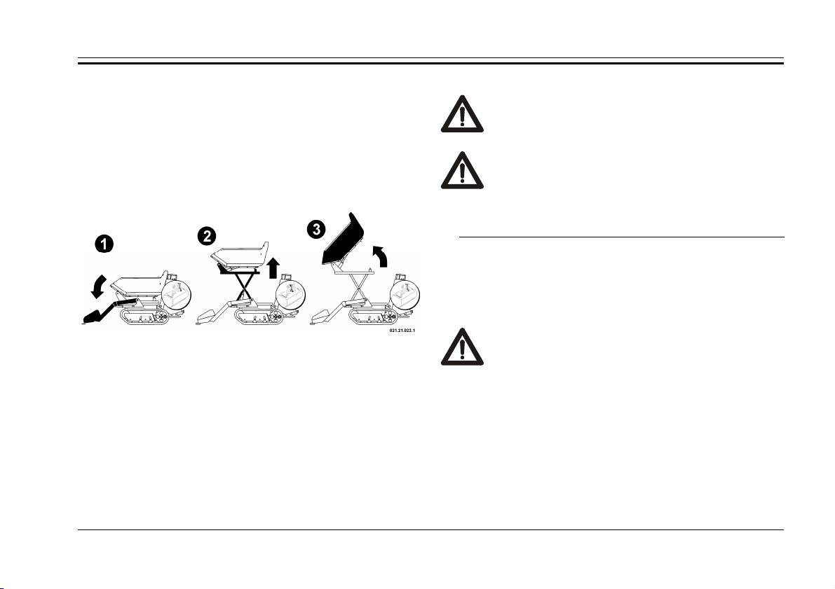
•
DANGER: Never carry out the raising of the
body without first stabilizing the machine with
DANGER: Never, for any reason, activate the
ou could provoke
-
loading device must remain raised above the
surface of the land to avoid collision with the
terrain and must be in a position that does not
Use the lever of the auto-loading device pushing it
forward to place the shovel on the ground in order to
stabilize the machine;
•
Raise the body to the desired height by pushing
forward the lever for raising;
•
Push the overturning lever for the body forward to
allow for the unloading of the material.
Instruction for use
the auto-loading shovel.
raising lever while driving. Y
the overturning of the machine
3.10. U
SE OF THE SELF-LOADING
Your machine may be equipped with an self-loading
mechanism consisting of an anterior bucket that has a
hydraulic command.
fig. 57 – Position for high unloading
To bring the body back to a driving position, proceed
as follows:
•
Pull back the overturning lever and bring the body
back to a horizontal position;
•
Release the command lever for the body
•
Pull the lever for raising the body backward until it has
reached the driving position;
•
Release the raising lever.
CAREFUL: During movement the auto
obstruct visibility.
Loading: To be able to load the body using the auto-
loading tool, you must follow this procedure:
•
advance the machine towards the pile of material
maintaining the benna in a horizontal position;
•
raise the shovel by pulling the lever towards yourself
until you have poured the contents into the body.
Repositioning: Push the lever forwards until the
41

Series 65-80
d movement
loading device must
READ CAREFULLY: Read the user’s
instructions carefully for all accessories
and/or tools that have been installed on
your machine. Always refer to the manual
which was provided with them and always
bucket has lowered to the correct height from the
ground.
Floating (auto-levelling): the auto-loading tool
may also be used to function as an auto-levelling
device, useful, for example for levelling ground. To
block the bucket in the floating position you must
push the auto-loading lever forward past the lowering
position until you have heard a click (the lever
remains in stable position).
CAREFUL: During the driving an
of the machine, the selfnot remain the the floating position.
3.11. S
UPPLEMENTARY HYDRAULIC COMMAND
Some versions may be equipped with a hydraulic
force instrument for the command of auxiliary
equipment.
The hydraulic force instrument is composed of two
openings with rapid transmission of standard type,
indicated by the letters “A” and “B”, situated on the right
side of the dashboard.
To obtain hydraulic oil pressure on the openings you
must work the auxiliary command lever.
To obtain pressure on the “A” opening, push the lever
forward.
To obtain pressure on the “B” opening, pull the lever
backward, toward yourself.
keep it attached to this manual.
3.12. A
Your machin e can
CCESSORIES
be equipped with
some addition a l
devices tha t mak e it
mor e complete.
To the side is
show n th e p o s it ion o f
the 12V DC po wer
out l e t (see fig. 5 8 )
that provi d e s power
fig. 58 - DC- out
for operation of
42

electrical devices with
WARNING: During transport, always position
elly to avoid the spilling of oil
additional features
highl ighted by the close
label (see fig. 59).
The label on the side
(fig. 60) shows the
electrical connection
dedicated to recharge the
electric battery of the
machine.
The electrical
recharging point outlet
is located on the right
side, near the lifting
point of the machine
(see fig. 61).
fig. 59
(cod. C0901.23.02)
fig. 60
(cod. C0902.23.02)
fig. 61
Richarging point
Instruction for use
3.13. T
RANSPORT
the machine lev
or other liquids .
If the machine needs to be transported, one must
proceed correctly to avoid dangers to persons and/or
to the machine, if there is any on the machine, keep
down completely the bucket during the transport.
Because of the weight of the machine, it is not
possible to move it manually. Thus, it is necessary to
use suitable means of lifting to load it onto a means
of transport.
The machine is equipped with 4 hooks for lifting
each one with a capacity of 7.000N (700kg) for a
total of 28.000N (2.800kg).
The position of each hook is
indicated with a label like the one
shown in the fig. 62 (C0900.13.66).
To do this operation safely you
should use, as tools of lifting, 4
ropes with hooks, CE compliant; the
two front ropes are 200cm of length,
and the two rear ropes are 170cm of
Lifting point
fig. 62
43

Series 65-80
WARNING: Raise the machine by hooking
it exclusively to the hooks predisposed for
this purpose: the anchoring of the
machine in other points can cause
ent fall of the
machine and can cause serious harm to
length, in the following way:
•
Disconnect the battery, turning the device to cut
off battery;
•
Empty the fuel tank and close the plug;
•
Fix the lifting hooks exclusively to the anchoring
points that were prescribed by the manufacturer
(fig. 63);
breakage with the consequ
persons.
fig. 63 – Anchoring points to lift the machine
44

Instruction for use
•
Fix it to the surface of the means of transport
pulling down firmly, with CE compliant ropes, and
always connecting to the points as indicated in the
figure 64.
fig. 64 – Anchoring points for transport
3.14. T
OWING
The machine is equipped with tow
hooks, located at the bottom of the
undercarriage, front abd rear (see fig.
66); if you need to tow the machine, to
take care of emptying the body.
Each anchor point for the
towing is evidenced by a label with
fig. 65
Towing point
the symbol shown in figure 65 and
can withstand a pull of 10.000N (1.000kg approx).
fig. 66 – Anchoring points for towing
45

Series 65-80
3.15. S
TORAGE
Whenever the machine must remain inactive for
several months, it is necessary to provide a correct
garaging so that the machine is in perfect working order
when it is used again.
In particular one must carry out storage by following
all of these instructions:
•
Carry out all necessary repairs;
•
Disconnect the battery, turning the device to cut off
battery;
•
Empty the fuel tank completely;
•
Proceed with a careful cleaning and remove all
mud, and/or organic residues carefully;
•
Proceed with all operations regarding the motor that
are described in its own manual;
•
Carry out a greasing of all points listed in the
specific chapter;
•
Place the machine in such a way that it is sheltered
from atmospheric agents under stable conditions
and on a flat surface;
•
If the machine is equipped with batteries, unplug
them and lubricate with the correct grease;
•
Periodically, every two months, recharge the
battery;
•
If the motor is equipped with a start-up key, take it
out and conserve in a safe place.
When putting the machine back into service:
•
carry out all greasing again in all prescribed points
found in the specific chapter;
•
If the machine is equipped with a battery, recharge
it and reconnect it being certain of the correct
polarity of the ends;
•
Insert the cut off battery lever;
•
Proceed with the operations concerning the motor
described in its own manual;
•
Check the oil level and add some if necessary.
46

4. MAINTENANCE
DANGER: always carry out all maintenance
operations with the motor off and with the
Maintenance and Adjustment Table
Maintenance
start up keys not inserted.
A good maintenance is necessary and is the secret to
obtaining low running costs, to lengthening the life of your
machine, and to always maintaining it at its highest
efficiency.
Beyond the normal maintenance operations on the
mechanic and hydraulic parts, it is a good rule to carry out
a periodic washing of the machine and to proceed with a
careful cleaning to take away all mud residues. After
every wash it is necessary to grease all of the parts that
are subject to friction, as specified in the paragraph
“Greasing”.
4.1. M
AINTENANCE INTERVALS
To maintain the highest level of efficiency, it is
necessary that the maintenance be carried out at regular
programmed intervals.
In the following table a summary of the maintenance
operations is listed that are to be carried out periodically.
Work
Frequency
Every 8 hours
Every 50
hours
Every 100 h. Parking Brake
Every 200 h. Motor wheel hubs
Every year
or 300 hours
(1)
Check with the attached manual for the motor
(2)
In dusty areas you must increase the frequency
Description
Machine
Drive Levers
Command Levers
Body
Auto-loading
“Hi-Tip” lift
Track rollers
(1)
Motor oil
Tracks
Hydraulic oil
Air filter
Hydraulic oil
Hydraulic services oil filter
Hydraulic drive oil filter
Dry air filters
Motor oil
(1)(2)
(1)
(1) (2)
Verify
Greasing
Cleaning
Adjustment
Substitution
47

Series 65-80
READ CAREFULLY: Carefully read the
instructions and the mode of use for the
REQUIRED: When changing the motor oil,
always use a suitable aspirator to remove old
Avoid the dispersion of oil and filters in the
environment and carry out their disposal with
respect for the environment and the
4.2. M
OTOR
motor found in the attached specific manual.
The machine that was delivered could be equipped at
the origin with different engine types for specific needs
and/or markets.
A correct maintenance is the best way to conserve the
motor of your machine so that it is always working at its
highest efficiency and this allows you to maintain low
operation costs.
For the maintenance of the motor, pay scrupulous
attention to the attached manual that was given to you.
oil.
regulations in force.
4.2.1. PRE-
FILTER AND AIR FILTER IN AN OIL BATH
Your machine can be equipped with a special air filter in
an oil bath, which increases and improves the filtration
capacity.
The maintenance
of pre-filter “P” (see
fig. 67), establish the
cleaning every 100
hours.
Unscrewing the
wing screw (see fig.
68), which blocks the
cover of pre-filter,
remove the section in
clear plastic “T”,
clean using a simple
washing with water
and then replace il.
For the maintenance of the filter in
an oil bath “F”, is
Pre-filter and Air Filter
fig. 67
necessary remove the engine hood.
After removing the hood, the air filter is easily
accessible.
48

Maintenance
Every 15 days, to check the oil level in the filter,
release the bottom cup of the filter (fig. 68), loosening
the hooks “G”.
Remove the cup of the air filter, being careful not
to spill the oil content, verify that oil reaches the
metal tab “L”, and if necessary, add the missing oil.
Replace the filter bowl.
fig. 68 – Pre-filter and Air Filter with oil bath
cartridge “C” and change the oil in the filter bowl cup.
To clean the cartridge is recommended to wash by
immersion in a vassel containing diesel or petrol to
remove the dirth.. To replace oil in the air filter,
remove all the oil in the cup and wash it with diesel or
petrol. Dry the cup and restore the right level of oil
wich reaches the metal tab “L” like described above
(fig. 68).
Verify
Every 15 days Check the level of the oil in the cup.
Substitution
Every 60 days
Substitute the oil in the cup and
clean the filter part.
For the verify and the substitution of the oil in the cup of
the air filter, utilize only synthetic oil 10W – 40W.
DANGER: do not throw the oil in the environment.
Carry out the disposal with respect for the environment
and the regulations in force.
Every 60 days, it is necessary to clean the filter
49

Series 65-80
REQUIRED: Avoid the dispersion of oil in the
environment and carry out the disposal with
respect for the environment and the
DANGER: The hydraulic oil can reach high
temperatures, especially after a day of work:
avoid substituting the oil when it is hot to
LY: The thermometer
installed in the machine is equipped with a
double scale and may be read in centigrade °C
and Farheneit °F according to the conventions
of the different countries. Be reminded that in
Italy measurement in °C is used: refer only to
4.3. H
4.3.1. H
YDRAULIC CIRCUIT
YDRAULIC OIL
regulations in force.
Your machine was provided with a specific
thermometer/signal to verify both the temperature and the
level of the hydraulic oil in the tanks, positioned on the
right side of the dashboard (see fig. 69).
Verifying Temperature
avoid the risk of burning yourself.
READ CAREFUL
this value.
The temperature of the hydraulic oil is verified by
reading the value on thermometer “B” (see fig. 69): the
temperature is considered regular when it does not
surpass 85°C.
Verifying Oil Level
Every 8 hrs
Check the level of hydraulic oil in the
tank.
To verify the correct hydraulic oil level, the
machine will be placed on a flat surface, with the body
closed and self-loading arm lowered to the ground, if
any.
The engine must be started for several minutes
(about 5 min.) So that the
oil has a temperature of
40 ° C.
The correct level is when
the oil reaches the bottom of
the line “D” (see fig. 69 “D”).
Restoring Oil Level
• Unscrew the top “A” on
the upper tank;
• Restore the level by
fig. 69 – Oil level
50

Maintenance
the emptying
when the motor is off and with the body
adding the oil specified into the opening “A”;
• Screw the top “A” back on sealing it properly, and turn
on the motor following the correct procedure;
• Briefly operate the drive levers and the command
levers;
• Stop the motor and check that the level of the oil “C”
reaches the red line “D” and, if necessary, repeat the
operation.
Substitution
Every 300 hrs
To substitute the hydraulic oil, use a suitable aspirator
and work when the oil is cool, verifying its temperature
using the thermometer.
DANGER: Always carry out
blocked with the special bar.
Empty the upper tank first;
• Unscrew the top “A” on the upper tank, removing the
washer “B”, and vacuum the oil using a suitable
Substitute the hydraulic oil in the
tank.
fig. 70 – Substitution of oil and filters
51

Series 65-80
lways carry out the emptying
operation of the lower tank when the motor is
turned off, and with the body blocked by the
DANGER: Always substitute the filters when
blocked
REQUIRED: Carry out the disposal of the oil
and filters with respect for the environment
aspirator.
DANGER: A
appropriate bar.
• Unscrew the top “C” on the lower tank and remove the
washer “D”;
• Move the terminal “E” and remove the top “F” with the
washers;
• Vacuum the oil completely using the suitable aspirator;
• When you have completed the operation, place the top
“F” and terminal “E” back on carefully;
• Screw the top “C” back on with its washer “D”;
• Fill the tank exclusively from the upper tank from the
opening of “A” until the red line is reached;
• Screw the top “A” back on with its washer “B” and turn
on the motor;
• Briefly operate the drive and command levers;
• Turn off the motor and check the level if necessary,
add more;
• After 8 hours of working, check the level again.
4.3.2. H
hydraulic oil circuit, positioned in the lower part of the
YDRAULIC OIL FILTER
Your machine is equipped with two filters on the
frame, under the body. One of the filters, which is an
immersion type, is screwed directly into the tank (see fig.
70 pos “G”), while the other one which is a cartridge type
(see fig. 70 pos “H”) is positioned near to the other.
the motor is shut off and the body is
by the appropriate bar.
and for the regulations in force.
Drive Circuit
Every 300 hrs
The filter in the circuit which feeds from the auxiliary
drive pump is a cartridge type and does not require any
type of cleaning operation, however must be substituted at
the prescribed intervals.
To substitute, carefully follow the described operations
(see fig 70):
• Empty the oil tanks, both the upper one and the
anterior one, by following the procedure in the
preceding paragraph;
• Using the appropriate key, unscrew the old filter “H”;
Replace the hydraulic drive circuit oil
filters.
52
• Lightly lubricate the washer of the new filter;
• Screw the new filter down well, clenching tightly by
hand only;
• Refill the oil level again.
Maintenance
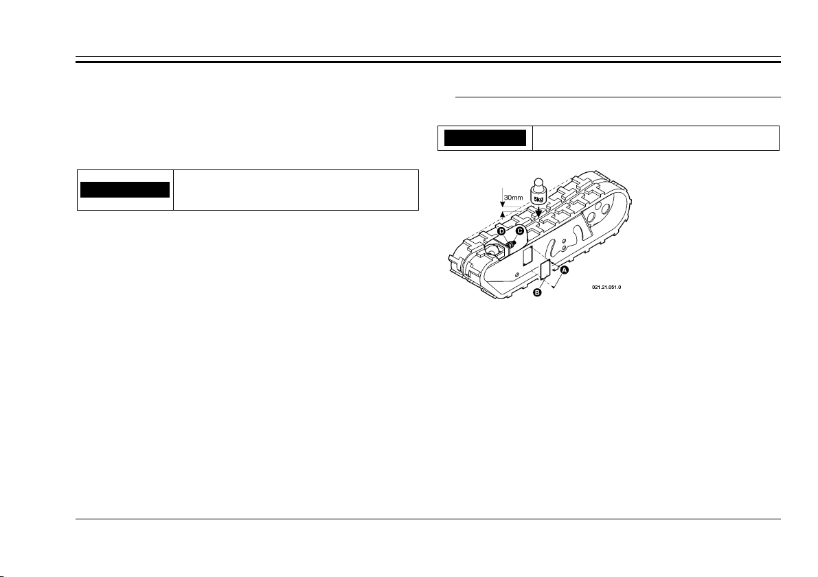
4.4. T
RACKS
Registration
Every 50 hrs Register the tension of the tracks.
Services Circuit
Every 300 hrs
Substitute the oil filter for the
services circuit.
The filter for the circuit feed of the auxiliary service
pump is an immersion type and is screwed directly to the
inferior tank.
Replacement:: to replace the filter, follow these
instructions (see fig. 70):
• Empty the oil tanks, both the upper and anterior ones
by following the correct procedure;
• Unscrew the oil tube “G” by working on the junction;
• Unscrew the filter and take it out of the tank;
• Put the nipple on the new filter always checking the
lining;
• Screw the filter back into the tank;
• Screw the oil tube back on;
• Fill the tanks and check the levels.
The correct tension of the tracks is
important in order to
guarantee their longevity and for your
own safety: to check
it, apply a pressure
of 5 kg on the track
and check that the
fig. 71-Regulation track tension
arrow is at about
30mm.
To carry out the regulation of the tension of the tracks
correctly:
• Take off the cover “B” by unscrewing the two screws “A”;
• Using two wrenches, loosen the counter-nut “C”;
• Regulate the tension by working on nut “D”;
• Check that the arrow is at 30 mm;
• When you have finished regulating, block the counter-
nut;
• Put the cover back on;
• Repeat the same procedure on the other track.
53

Series 65-80
DANGER: Never work with the machine
raised on a jack or suspended, rather always
place it upon suitable trestles that can
maintain the weight of the machine before
Substitution
starting work.
For the substitution
of the tracks, proceed
as follows:
• Raise the side of
the machine on
which you wish to
work using
hydraulic jacks or a
crane;
• Position the
machine on
suitable trestles, and check to see that it is stable;
• Take off the cover “B” by unscrewing the screws “A”;
• Using two wrenches, loosen the counter-nut “C” and
completely unscrew both the counter-nut and nut “D”;
• Take off the track “E” starting from the anterior part;
• Mount the new track lining it up with the teeth in the
drive wheel “F”;
• Fit in the anterior part of the track onto the neutral
fig. 72 – Substitution of tracks
wheel “G”;
• Register the tension by working on nut “D”;
• Check that the arrow is at 30mm;
• When the registering is done, block the counter-nut
“C”;
• Put the cover back on.
4.5. P
ARKING BRAKE
Registering
A correct registering of
the parking brake is
obtained when, the brake is
deactivated with the lever
“A” in position , and the
cursor “E” is 10mm from the
hub wheel “F”.
To register, proceed as
follows:
• Unscrew the nut “B”
from the register “C”;
• Regulate the tension of
the cable “D” by working
on the register “C”;
• Verify the correct posi-
fig. 73 – Regulation
of parking brake
54

Maintenance
tion of the cursor “E”;
• Tighten the nut “B”;
4.6. G
REASING
Every 8 hrs
Refurnish the grease in all
prescribed points.
fig. 74 – Greasing points
Refurnish the grease in all prescribed greasing points,
using a suitable grease.
Grease the drive levers using a spray type lubricant.
Hub Wheel
Every 200 hrs Greasing the hubs of the wheels.
Periodically it is
also necessary to
refurnish the grease on
the hubs of the drive
wheels, a procedure
that is done as follows,
always working on
fig. 75 –Greasing of wheel hub
one side at a time:
• Completely unscrew and take out screw “A” and the
washer “B” that block the drive wheel “C”;
• Completely fill the cavity with grease;
• Screw back screw “A” always checking the washer;
• Repeat the procedure on the wheel on the other side.
55

Series 65-80
4.7. R
ECOMMENDED LUBRICANTS
Motor Oil
Hydraulic Oil
Grease
56
Type Quantity
15W40
AT FII 16 l
MR
thick fluid

5. INCONVENIENCES AND BREAKDOWNS
Inconvenience Causes Remedy
Excessive oil level. Correct the oil level
Hydraulic oil is leaking.
Overheated oil. Turn off the machine and let it cool down
Breakdown in the hydraulic circuits.
Excessive oil level. Correct the oil level
Oil leak.
Breakdown in hydraulic circuits or in
washers.
The hydraulic commands do not
respond correctly.
The body or the arms of the bucket
moves slowly.
Insufficient oil level. Refill to the correct level
Breakdown in the hydraulic circuits.
Overheating of the oil. Interrupt work and let it cool down
The motor does not have power.
Insufficient oil level. Refill to the correct level
Lack of pressure in the auxiliary
hydraulic openings.
Eccessive oil temperature.
Sleeves not correctly inserted. Insert the sleeves correctly
Breakdown in the hydraulic circuits.
Insufficient oil level. Refill to the correct level
Overheating. Interrupt work and let cool down
The brake cable is broken. Have the cable substituted by a mechanic
Parking brake does not deactivate.
The brake is blocked.
Inconveniences and breakdowns
Have the machine looked at by a mechanic with
specific competence
Have the machine looked at by a mechanic with
specific competence
Have the machine looked at by a mechanic with
specific competence
Have the machine looked at by a mechanic with
specific competence
Have the machine looked at by a mechanic with
specific competence
Move the machine slightly forward and backward
and try again
57

Series 65-80
Inconvenience Causes Remedy
The parking brake is activated. Deactivate the parking brake
Not enough oil in the hydraulic circuit. Restore oil to the correct level
The machine does not move.
The tracks are broken. Replace the tracks
Breakdown in the hydraulic
components.
Have the motor looked at by a mechanic with this
specific competence
Incorrect track tension. Register the tension.
Excessive noise from the tracks during
movement.
Excessive noise from the body or from
the arms of the bucket.
Broken or worn tracks. Replace the tracks.
Broken rollers or ball bearings.
Have the motor looked at by a mechanic with this
specific competence
Needs greasing.. Greasing
Broken rollers. Have the machine repaired by a mechanic
The accelerator does not respond. Il cavo dell’acceleratore è rotto. Fate sostituire il cavo da un’officina meccanica
The motor does not work correctly or
makes an excessive amount of noise.
Various causes.
Have the motor looked at by a mechanic with this
specific competence
The air filter is blocked. Replace the air filter.
The motor does not develop power.
Various causes.
Have the motor looked at by a mechanic with this
specific competence
Not enough fuel. Refuel the machine
The motor does not start.
The start-up procedure was not carried
out correctly.
Follow the correct start-up procedure
The battery is dead. Have the battery recharged or replace it
58

6. INDEX
Accelerator
Command Lever 13
Command Lever- 17
Command Lever- 22
Command Lever- 27
Registration See Attached
Accessories 7; 42
Air Filter
Cleaning See Attached
Substitution See Attached
Arm
Blocking the 6
Auto-loading, Command Lever- 20; 25; 30
Auto-loading, Use of the - 41
Blocking the Arm 6
Blocking the Body 5
Blocking the Footrest 6
Blocking the Lift 6
Body
Blocking the 5
Command Lever- 15; 19; 24; 29
Construction (Dumper) 39
Farming Type 39
Overturning of the - 40
Raising (Hi-Tip) 40
Brake
Command Lever 13; 17; 22; 27
of Emergency 38
of Emergency, Using 38
of Parking 38
of Parking, Registering 54
of Parking, Mainutenance 54
of Parking, Using 38
breakdown, Inconveniences and - 57
Breaking-in Period 32
Cleaning Air Filter See Attached
Command
Accelerator Lever 13; 17; 22; 27
Auto-loading Lever 20; 25; 30
Body Lever 29
Drive Lever 14; 18; 23; 28
High Unloading Lever 29
Hi-Tip Lever 29
Lever for the Body 15; 19; 24
Lever for the Hydraulic Take-off Instrument
15; 19
Lever for the Swivel Bucket 24
Parking Brake Command 13
Parking Brake Lever 17; 22; 27
Supplementary Hydraulic 42
Commands 13
Autoloading Version 17; 22
Hi-Tip Version 27
Hydraulic Overturning Version 13
Conter-rotation 37
Curves, Movement in - 37
Cut Off Battery
Command 16; 21; 26; 31
Cut Off Battery Command 16; 21; 26; 31
Dimensions 11
Index
Drive
Levers of - 14; 18; 23; 28
Driving
the Machine 34
Driving
Position 35
Dumper, Construction Body 39
Emergency, Brake of - 38
Farming, Type Body - 39
First Use 32
Footrest
Blocking the 6
Forward, Gear - 35
Gear
Forward 35
Reverse 35
general information 1
Goal of the Manual 1
Greasing
Hub Wheel 55
Points of - 55
High Unloading, Command Lever 29
Hi-Tip
Command Lever- 29
Raising the Body 40
Horn
Comnd 16; 20; 25; 30
Horn Command 16; 20; 25; 30
Hub Wheel, Greasing 55
Hydraulic
59

Series 65-80
Circuit -, Maintenance 50
Supplementary - Command 42
Hydraulic Oil 50
Restoring Level 50
Substitution 51
Verifying Level 50
Verifying Temperature 50
Hydraulic Take-off Instrument
Command Lever- 15; 19
Identification Plate 5
Inconveniences and breakdown 57
Instruction for use 32
Introduction 2
Level
Hydraulic Oil 50
Motor Oil See Attached
Lever
Accelerator Command 13
Command of Auto-loading 20
Command of the Body 15
of Accelerator Command 17; 22
of Auto-loading Command 25; 30
of Body Command 29
of Command for the Body 24
of Command for the Hydraulic Take-off
Instrument 15
of Command for the Hydraulic Take-off
Instrument 19
of Command for the Swivel Bucket 24
of Command for thye Body 19
of Drive 14; 18; 23; 28
of High Unloading Command 29
of Hi-Tip Command 29
of Parking Brake Command 17; 22; 27
Parking Brake Command 13
Leverof Accelerator Command 27
Lift
Blocking the 6
Livello
Olio Idraulico 49
Machine
Description of the - 2
Driving the - 34
Identification of the – 5
Machine and Manufacturer Identification 5
Machine Description 2
Maintenance 47
Maintenance, Intervals of - 47
Manual, Goal of the - 1
Manufacturer, Identification of - 5
Minimum, Regimen Registration See Attached
Motor
Maintenance 48; See Attached
Start-up of - 33
Motor Oil
Substitution See Attached
Verify Level See Attached
Motor Start-up 33
Movement
in Curves 37
Stopping of - 37
Oil Filter
Hydraulic 52
Replacement - Services 53
Substitution - Drive 52
Substitution of Services Filter 53
Olio Idraulico 48
Sostituzione 49
Verifica Livello 49
Other Tags 10
Overturning of the Body 40
Parking
Brake of - 38
Brake of -, Maintenance 54
Stopping and - 38
Pendenze
Ammissibili 11
Raising the Body (Hi-Tip) 40
Recommended Lubricants 56
Refuelling 33
Registering
Parking Brake 54
Registration
Accelerator See Attached
Minimum See Attached
Tracks 53
Replacement
Services Oil Filter 53
Restore
Hydraulic Oil Level 50
Restoring
Level Motor Oil See Attached
Reverse, Gear - 35
Safety
Devices of - 5
Information about - 3
Tags - 7
Safety Devices 5
Safety information 3
Safety Tag
Crushing 9
Cutting 9
60

Fan 8
Hot Surface 8
Maximum Slopes 10
Overturning 9
Safety Distance 8
Safety Tags 7
Caution 9
Self-loading 41
Slopes
Travelling on - 36
Sostituzione
Olio Idraulico 49
Stopping
and Parking 38
of Movement 37
Storage 46
Substitution
Air Filter See Attached
Drive Oil Filter 52
Hydraulic Oil 51
Motor Oil See Attached
Services Oil Filter 53
Tracks 54
Swivel Bucket, Command Lever- 24
Targhetta di Sicurezza
Marcia sulle Pendenze 43
Technical Data 12
Towing 45
Tracks 53
Registration 53
Substitution 54
Transport 43
Travelling
on Slopes 36
Unloading Material 40
Use
Instruction for - 32
of the Auto-loading 41
Using
Emergency Brake 38
of Parking Brake 38
Verifica
Livello Olio Idraulico 49
Verify
Hydraulic Oil Level 50
Hydraulic Oil Temperature 50
Motor Oil Level See Attached
Warranty 1
61

Series 65-80
7. SUMMARY
Introduction ................................................................. 2
1. General Information .............................................. 1
1.1. Warranty ......................................................... 1
1.2. Goal of the Manual.......................................... 1
1.3. Machine Description ....................................... 2
1.4. Safety Information .......................................... 3
1.5. Machine and Manufacturer Identification ....... 5
1.6. Safety Devices ................................................. 5
1.6.1. Blocking the Body ..................................... 5
1.6.2. Blocking the Arm ....................................... 6
1.6.3. Blocking the Footrest ................................. 6
1.6.4. Blocking the Lift (“Hi-Tip”) ...................... 6
1.7. Accessories...................................................... 7
1.8. Safety Tags ...................................................... 7
1.8.1. Safety Distance .......................................... 8
1.8.2. Hot Surface ................................................ 8
1.8.3. Fan ............................................................. 8
1.8.4. Crushing ..................................................... 9
1.8.5. Cutting........................................................ 9
1.8.6. Procedure for Caution ................................ 9
1.8.7. Overturning ................................................ 9
1.8.8. Maximum Slopes ..................................... 10
1.8.9. Procedure for Addressing Slopes ............. 10
1.8.10. Other Tags .......................................... 10
Admissible Slopes ................................................. 11
1.9. Dimensions ................................................... 11
1.10. Technical Data .............................................. 12
2. Commands .......................................................... 13
2.1. Hydraulic Overturning Version .................... 13
2.2. Autoloading Version ..................................... 17
2.3. Autoloading Version with Swivel Bucket .... 22
2.4. “Hi-Tip” Version .......................................... 27
3. Instruction for use ............................................... 32
3.1. First Use ........................................................ 32
3.2. Breaking-in Period ........................................ 32
3.3. Motor Start-up .............................................. 33
3.4. Refuelling ..................................................... 33
3.5. Driving the Machine ..................................... 34
3.5.1. Driving Position ....................................... 35
3.5.2. Forward Gear ........................................... 35
3.5.3. Reverse Gear ............................................ 35
3.5.4. Travelling on Slopes ................................ 36
3.5.5. Stopping Movement ................................. 37
3.5.6. Movement in Curves ................................ 37
3.5.7. Counter-rotation ....................................... 37
3.6. Stopping and Parking .................................... 38
3.7. Using the Parking Brake ............................... 38
3.8. Transporting Loads ....................................... 39
62

Summary
3.8.1. Construction Body (Dumper) .................. 39
3.8.2. “Farming” Type Body ............................. 39
3.9. Unloading Material ....................................... 40
3.9.1. Overturning of the Body .......................... 40
3.9.2. Raising the Body (“Hi-Tip”) .................... 40
3.10. Use of the Self-loading ................................. 41
3.11. Supplementary Hydraulic Command ............ 42
3.12. Accessories ................................................... 42
3.13. Transport ....................................................... 43
3.14. Towing .......................................................... 45
3.15. Storage .......................................................... 46
4. Maintenance ........................................................ 47
4.1. Maintenance Intervals ................................... 47
4.2. Motor ............................................................ 48
4.2.1. Pre-filter and Air Filter in an oil bath ...... 48
4.3. Hydraulic Circuit .......................................... 50
4.3.1. Hydraulic Oil ........................................... 50
4.3.2. Hydraulic Oil Filter .................................. 52
4.4. Tracks ........................................................... 53
4.5. Parking Brake ............................................... 54
4.6. Greasing ........................................................ 55
4.7. Recommended Lubricants ............................ 56
5. Inconveniences and breakdowns ......................... 57
6. Index ................................................................... 59
7. Summary ............................................................. 62
63

Series 65-80
64
 Loading...