

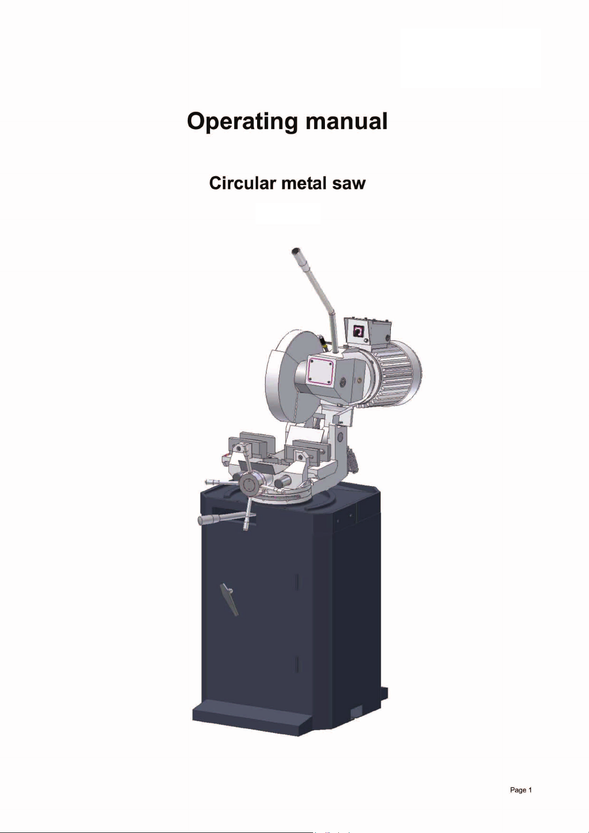
CS350

Table of Contents
1 Safety
1.1 Safety warnings (warning notes)..............................................................................4
1.2 Proper user............................................................................................................... 6
1.3 Possible dangers caused by the circular metal saw................................................. 6
1.4 Qualification of personnel............ ... .... ... ... ... .... ... ... ... ................................................7
1.5 User positions. ... .... ... ... ....................................... ... ... ... ....................................... ... ... 8
1.6 Safety devices.......................................................................................................... 8
1.7 Individual protection gear ............... ....................................... ... .... ... ... ... ... .... ... ... ... . 10
1.8 Safety during operation ..........................................................................................11
1.9 Safety during maintenance.....................................................................................12
1.10 Accident report .......................................................................................................12
1.11 Electrical system................................. ... ... ....................................... ... ... ... .... ... .......13
1.1.1 Classification of hazards ................ ... .... ... ... ... ... .... ...................................... ... 4
1.1.2 Other pictograms............................................................................................5
1.4.1 Target group................................................................................................... 7
1.4.2 Authorised personnel .................. ... ... ....................................... ... ... .... ... ... ......7
1.6.1 Prohibition, warning and mandatory labels .................................................. 10
1.9.1 Disconnecting the circular metal saw and making it safe............................. 12
1.9.2 Using lifting equipment.................................................................................12
1.9.3 Mechanical maintenance work.....................................................................12
2 Technical data
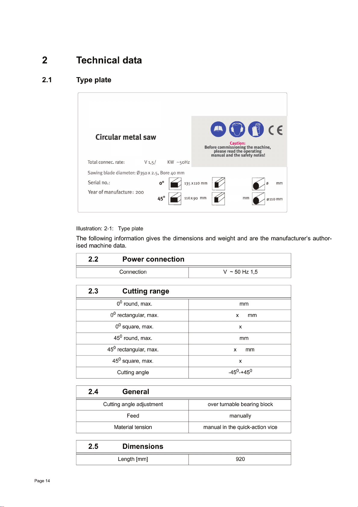
2.1 Type plate............................................................................................................... 14
2.2 Power connection...................................................................................................14
2.3 Cutting range............ ... ... ... .... ...................................... .... ... ... ... .... .......................... 14
2.4 General................................................................................................................... 14
2.5 Dimensions............................................................................................................. 14
2.6 Speed of saw blade................................................................................................15
2.7 Environmental conditions ............ ... .... ... ... ... ....................................... ... ... .... ... ... ... . 15
2.8 Operating material............. .... ... ... ... .... .................................................................... 15
2.9 Emissions............................................................................................................... 15
3 Assembly
3.1 Extent of supply......................................................................................................16
3.2 Storage................................................................................................................... 16
3.3 Installation and assembly.......................................................................................16
3.3.1 Requirements of the installation site ............................................................16
3.3.2 Fasten the substructure of the circular metal saw on the floor....... .... ... ... ... . 17
3.3.3 Mount the saw on the machine substructure................................................18
3.3.4 Mount the lever arm ..................................................................................... 18
3.3.5 Mount the saw blade....................................................................................18
3.4 First use..................................................................................................................19
3.4.1 Checking ......................................................................................................19
3.4.2 Direction of the saw teeth..... .... ... ... ... .... ... ... ... ... .... ... ... ................................. 19
3.4.3 Check the oil level in the worm gear ............................................................19
3.4.4 Fill in coolant ................................................................................................20
3.4.5 Power supply..... ... ... .... ... ... ... .... ...................................... .... ... ... ... ... .... ..........20
3.4.6 Check the running direction of the saw blade .............................................. 20
Page 2
4 Operation
4.1 Safety ..................................................................................................................... 21

4.2 Control and indicating elements ............................................................................. 21
4.
3 Insert workpiece ..................................................................................................... 22
4 Saw blade speed.................................................................................................... 23
4.
4.4.
1 Speed change.............................................................................................. 23
4.4.2 Select the toothing and the shape of the tooth ............................................ 23
4.
5 Switching on the machine ...................................................................................... 25
4.
6 Switching off the machine ...................................................................................... 25
7 Sawing of angles.................................................................................................... 26
4.
4.
8 Cooling ................................................................................................................... 27
5 Maintenance
5.1 Safety ..................................................................................................................... 29
5.1.
1 Preparation .................................................................................................. 29
5.1.
2 Restarting..................................................................................................... 29
2 Inspection and maintenance .................................................................................. 30
5.
5.
3 Mounting and replacing the saw blade................................................................... 32
5.3.
1 Dimensions of sawing flange ....................................................................... 33
5.
4 Repair..................................................................................................................... 33
6 Ersatzteile - Spare parts - CS350
6.1 Ersatzteilzeichnung - Explosion drawing................................................................ 34
6.1.
1 Einzelteile - Spare parts - CS350................................................................. .35
2 Schaltplan - Wiring diagram - CS350....................................................................... 37
6.
6.2.
1 Ersatzteilliste - Spare parts list - CS350......................................................... 38
7 Anomalies
7.1 Anomalies in the circular metal saw ....................................................................... 40
8 Appendix
8.1 Copyright................................................................................................................ 41
8.
2 Terminology/ Glossary ........................................................................................... 41
8.
3 Warranty................................................................................................................. 42
8.
4 Disposal ................................................................................................................. 42
5 RoHS , 2002/95/CE................................................................................................ 42
8.
8.
6 Product follow-up ................................................................................................... 43
7 EC-Declaration of Conformity................................................................................. 44
8.
Page 3
1 Safety
Glossary of symbols
calls on you to act
• enumerations
This part of the operating manual
• explains the meaning and use of the warning references contained in the operating manual,
• explains how to use the circular metal saw properly,
• highlights the dangers that might arise for you or others if these instructions are not obeyed,
• tells you how to avoid dangers.
In addition to this operating manual please observe
• applicable laws and regulations,
• legal regulations for accident prevention,
European standards must be observed during installation, operation, maintenance and repair of
the circular metal saw.
If European standards are not ap plie d in th e na tio na l le g is lat ion o f t he c ou nt ry of d es tina tio n , th e
specific applicable regulations of each country must be observed.
Where necessary, the required measures must be taken to comply with the specific regulation of
each country before the circular metal saw is first used.
gives additional indications
ALWAYS KEEP THIS DOCUMENT CLOSE TO THE CIRCULAR METAL SAW FOR FUTURE
REFERENCE.
1.1 Safety warnings (warning notes)
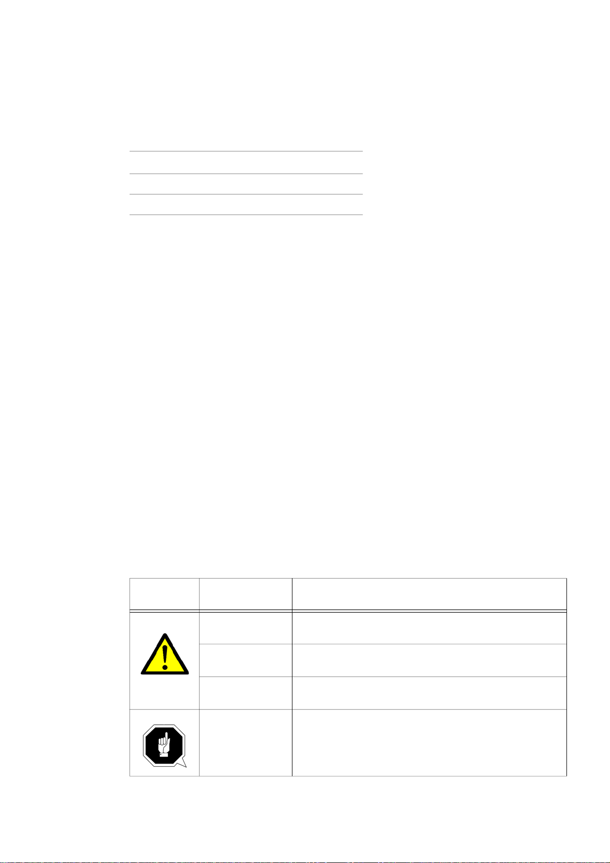
1.1.1 Classification of hazards
We classify the safety warnings into various le vels. The table below gives an overview of the
classification of symbols (pictograms) and warnings for the specific danger and its (possible)
consequences.
Pictogram
Alarm expres-
sion
DANGER!
WARNING!
CAUTION!
ATTENTION!
Imminent danger that will cause serious injury or death to
personnel.
Risk: A danger that might cause serious injury or death to
personnel.
Danger or unsafe procedure that might cause injury to
personnel or damage to property.
Situation that could cause damage to the machine and
product and other types of damage.
No risk of injury to personnel.
Definition/Consequences
Page 4
Pictogram
Alarm expres-
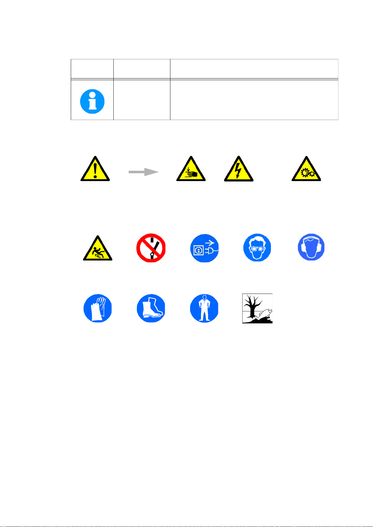
INFORMATION
In the case of specific dangers, we replace the pictogram by
general danger with a warning
1.1.2 Other pictograms
sion
of
Definition/Consequences
Application tips and other important or useful information
and notes.
No dangerous or harmful consequences for personnel or
objects.
or
injuries to
hands,
hazardous elec-
trical voltage,
rotating parts.
Caution
slide risk!
Use protective
gloves!
Activation forbid-
den!
Use protective
boots!
Pull the mains
plug!
Wear a safety suit! Protect the envi-
Use protective
goggles!
ronment!
Use ear protec-
tion!
Page 5
1.2 Proper user
Usage
WARNING!
Improper use of the circular metal saw
• will endanger personnel,
• will endanger the machine and other material property of the operator,
• may affect proper operation of the machine.
The circular metal saw is designed and manufactured to be used in environments where there is
no potential danger of explosion.
The circular metal saw is designed and manufactured to saw cold metals, cast materials and
other plastic materials that are not harmful to health and do not generate dust.
The circular metal saw must not be used on wood.
The pieces to be cut need to be of a shape that will allow them to be securely attached in the
work holder vice and ensure that the piece does not come loose when it is being sawed.
Improper
use
The circular metal saw must only be installed and operated in a dry and well-ventilated place.
If the circular metal saw is used in any way other than as described above, modified without the
authorisation of Optimum Maschinen GmbH or operated with different process data, then it is
being used improperly.
We do not take liability for damage caused by improper use.
We would like to stress that any modifications to the construction, or technical or technological
modifications that have not been authorised by Optimum Maschinen GmbH will also render the
guarantee null and void.
It is also part of proper use that
• the maximum values of the circular metal saw are complied with,
• the operating manual is observed,
• inspection and maintenance instructions are observed.
“Technical data“ on page 14
In order to achieve the required cutting performance and the angular tolerance the correct
choice of the saw blade, the cutting speed and the coolant are decisive.
WARNING!
Very serious injury.
It is forbidden to make any modifications or alterations to the operating values of the circular metal saw! These could en danger personnel and cause damage to the machine.
1.3 Possible dangers caused by the circular metal saw
The circular metal saw is state-of-the-art, but there is a residual risk, as the circular metal saw is
working with
• electrical voltage and currents
• a running circular metal saw blade.
We have used construction resources an d safety techniques to minim ise the health risk to per-
sonnel resulting from these hazards.
If the circular metal saw is used and maintained by staff who are not duly qualified, there may be
a risk resulting from incorrect operation or unsuitable maintenance.
Page 6
INFORMATION
All staff involved in assembly, commissioning, operation and maintenance must
• be duly qualified,
• follow this operating manual.
In the event of improper use
• there may be a risk to the staff,
• there may be a risk to the circular metal saw and other material property,
• the proper operation of the circular metal saw may be affected.
Disconnect the circular metal saw whenever cleaning or maintenance work is being carried out.
WARNING!
THE CIRCULAR METAL SAW MAY ONLY BE USED WITH THE SAFETY DEVICES ACTIVATED.
Disconnect the circular metal saw whenever you detect a failure in the safety devices or
when they are not fitted!
All additional installations carried out by the operator must incorporate the pre s crib e d
safety devices.
Being the machine operator, this will be your responsibility!
“Safety devices“ on page 8
1.4 Qualification of personnel
1.4.1 Target group
This manual is addressed to
•users,
• operators,
• maintenance staff.
The warning notes therefore refer to both operation and maintenan ce of the circular metal saw.
Determine clearly and irrevocably who will responsible for the different activities on the machine
(use, maintenance and repair).
Vague or unclear assignment of responsibilities constitute a safety hazard!
Always disconnect the circular metal saw from the power supply and secure the circular metal
saw against restarting.
1.4.2 Authorised personnel
WARNING!
Incorrect use and maintenance of the circular metal saw constitutes a danger for the
staff, objects and the environment.
Only authorised personnel may operate the circular metal saw!
The only staff authorised to use this machine and perform maintenance on it are trained and
instructed technical staff working for the operator and manufacturer.
Obligations
of the opera-
tor
The operator must
•train staff,
Page 7

• instruct staff regularly (at least once a year) on
- all safety standards that apply to the machine,
- operation,
- accredited technical guidelines,
• check staff‘s understand,
• document training/instruction,
• require staff to confirm participation in training/instruction by a signature,
• check whether the staff are aware of safety an d of dangers in the workplace and whether
they observe the operating manual.
The user must
Obligations
of the user
Additional
qualification
require-
ments
• have received training in operatio n of th e circular metal saw,
• know the function and principle of operation,
• before the machine is first used
- have read and understood the operating manual,
- be familiar with all safety devices and regulations.
For work on the following machine components there are additional requirements:
• Electrical components or devices: This work must only be carried out by a qualified electrician or person working under the instructions and supervision of a qualified electrician.
Before carrying out work on electric components or operating units the following measures
must be taken, in the order given.
- Disconnect all poles
- Ensure that the machine cannot be turned on again
- Check that there is no voltage
1.5 User positions
The user must stand in front of the circular metal saw.
INFORMATION
The mains plug of the circular metal saw must be freely accessible.
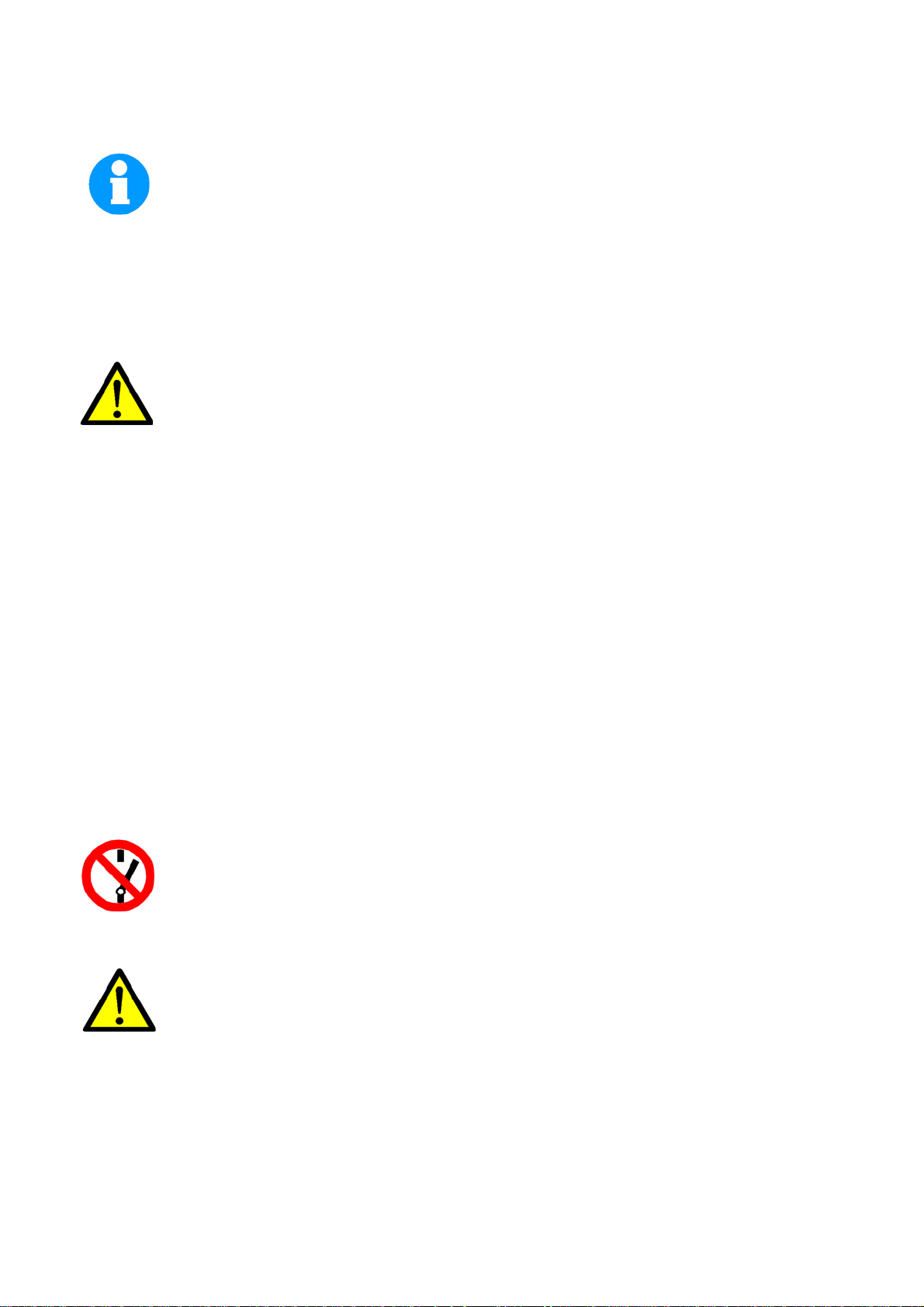
1.6 Safety devices
Use the circular metal saw only with properly functioning safety devices.
Stop the circular metal saw immediately if there is a failure in the safety device or if it is not func-
tioning for any reason.
It is your responsibility!
If a safety device has been activated or has failed, the circular metal saw must only be used
when
• the cause of the failure has been removed,
• it has been verified that there is no resulting danger for the staff or objects.
WARNING!
If you bypass, remove or override a safety device in any other way, you are endangering
yourself and other staff working with the circu lar metal saw. The possible consequences
are:
• damage as a result of components or parts of components flying off at high speed,
• contact with rotating parts,
Page 8
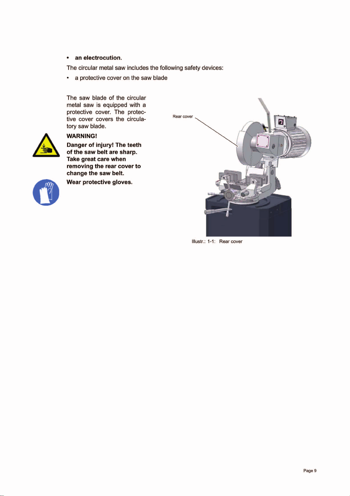
1.6.1 Prohibition, warning and mandatory labels
INFORMATION
All
warning labels must be legible.
eck them regularly.
Ch
Positions of labels on the circular metal saw:
Illustr.: 1-2: circular metal saw CS350
Check the circular metal saw at least once per shift. Inform the person responsible immediately
of any damage, defect or change in operating function.
ck all safety devices
Che
• at the beginning of each shift (with the machine stopped),
• once a week (with the machine in operation),
• after every maintenance and repair operation.
Che
ck if the prohibition, warning and information labels and the markings on the circular metal
w
sa
• can be identified (if not, clean them),
• are complete.
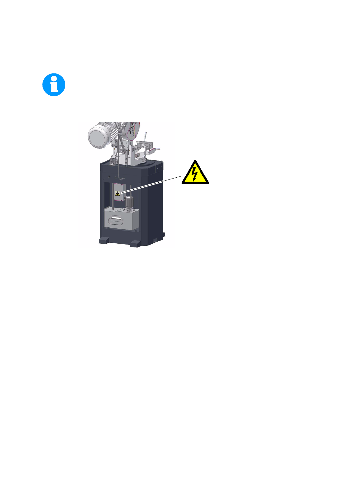
1.7 Individual protection gear
For certain work individual protection gear is required. This includes:
• safety helmet,
• protective goggles or face guard,
• protective gloves,
• safety shoes with steel caps,
• ear protection.
ore starting work, make sure that the prescribed individual protection gear is available at the
Bef
rkplace.
wo
Page 10
CAUTION!
Dirty or contaminated personal protection gear can cause disease. Clean your personal
protection gear after each use, regularly, at least once a week.
Personal protection gear for special work
Protect your face and eyes: During all work, and specifically work during which your face and
eyes are exposed to hazards, a safety helmet with a face guard should be worn.
Use protective gloves when lifting or handling pieces with sharp edges.
Wear safety shoes when fitting, dismantling or transporting heavy components.
1.8 Safety during operation
In the description of work with and on the circular metal saw we highlight the dangers specific to
that work.
WARNING!
Prior to activating the circular metal saw please double-check that this will
• not endanger anybody,
• not cause any damage to property.
Avoid unsafe working practises:
• Make sure your work does not endanger anyone.
• The instructions in this manual need to be observed during assembly, handling, maintenance and repair.
• Do not work on the circular metal saw if your concentration is reduced, for exampl e, because
you are taking medication.
• Observe the rules for preventing accide n ts issued by your association for the prevention of
occupational accidents and safety in the workplace or other inspection authorities.
• Stay at the circular metal saw until all rotating parts have come to a halt.
• Use prescribed protection gear. Make sure to wear a well-fitting work suit and, where necessary, a hairnet.
• Inform the inspector of any danger or failure.
Page 11
1.9 Safety during maintenance
Report and
document
any changes
Inform operating staff in good time of any repair and maintenance work.
Report all safety-relevant changes or performance details of the circular metal saw. Document
all changes, have the operating manual changed accordingly and train the machine operators.
1.9.1 Disconnecting the circular metal saw and making it safe
Unplug the circular metal saw from the mains before beginning any maintenance or r epair work.
Place a warning sign on the machine.
1.9.2 Using lifting equipment
WARNING!
Use of unstable lifting equipment and load-suspension devices that break under load ca n
cause very serious injuries or even death.
Check that the lifting and load suspension gear
• is of sufficient load capacity,
• in perfect condition.
Observe the preventing of accidents issued by your association for the prevention of
occupational accidents and safety in the workplace or other inspection authorities.
Hold the loads properly.
Never walk under suspended loads!
1.9.3 Mechanical maintenance work
Remove all protection and safety devices before beginning maintenance work and re-install
them once the work has been completed. They include:
• covers,
• safety indications and warning signs,
• earth (ground) connection.
If you remove protection or safety devices, refit them immediately after completing the work.
Check that they are working properly!
1.10 Accident report
Inform your superiors and Optimum Maschinen Germany GmbH immediately in the event of
accidents, possible sources of danger and any actions which almost led to an accident (near
misses).
These near misses can have many causes.
The sooner they are notified, the faster the causes can be eliminated.
INFORMATION
In the description of the execution of work with and on the circular metal saw, we highlight the
dangers specific to that work.
Page 12

1.11 Electrical system
Have the machine and/or the electric equipment checked regularly, and at least every six
months.
Eliminate immediately all defects such as loose connections, defective wires, etc.
A second person must be present during work on live components, to disconnect the power in
the event of an emergency.
Disconnect the circular metal saw immediately if there are any anomalies in the power supply!
“Maintenance“ on page 28, “Wiring diagram“ on page 39
Page 13
CS350
400
1.1
400
110x110 mm
95x95
110
135
110
110 110
110
/1.1KW
110
110 90
95 95

2.5 Dimensions
Height of work area [mm] 1540
dth [mm] 640
Wi
Weight circular metal saw [kg] 255
Saw blade diameter [mm] 350
“Dimensions of sawing flange“ on page 33
ge vice 145
Ran
2.6 Speed of saw blade
Two-step drive engine [m/min] 19 38
2.7 Environmental conditions
Temperature 5-35 °C
Humidity 5 - 80 %
2.8 Operating material
Spindle of the machine vice Commercial heavy grease
2.9 Emissions
The level of noise (emission) emitted by the circular metal saw is less than 80 dB(A).
the circular metal saw is installed in an area where various machines are in operation, the
If
acoustic influence (emission) on the operator of the circular metal saw may exceed the legally
permitted peak value of 85 dB(A) in the workplace.
INFORMATIO
We recommend the use of soundproofing and ear protection.
The duration of the noise pollution, the type of characteristics of the working area, such as other
machines which are operated simultaneously, influence the development of noise at the workplace.
Helical gear Mobilgear 629, viscosity 40°C 150 mm2/
at 100°C 16 mm2/s
s ,
IS
O VG 150
Plain bearing Commercial heavy grease
Bla
nk steel parts e.g. machine oil (Mobil oil, Fina, ...),
motor
oil, motor oil is acid-, stain- and
resin-free.
N
Page 15

3 Assembly
INFORMATION
The circular metal saw comes pre-assembled.
3.1 Extent of supply
When the machine is delivered, immed iately check that the circular metal saw has not been
damaged during shipping and that all components are included. Also check that no fastening
screws have come loose.
INFORMATION
In the default delivery volume, no saw blade is included. If required, you can order saw blades of
three different toothings.
3.2 Storage
“Spare part list“ on page 37
ATTENTION!
Improper storage may cause important parts to be damaged or destroyed.
Store packed or unpacked parts only under the intended environmental conditions.
“Environmental conditions“ on page 15
Consult Optimum Maschinen Germany GmbH if the circular metal saw and accessories have to
be stored for a period of more than three months or under different environmental conditions to
those given here.
3.3 Installation and assembly
3.3.1 Requirements of the installation site
Organise the work area around the circular metal saw in accordance with local safety regulations.
“Dimensions“ on page 14
Operation, maintenance and repair in the work area must not be hindered.
INFORMATION
The mains plug of the circular metal saw must be freely accessible.
Page 16

3.3.2 Fasten the substructure of the circular metal saw on the floor
Fasten the substructure on the floor with shear connector screws M12.
Illustration: 3-1: Machine substructure
Machine substructure
Fastening holes
Page 17

3.3.3 Mount the saw on the machine substructure
ATTENTION!
Danger of crushing
and overturning.
Proceed with caution
during the work
described below.
CAUTION!
The circular metal saw
needs to be mounted
on the machine substructure by at least
two persons.
Put the circular metal saw on the machine substructure.
Fasten the circular metal saw with the hexagon socket screws on the machine substructure.
3.3.4 Mount the lever arm
Mount the lever arm on the saw
head.
Machine substruc-
ture
Hexagon socket
screw
Illustr.: 3-2: Mount the saw on the machine substructure.
Hand-actuated
auxiliary switch
3.3.5 Mount the saw blade
Mount your saw blade “Mounting and replacing the saw blade“ on page 32
Page 18
Lifting arm
Strain relief
Connecting cable
Connecting cable
Hand-actuated
auxiliary switch
Illustr.: 3-3: Mount lever arm

3.4 First use
WARNING!
Personnel and equipment may be endangered if the circular metal saw is first used by
inexpert staff.
We do not take liability for any damage caused by incorrect commissioning.
3.4.1 Checking
Check the following.
ATTENTION!
Danger of cutting! Proceed with caution during the work described below. Use the pre-
scribed protection equipment.
3.4.2 Direction of the saw teeth
Check the direction of
the saw teeth. The saw
teeth need to be oriented in the direction of
the illustrated arrow.
Running direction
Saw blade
3.4.3 Check the oil level in the worm gear
Illustration: 3-4: Running direction of saw blade
Check the oil level in the worm gear of the circular metal saw.
“Check oil level, change gear oil.“ on page 30
Fill in gear oil, if required.
Page 19

3.4.4 Fill in coolant
CAUTION!
Da
nger of destroying the pump by dry running.
en the circular metal saw is switched on, the coolant pump is switched on.
Wh
The pump is lubricated by coolant.
Do not operate the pump without coolant.
“Filling in / Rinsing / Replacing“ on page 31
3.4.5 Power supply
Connect the mains plug of the circular metal saw with your power supply. Control the fusing
(fuse) of the power supply according to the technical indications for the power input of the circular metal saw.
INFORMATIO
For the connection, a CEE-415V-16 A connection cable needs to be connected.
CA
UTION!
ase pay attention that all 3 phases (L1, L2, L3) are connected correctly.
Ple
Most engine failure result from incorrect connection, for instance the neutral conductor
(N) is being connected to a phase.
This might lead to following results:
• The engine does get quickly very hot.
• The engine noise increases.
• The engine has no power.
N
3.4.6 Check the running direction of the saw blade
CAUTION!
the rotary field!
Mind
The saw blade is running clockwise.
eck the turning direction of the circular metal saw. The circular metal saw has to turn
Ch
direction as described in
in
page 19.
If the turning direction is wrong, please exchange two of the three phases on your cable
connection or on your power supply.
Make sure that the turning direction of any other power supply is not wrong. “Qualifikation des Personals“ on page 8
Illustration: 3-4: “Running direction of saw blade“ on
Page 20

CS350

4.3 Insert workpiece
The machine vice serves
as clamping device of
the workpiece.
The machine vice consists of
• the working table,
• the clamping jaws,
• the hand wheel.
The clamping jaws at the
front and back are
moved simultaneously,
this way the machine
vice will clamp the clamp
parts centrically.
Insert the workpiece
which needs to be
sawed into the
machine vice.
ATTENTION!
Danger of overturning of the
circular metal saw if the
machine substructure had
not been fixed to the floor.
Support long workpieces
before pushing the piece to
be cut into the machine vice.
Clamping jaws
Workpiece
Hand wheel
Illustration: 4-2: Machine vice
Workpiece
Material stand
Page 22
Turn the hand wheel to the
right until the workpiece is
firmly clamped.
CAUTION!
Make sure if the workpiece is
really firmly clamped.
Illustration: 4-3: Machine vice
Workpiece
Hand wheel
Illustration: 4-4: Hand wheel


Toothing
Massive material
Profile material
Illustration: 4-6: Table for toothing
Example:
Profile material wall thickness 3 mm = toothing 10
Massive material diameter 40 mm = toothing 12
Page 24

4.5 Switching on the machine
Connect the mains plug with the power supply.
Select speed level 1 or 2.
Actuate the hand-actuated
switch at the handle of the
lever arm.
Pull the lever arm down-
ward towards the workpiece.
Hand-actuated aux-
iliary switch
Lever arm
Step switch
4.6 Switching off the machine
Push the lever arm upward.
Release the hand-actuated
auxiliary switch at the handle of the lever arm.
Switch the step switch to the
position 0.
Illustration: 4-7: Hand-actuated auxiliary switch an step switch
Hand-actuated auxil-
iary switch
Lever arm
Step switch
Illustration: 4-8: Hand-actuated auxiliary switch and step
switch
Page 25

4.7 Sawing of angles
The circular metal saw can be turned from -45° to 45° in order to allow angular saw cuts.
Angle scale
Locking lever cutting angle
Illustration: 4-9: Setting of angle cut
CAUTION!
Make sure that the saw is clean and free of chips in the slewing area before adjusting it.
Loosen the locking lever.
Turn the saw to the required cu tting position with the help of the angle scale.
Retighten the locking lever.
Move the locking lever to
the right in order to
release the bearing
block.
Locking lever
Adjust the saw to the
required position with the
help of the angle scale.
Move the locking lever to
the left in order to reclamp the bearing block.
Page 26
Illustration: 4-10: Releasing clamping lever

4.8 Cooling
ATTENTION!
Damage to the pump in the event of dry running.
When the circular metal saw is switched on the coolant pump is switched on.
The pump is lubricated by the coolant. Do not start up the pump without coolant.
Turn the dosing stop valve in direction of the coolant hose until the coolant penetrates.
By the turning move high temperatures are generated at the lip of the tool by the occurring friction heat.
By cooling with an appropriate coolant/lubricant agent you will achieve better working results
and longer tool life of the saw blade.
Coolant pump
Coolant tank
Filling quantity about
8 litres
Illustration: 4-11: Coolant appliance
Dosing stop valve
(Flow blocked)
Coolant hose
INFORMATION
Use a water-soluble and non-pollutant emulsion as a cooling agent. This can be acquired from
authorised distributors.
Make sure that the cooling agent is properly retrieved.
Respect the environment when disposing of any lubricants and cooling agents.
Follow the manufacturer‘s disposal instructions.
Page 27

5 Maintenance
In this chapter you will find important information about
• inspection,
• maintenance,
•repair.
The diagram below shows which of these headings each task falls under.
MAINTENANCE
Inspection Maintenance
Measuring Rough cleaning Repairs
Testing Fine cleaning Replacing
Conserving
Lubricating
Completing
Replacing
Readjusting
Illustration: 5-1: Maintenance – definition according to DIN 31051
Repair
Adjusting
ATTENTION!
Properly-performed regular maintenance is an essential prerequisite for
• safe operation,
• fault-free operation,
• long service life of the machine and
• the quality of the products you manufacture.
Installations and equipment from other manufacturers must also be in optimum condition.
Page 28
ENVIRONMENTAL PROTECTION
Make sure that when working on the worm gear and on the coolant tank
• collection tanks are used where the collecting capacity is appropriate for the quantity
of liquids which needs to be collected.
• any spilt liquids and oils are not spilt on the ground.
Clean up any spilt liquid or oils immediately using proper oil-absorption methods and dispose of
them in accordance with current legal requirements on the environment.
Cleaning up spillages
Do not re-introduce liquids spilt outside the system during repair or as result of leakage from the
reserve tank: collect them in a special vessel to be disposed of.
Disposal
Never dump oil or other pollutant substances in water inlets, rivers or channels.

Used oils must be delivered to a collection centre. Consult your superior if you do not know
where the collection centre is.
5.1 Safety
WARNING!
The consequences of incorrect maintenance and repair work may include:
• Very serious injury to staff working on the machine,
• damage to the machine.
Only qualified staff should carry out maintenance and repair work on the machine.
5.1.1 Preparation
WARNING!
Only carry out work on the machine if it has been unplugged from the mains power sup-
ply.
Attach a warning label.
5.1.2 Restarting
Before restarting, run a safety check.
WARNING!
Prior to activating the machine please double-check that this will
• not endanger anybody,
• not damage the machine.
Page 29


INTERVAL WHERE? WHAT? HOW?
Regularly remove the chips which are accumulating below
the clamping jaws.
To do so, use a thin, flat brush.
as required
Vice
CAUTION!
as required
as required
every six
months
Arbor bearing block
Machine vice
Cleaning the vice
• Lubricate the arbor of the beari ng block
Lubricate
Illustration: 5-3: Bearing block
• Lubricate the spindle of the machine vice at the provided lubricat-
•
Spindle
Never clean the vice with compressed air.
ing nipples.
Type of lubricating oil, “Operating material“ on page 15
The coolant pump is almost maintenance-free.
• Replace the cooling agent regu larly, depending on usage.
• Rinse the coolant pump when using coolants which leave residues.
• In order to exchange the coolant liquid, pump it into an appropriate collecting vessel and refill the coolant liquid.
Lubricating nipple
Arbor
Bearing block
Coolant system
INFORMATION
The filling quantity amounts to about 8 litres. Thus
Filling in / Rinsing / Replacing
according to
wear
Saw blade
Replacing the saw blade
the tank is filled about 2/3 of its filling capacity.
“Mounting and replacing the saw blade“ on page 32
INFORMATION!
The spindle bearing is prelubricated. No lubricating is required.
Page 31


5.3.1 Dimensions of sawing flange
Sawing flange
5.4 Repair
For any repair work, get assistance from an employee of Optimum Maschinen GmbH‘s technical
service or send us the circular metal saw.
If the repairs are carried out by qualified technical staff, they must follow the indications given in
this manual.
Optimum Maschinen Germany GmbH does not take any responsibility nor does it guarantee
against damage and operating anomalies resulting from failure to observe this operating manual.
For repairs, only use
Sawing spindle
Illustration: 5-6: Sawing flange
• faultless and suitable tools
• original spare parts or parts from series expressly authorised by Optimum Maschinen Germany GmbH.
Page 33

6 Ersatzteile - Spare parts - CS350
6.1 Ersatzteilzeichnung - Explosion drawing
34
Abb.6-1: Übersicht Metallkreissäge - Overview saw
18.10.06

6.1.1 Einzelteile - Spare parts - CS350
106
98
103
104
10
2
10
0
99
123
12
4
12
5
98
97
96
95
94
10
7
93
92
110
8
10
10
10
113
11
9
1
91
114
1
112
116
115
117
119
118
122
121
12
0
79
80
Abb.6-2: Vorderansicht - Front view
87
86
85
84
83
82
81
80
79
77
78
75
76
73
74
72
88
90
89
60
62
70
66
71
57
58
59
61
63
64
65
67
68
69
53
56
55
54
52
51
50
18.10.06
Abb.6-3: Hinteransicht - Opinion behind
35

42
43
41
39
38
37
44
45
46
47
49
35
48
36
34
33
32
31
30
29
36
21
27
20
22 23
28
Abb.6-4: Schnellspannschraubstock - Machine vice
17
18
19
24
25
26
Abb.6-5: Maschinenunterbau - Machine substructure
16
14
13
1
2
3
5
7
8
4
10
40
11
6
9
12
15
18.10.06

6.2 Schaltplan - Wiring diagram - CS350
18.10.06
37

6.2.1 Ersatzteilliste - Spare parts list - CS350
38
.soP
Bezeichnung Designation
1 Zylinderschraube Socket-head cap screw 4 M5x10 033023001
2 Deckel Cover 1 033023002
3 Unterlegscheibe Washer 4 033023003
4 Kühlmittelschlauch Cooling agent hose 1 033023004
5 Kühlmittelschlauch Cooling agent hose 1 033023005
6 Pumpe Pump 1 033023006
7 Zylinderschraube Socket-head cap screw 4 M5x10 033023007
8 Unterlegscheibe Washer 4 033023008
9 Reduzierstück/ Schlauchklemme Reducer / Hose clip 1 033023009
10 Schaltkasten Switchbox 1 0330230010
11 Zylinderschraube Socket-head cap screw 4 M6x20 0330230011
12 Zylinderschraube Socket-head cap screw 4 M5x20 0330230012
13 PG-Verschraubung PG-screw connection 5 0330230013
14 Maschinenunterbau Machine stand 1 0330230014
15 Kühlmittelbehälter Coolant tank 1 0330230015
16 Reduzierstück Reducer 1 0330230016
17 Grundplatte Baseplate 1 0330230017
18 Ring Ring 1 0330230018
19 Gewindestück Threaded part 1 0330230019
20 Spannstange Linkage 1 0330230020
21 Griff Handle 1 0330230021
22 Unterlegscheibe Washer 2 0330230022
23 Spannmutter Tightening nut 1 0330230023
24 Mutter Nut 3 0330230024
25 Zylinderschraube Socket-head cap screw 3 M8x60 0330230025
26 Sechskantschraube Hexagon head screw 2 M12x30 0330230026
27 Schloß Lock 1 0330230027
28 Tür Door 1 0330230028
29 Mutter Nut 1 0330230029
30 Abdeckung Cover 1 0330230030
31 Nabe Hub 1 0330230031
32 Spannstange Linkage 4 0330230032
33 Griff Handle 4 0330230033
34 Passfeder Key 1 6x6 0330230034
35 Gewindewelle Threaded shaft 1 0330230035
36 Führungswelle Guide shaft 2 0330230036
37 Gewindestift Threaded pin 2 M8x10 0330230037
38 Unterteil Lower part 1 0330230038
39 Zylinderstift Cylindrical pin 2 10x30 0330230039
40 Motor Kühlmittelpumpe Motor cooling pump 1 03302300M2
41 Spannbacken Chuck jaws 2 0330230041
42 Zylinderschraube Socket-head cap screw 2 M10x25S 0330230042
43 Stützblock Supporting block 1 0330230043
44 Schutzblech Shield 1 0330230044
45 Mutter Nut 4 M10 0330230045
46 Spannbacken Chuck jaws 2 0330230046
47 Zylinderschraube Socket-head cap screw 4 M10x30 0330230047
48 Klemmbacke Clamping jaw 0330230048
49 Schmiernippel Lubrication fitting 2 0330230049
50 Arm Arm 1 0330230050
51 Sechskantschraube Hexagon head screw 2 M10x25 0330230051
52 Unterlegscheibe Washer 2 0330230052
53 Sägemotor Sawing motor 1 1,5 KW 03302300M1
54 PG-Verschraubung PG-screw connection 2 0330230054
55 Unterlegscheibe Washer 4 0330230055
56 Zylinderschraube Socket-head cap screw 4 M5x10 0330230056
57 Stufenschalter Step switch 1 03302300QS
58 Anschluss Connection 1 0330230058
59 Dichtung Seal 1 0330230059
60 Mutter Nut 1 0330230060
61 Zahnrad Gear wheel 1 Z=17; m=2 0330230061
62 Zylinderschraube Socket-head cap screw 8 M10x20 0330230062
63 Schmiernippel Lubrication fitting 2 0330230063
64 Montagewinkel Assembly angle 1 0330230064
65 Sechskantschraube Hexagon head screw 4 M10x25 0330230065
66 Unterlegscheibe Washer 4 0330230066
67 Feder Spring 2 0330230067
e Grösse Artikelnummer
Meng
Qty. Size Item no.
18.10.06

Pos.
Bezeichnung Designation
68 Sechskantschraube Hexagon head screw 2 M10x25 0330230068
69 Arm Arm 1 0330230069
70 Unterlegscheibe Washer 2 0330230070
71 Mutter Nut 1 0330230071
72 Zahnrad Gear wheel 1 Z=31; m=2 0330230072
73 Abstan dsring Space ring 1 0330230073
74 Zylinderschraube Socket-head cap screw 4 M10x20 0330230074
75 Sicherungsring Snap ring 1 0330230075
76 Lager Bearing 1 6206 0330230076
77 Ring Ring 1 0330230077
78 Axiallager Axial-thrust bearing 1 81106TN 0330230078
79 Welle Shaft 1 0330230079
80 Skalenteilung Scale 1 0330230080
81 Paßfeder Key 1 10x8x25 0330230081
82 Schneckenwelle Worm shaft 1 0330230082
83 Nadellager Needle bearing 1 BK3026 0330230083
84 Sägekopfgehäuse Sawing head housing 1 0330230084
85 Sichtglas Sight glass 1 0330230085
86 Zylinderschraube Socket-head cap screw 4 M5x10 0330230086
87 Typenschild Identification plate 1 0330230087
88 Stopfen Plug 2 0330230088
89 Rändelmutter Knurled nut 1 0330230089
90 Zylinderschraube Socket-head cap screw 1 M10x60 0330230090
91 Dichtung Seal 1 45x65x14 0330230091
92 Sägespindel Sawing spindle 1 0330230092
93 Sägeblatt Saw blade 1 HSS 4 ZpZ 3357454
93 Sägeblatt Saw blade 1 HSS 6 ZpZ 3357456
93 Sägeblatt Saw blade 1 HSS 8 ZpZ 3357458
94 Zylinderstift Cylindrical pin 1 8x20 0330230094
95 Sägeflansch Sawing flange 1 0330230095
96 Zylinderschraube Socket-head cap screw 1 M10x25 0330230096
97 Gelenkhaube Joint hood 1 0330230097
98 Bolzen Bolt 4 0330230098
99 Kupplungsstange Coupling rod 1 0330230099
100 Zentrierhülse Centering case 1 03302300100
101 Zylinderschraube Socket-head cap screw 3 M10x60 03302300101
102 Absperrhahn Shut-of f valve 1 03302300102
103 Ring Ring 1 03302300103
104 Kupplungsstange Coupling rod 1 03302300104
105 Stehbolzen Bolt 1 03302300105
106 Kupplungsstange Coupling rod 1 03302300106
107 Abstandscheibe Shim 1 03302300107
108 Kupplungsstange Coupling rod 1 03302300108
109 Sicherungsring Snap ring 5 10x0,5 03302300109
110 Schutzhaube Protection hood 1 03302300110
111 Lagergehäuse Bearing cover 1 03302300111
112 Sicherungsring Snap ring 1 78x2,5 03302300112
113 Lager Bearing 1 6207 03302300113
114 O-Ring O ring 1 75x2,7 03302300114
115 Buchse Socket 1 03302300115
116 Schneckenrad Worm gear 1 03302300116
117 Sicherungsring Snap ring 1 32x1,5 03302300117
118 Nadellager Needle bearing 1 BK3026 03302300118
119 Kabel Cable 1 03302300119
120 Hebelarm Lever arm 1 03302300120
121 Griff Handle 1 03302300121
122 Drucktaster Ein Push button on 1 03302300SB
123 Sicherungsring Snap ring 1 32x1,5 03302300123
124 Buchse Socket 1 03302300124
125 Scheibe Shim 1 03302300125
126 O-Ring O-ring 1 40x3 03302300126
M1 Sägemotor Sawing motor 1 1,5 KW 03302300M1
M2 Motor Kühlmittelpumpe Motor cooling pump 1 0,4 KW 03302300M2
QS Stufenschalter Step switch 1 03302300QS
KM Motorschütz Motor contactor 1 03302300KM
TC Transformator Transformer 1 03302300TC
SB Drucktaster Ein Push button on 1 03302300SB
Menge Grösse Artikelnummer
Qty. Size Item no.
18.10.06
39

7 Anomalies
7.1 Anomalies in the circular metal saw
ANORMALTY
Saw motor overloaded
Engine is not running
Short life of saw belt
(Teeth blunt)
Breaking of teeth
CAUSE/
POSSIBLE EFFECTS
• Suction of motor cooling air hindered
• Motor not correctly fixed
• Power unit for saw belt not correctly fixed
• Engine connected incorrectly
• Relay or engine defective
• Step switch is switched to position
0/ OFF
• Thermal protection of the engine is
defective
• Quality of saw belt not suitable for
this material
• An incorrect toothing causes
breakage of teeth (the broken
tooth in the workpiece blunts the
other teeth)
• Missing cooling
• Cutting speed too high
• Chip space in the saw belt full,
toothing incorrect
SOLUTION
• Check and clean
• Requires technical service! Have
the machine repaired in the workshop
• Request help of electric al specialists
• Saw belt with higher quality
• Select correct toothing
• Use coolant system
• Reduce cutting speed
• Use saw belt with different toothing or reduce feed
Twisted cut (saw belt deviating)
Saw excessively jerks or
breaks
Cut not rectangular, but
parallel
Cooling does not work
• Saw belt blunt
• Cutting pressure too high
• Saw belt defective (irregular set)
• Cutting speeds too high
• Teeth too blunt or too small gaps
between the teeth
• Saw jerks as chips remain in the
gaps of the saw blade
• The saw is installed reverse to the
turning direction
• Material not resting on both vice
rails
• Vice jaws not adjusted to 90°
• The valve on the sawing hood is
closed
• The pump is not connected
• Pump defective
• Coolant tank empty
• Suction tube of the coolant pump
is blocked
• Wrong turning direction of the
pump
•Replace
• Reduce
•Replace
• Have saw grinded and the gaps
between the teeth polished
• Turn round the saw and check the
teeth
• Support material properly
• Correctly adjust the circular metal
saw
Page 40

8 Appendix
8.1 Copyright
© 2006
This document is copyright. All derived rights are also reserved, especially those of translation,
re-impression, use of figures, broadcast, reproduction by photo-mechanical or similar means
and recording in data processing systems, whether partial or to tal.
The company reserves the right to make technical alterations without prior notice.
8.2 Terminology/ Glossary
TERM EXPLANATION
Work piece
Material stop
Protective cover of
saw blade
Clamping jaws
Quick-action vice
Drive motor
High-strength cable
gland
• Piece to be milled, drilled or machined.
• Position for several sawings
• Sawing stop
• Casing on the saw blade
• Clamping rail of the machine vice
• Clamping device for the workpiece
• Sawing motor
• Strain relief of the electrical connection
Page 41

8.3 Warranty
Within the term of warranty, the company Optimum warrants for a perfect quality of its products
and will reimburse any cost for overhaul or exchange of defective parts in case of construction
error, fault in material and/or defect of fabrication.
The term of warranty for commercial use is 12 months and for use as an amateur it is 24
months. Condition for a warranty claim due to construction errors, faults in material and/or
defects of fabrication is:
• Proof of purchase and that the instructions for use had been followed.
In order to assert the claim of warranty, you have to present a typescript original receipt of
purchase. It must comprise the complete address, date of purchase and type designation o f
the product.
The instruction for use the corresponding device as well as the safety information need to be
observed. Damages due to operator‘s mistakes may not be accepted as warranty claims.
• Correct use of the devices.
The products of the company Optimum had been designed and built for certain purposes.
They are listed in the operating manual.
The warranty claim may not be accepted if the operating manual is not being followed properly or it is used for a purpose which has not been intended or with improper accessory.
• Maintenance work and cleaning.
It is absolutely necessary to maintain and clean the machine in regular intervals according to
prescriptions of the instruction for use.
By intervention of a third party, and warranty claim will expire. Maintenance work and cleaning are usually not part of the claim of warranty.
• Original spare parts
Make sure to use only original spare parts and original accessory. This can be acquired from
authorized distributors of the machine.
When other than original parts are being used, consequential damages may occur and danger of accidents will increase. Disassembled or partially disassembled devices and devices
which are repaired with foreign parts are excluded from warranty claims.
• Wearing parts
Certain components are subject to wear out by time respectively a standard wear by use on
the corresponding machine.
Among these components are e.g. V-belts, ball bearings, switches, mains cables, gaskets
and washers, etc. These wearing parts are not part of the warranty.
8.4 Disposal
Disposal of used electric and electronic machines
(Applicable in the countries of the European Union and other European countries with a sepa-
rate collecting system for those devices).
The sign on the product or on its packing indicates that the product must not be handled as
common household waist, but that is needs to be delivered to a central collection point of recycling. Your contribution to the correct disposal of this product will protect the environment and
the health of your fellow men. The environment and the health are endangered by incorrect disposal. Recycling of material will help to reduce the consumption of raw materials. Your District
Office, the municipal waste collection station or the shop where you have bought the product will
inform you about recycling of this product.
8.5 RoHS , 2002/95/CE
The sign on the product or on its packing indicates that this product complies with the European
guideline 2002/95/EC .
Page 42

8.6 Product follow-up
We are required to perform a follow-up service for our products which extends beyond shipment.
We would be grateful if you could send us the following information:
• modified settings,
• experiences with the circular metal saw, which could be important to other users,
• repeated failures
Page 43

8.7 EC-Declaration of Conformity
hereby declares that the following product,
Machine type: Circular metal saw
Name of the machine: CS350
levant EU directives:
Re
Machine Directive 98/37/EG, Annex II A
EMV
Directive 89/336/EWG
Low Voltage Directive 73/23/EWG
meets the provisions of the aforementioned directive, including any amendments valid at the
time of this statement.
In
order to ensure conformity, the following harmonized standards in particular have been
applied:
EN
60034-1: 09/2000 Rotating electrical machines - Part 1: Rotating and operating char-
acteristics.
EN
60034-9: 06/1998 Rotating electrical machines - Part 9: Noise limits.
60204-1:11/1998 Safety of machinery - Electrical equipment of machines - Part 1:
EN
General requirements
EN 62079:2001
DIN
Editing
of instruction - structure, content and illustration
(VDE 0039)
62079:2001
IEC
Page 44
 Loading...