

Corken HG601 Series, THG601 Series, HG602 Series, THG602 Series Installation, Operation & Maintenance Manual
ORIGINAL INSTRUCTIONS IJ100D
Installation, Operation
& Maintenance Manual
Plain & T-Style Double-Acting Gas Compressors
Models HG601, HG602, THG601 & THG602 Series
Model THG602BE
(T-style )
Model HG601EE
(Plain style)
Warning: (1) Periodic inspection and maintenance of Corken products is essential. (2) Inspection, maintenance and installation of Corken products must be made
only by experienced, trained and qualified personnel. (3) Maintenance, use and installation of Corken products must comply with Corken instructions, applicable laws
and safety standards (such as NFPA Pamphlet 58 for LP-Gas and ANSI K61.1-1972 for Anhydrous Ammonia). (4) Transfer of toxic, dangerous, flammable or explosive
substances using Corken products is at user’s risk and equipment should be operated only by qualified personnel according to applicable laws and safety standards.

Warning
Install, use and maintain this equipment according to Corken, Inc. instructions and all applicable federal, state, local
laws and codes, and NFPA Pamphlet 58 for LP-Gas or ANSI K61.1-1989 for Anhydrous Ammonia. Periodic inspection
and maintenance is essential.
Corken One Year Limited Warranty
Corken, Inc. warrants that its products will be free from defects in material and workmanship for a period of one
year from date of installation, provided that the warranty shall not extend beyond twenty-four (24) months from the
date of shipment from Corken. Corken products which fail within the warranty period due to defects in material or
workmanship will be repaired or replaced at Corken’s option, when returned freight prepaid to: Corken, Inc., 3805
N.W. 36th Street, Oklahoma City, Oklahoma 73112.
Parts subject to wear or abuse, such as mechanical seals, blades, piston rings, valves, and packing, and other
parts showing signs of abuse are not covered by this limited warranty. Also, equipment, parts and accessories not
manufactured by Corken but furnished with Corken products are not covered by this limited warranty and purchaser
must look to the original manufacturer’s warranty, if any. This limited warranty is void if the Corken product has been
altered or repaired without the consent of Corken.
ALL IMPLIED WARRANTIES, INCLUDING ANY IMPLIED WARRANTY OF MERCHANTABILITY OR FITNESS
FOR A PARTICULAR PURPOSE, ARE EXPRESSLY NEGATED TO THE EXTENT PERMITTED BY LAW AND
SHALL IN NO EVENT EXTEND BEYOND THE EXPRESSED WARRANTY PERIOD.
Corken disclaims any liability for consequential damages due to breach of any written or implied warranty on Corken
products. Transfer of toxic, dangerous, flammable or explosive substances using Corken products is at the user’s
risk. Such substances should be handled by experienced, trained personnel in compliance with governmental
and industrial safety standards.
Contacting The Factory
For your convenience, the model number and serial number are given on the compressor nameplate. Space is
provided below for you to keep a written record of this information.
Always include the model number and serial number when ordering parts.
Model No.
Serial No.
Date Purchased
Date Installed
Purchased From
Installed By
2

Table of Contents
FEATURES AND BENEFITS .....................................................................4
CHAPTER 1—INSTALLATION OF YOUR COMPRESSOR .............................................6
1.1 Location .................................................................................6
1.2 Foundation ...............................................................................6
1.3 Piping ...................................................................................6
1.4 Liquid Trap ...............................................................................7
1.5 Driver Installation and Flywheels ..............................................................8
1.6 Crankcase Lubrication ......................................................................9
1.7 Crankcase Oil Pressure Adjustment ...........................................................9
1.8 Relief Valves .............................................................................10
1.9 Shutdown/Alarm Devices ...................................................................10
CHAPTER 2—STARTING UP YOUR CORKEN COMPRESSOR .......................................11
2.1 Inspection After Extended Storage ...........................................................11
2.2 Flywheel and V-belt Alignment ..............................................................11
2.3 Compressor Speed and Rotation Direction ....................................................12
2.4 Compressor Cooling ......................................................................12
2.5 Force Feed Cylinder Lubrication (Lubed models only) ............................................12
2.6 Variable Clearance Heads (VCH) .............................................................13
2.7 Startup Check List ........................................................................14
CHAPTER 3—ROUTINE MAINTENANCE CHART ..................................................15
CHAPTER 4—ROUTINE SERVICE AND REPAIR PROCEDURES ......................................15
4.1 Compressor Valves .......................................................................15
4.2 Heads ..................................................................................16
4.3 Piston Rings and Piston Ring Expander Replacement ............................................17
4.4 Pistons .................................................................................17
4.5 Cylinder Replacement .....................................................................18
4.6 Packing Replacement Instructions ...........................................................18
4.7 Bearing Replacement for Crankcase and Connecting Rod ........................................24
4.8 Oil Pump Inspection. . . . . . . . . . . . . . . . . . . . . . . . . . . . . . . . . . . . . . . . . . . . . . . . . . . . . . . . . . . . . . . . . . . . . . . 27
CHAPTER 5—EXTENDED STORAGE PROCEDURES ...............................................27
Compressor Troubleshooting ..................................................................28
Gasket Sets and Repair Kits ...................................................................29
Crankcase and Cylinder Kit Options .............................................................29
APPENDICES
A. Model Number Identification Code ............................................................30
B. Operating Specifications ....................................................................36
C. Outline Dimensions ........................................................................41
D. Assembly Details ..........................................................................45
3
Features and Benefits
Self-lubricating piston and rider rings:
Made of PTFE to ensure extended service life
Cylinder
nameplate
Adapter
Packing cartridge body:
Holds the outer and
middle sets of packing.
Packing cartridge adaptor:
Holds the inner oil wiper
ring set and inner packing
Lifting eye
Crankcase inspection plate
Crankcase
nameplate
Placement of valves:
Make inspection and maintenance simple.
(Optional) Thermostatically controlled crankcase heater:
Assures proper oil viscosity throughout all weather conditions.
Why Corken Compressors
are Special
1/4" Pipe plug
Distance piece:
Ensures greater leakage control
(Optional)
Oil divider valve assembly:
Ensures each cylinder has the
same amount of lubrication.
Oil lter
(Optional) Force-feed lubricator:
Assures proper lubrication of
cylinders and packing when required
Figure 1.1 (THG600 shown)
the crankcase. To further seal the compression chamber,
a crosshead/piston rod design with seals around the
piston rod is required.
Corken industrial gas compressors are unique among
compressors their size. Unlike ordinary lubricated gas
compressors, Corken compressors completely isolate
the pressurized gas in the compression chamber from
the crankcase. While piston rings seal the piston tightly
enough for it to do compression work, they do not provide
enough sealing to isolate the compression chamber from
By utilizing specialized piston-rod sealing systems,
Corken compressors can compress pressurized,
flammable and toxic gases. They can also be used to
compress harmless gases where oil-free compression
or elevated suction pressures are required. With a large
selection of design options available, Corken offers the
most versatile line of small gas compressors in the world.
4
Crankshaft journal, connecting rod
bearings, wrist pins, and crossheads:
Pressure lubricated by an oil pump with oil
ltered by a 10-micron spin on lter.
Heavy-duty cylinder design:
Each cylinder is hydrostatically tested to 1-1/2
times the rated working pressure for maximum
Flywheel
strength. A corrosion resistant coating (MC1002)
is available for all cylinder sizes. MC1002 extends
the life of the cylinder and piston rings.
Inner distance piece
(Barrier 1)
Outer distance piece
(Barrier 2)
Inner oil wiper ring set
Inner packing set
Oil deector ring
Middle packing set
Outer packing set
Variable clearance head:
Enables you to change
the capacity and
BHP requirements.
Heavy-duty crankcase:
A rugged, internally ribbed design,
incorporating heavy-duty main bearings
and four-bolt connecting rods
Corken Horizontal
Gas Compressors
Your new Corken horizontal compressor is a double-acting
reciprocating compressor; however, when an optional blank
valve is used, the compressor is single acting. Corken
horizontal compressors have a large number of configurations
to fit your individual requirements. They are manufactured as
single stage- or two-stage units. For more information on the
various configurations, refer to Appendix A.
5
Chapter 1—Installation Of Your Compressor
1.1 Location
NOTE: Corken compressors are designed to handle
toxic or flammable gases and should be located
outdoors in a well ventilated area.
Proper installation of your compressor is essential for
peak performance and reliable service. The installation
area should be clean, well ventilated and have ample
space to install and maintain your compressor. A
double-acting compressor generates more heat than
a typical single-acting compressor. As a result your
compressor should be located in an area where good
air flow and ventilation can be provided. In extreme
cases, external cooling fans can be used to provide
additional air flow across the cylinders. A minimum of
18 inches clearance between the unit and the nearest
wall is advisable. This space will allow access from all
sides and provide unrestricted air flow for adequate
cooling of the motor and compressor. The unit should
be firmly bolted to a solid, level base.
Corken compressors are designed and manufactured
for outdoor duty. For applications where the compressor
will be subjected to extreme conditions such as corrosive
environments or arctic conditions for extended periods
of time, consult Corken.
Check local safety regulations and building codes to
assure installation will meet local safety standards.
1.2 Foundation
Proper foundations are essential for a smooth running
compression system. The compressor should be
attached to a concrete slab a minimum of 8 inches
thick with a 2 inch skirt around the circumference of
the steel structural skid. The steel structural skid should
be securely anchored into the foundation by 3/4 inch
diameter “J” bolts that are 8 inches long. The total mass
of the concrete foundation should be approximately
twice the weight of the compressor system (i.e. steel
structural skid, compressor, motor, etc.). See figure 1.2
for details.
1.3 Piping
Proper piping design and installation is as important as a
proper foundation is to a smooth operating compressor.
Improper piping installation will result in undesirable
transmission of compressor vibration to the piping. The
compressor piping should be designed for the rate of
flow anticipated and for minimum pressure drop; in no
case should the piping be smaller than the compressor
nozzle to which it connects. If the length of the line must
exceed 100 ft., the next larger size pipe should be used.
Install a strainer at the compressor inlet. Never install
a shut-off valve in the discharge piping unless a safety
relief valve is placed in the line between the shut-off
valve and the compressor. Remember to consider future
expansion in your pipe sizing and layout.
Noise:
Corken horizontal compressors should not exceed an 85
DBA noise level when properly installed.
Note: The depth of the concrete foundation will
vary based on local soil conditions.
Main beam (C-Beam)
Concrete foundation
Hex nut
&
washer
Figur e 1.2
Cross beam (H-Beam)
3/4″ diameter “J” bolt
DO NOT SUPPORT PIPING WITH THE COMPRESSOR.
Unsupported piping is the most frequent cause of vibration
of the pipe. The best method to minimize transmission of
vibration from the compressor to the piping is to use
flexible connectors (see figure 1.3 for details).
Pipe must be adequately sized to prevent excessive
pressure drop between the suction source and the
compressor as well as between the compressor and the
final discharge point. In most cases, piping should be
at least the same diameter as the suction nozzle on the
compressor.
If a restrictive device such as a valve, pressure regulator,
or back-check valve is to be installed in the compressor’s
suction line, care must be taken. The suction line volume
between the restrictive device and the compressor
suction nozzle must be at least ten times the swept
cylinder volume.
On liquefied gas applications such as LPG, it is of
extreme importance to prevent the entry of liquid into
the compressor. Installing a liquid trap on the inlet side
will prevent liquid from entering the compressor (see
se ction 1.4).
6

Figure 1.3
Inlet flange
Discharge
flange
Flexible piping
connection
Flexible
piping
connection
Inlet manifold
Discharge manifold
Mounting base
Packing drain tank
It is of equal importance to protect the discharge side
of the compressor from liquid entry. This may be done
by installing a check valve on the discharge side of the
compressor and using a piping design that does not
allow liquid to gravity drain into the compressor.
For vapor recovery applications, be certain to install
a check valve on vapor lines discharging to the liquid
space of the tank.
All piping must be in accordance with the laws and codes
governing the service. In the United States, the following
codes apply:
For LP Gas—The National Fire Protection Association
Pamphlet No. 58, Standard for the Storage and Handling
of Liquefied Petroleum Gases.
For Ammonia—The American National Standards
Institute, Inc., K61.1-1989, Storage and Handling of
Anhydrous Ammonia.
Copies of these are available from NFPA, 60 Baterymarch
Street, Boston, Mass, 02110 and ANSI, 1430 Broadway, New
York, N.Y., 10018. Install, use and maintain this equipment
according to Corken instructions and all applicable federal,
state, and local laws and previously mentioned codes. Other
laws may apply in different industries and applications.
1.4 Liquid Trap
Compressors are designed to pressurize gas and not pump
liquids. The entry of even a small amount of liquid into the
compressor will result in serious damage to the compressor.
A liquid trap (scrubber) must be installed in the suction
piping - and discharge line if condensate can drain back to
the compressor - when handling any but the driest of gases.
If your compressor is equipped with a liquid trap not
manufactured by Corken, make sure it is adequately
sized; otherwise, it may not be able to remove the liquid
entrained in the suction stream.
Corken’s liquid trap provides the most thorough liquid
separation (see figure 1.4) and is American Society of
Mechanical Engineers (ASME) code stamped. It contains
two level switches: one for alarm and one for shutdown.
In some cases the alarm switch is used to activate a
dump valve (not included with trap) or sound an alarm so
the operator can drain the trap using the manual drain
valve at the bottom of the trap. The manual drain valve is
supplied with this trap. NOTE: The liquid level switches
MUST be removed from the trap before grounding
any welding devices to the trap or associated piping.
Failure to do so will damage the switch contacts!
This trap also contains a mist pad. A mist pad is a mesh
of interwoven wire designed to remove fine liquid mists.
7
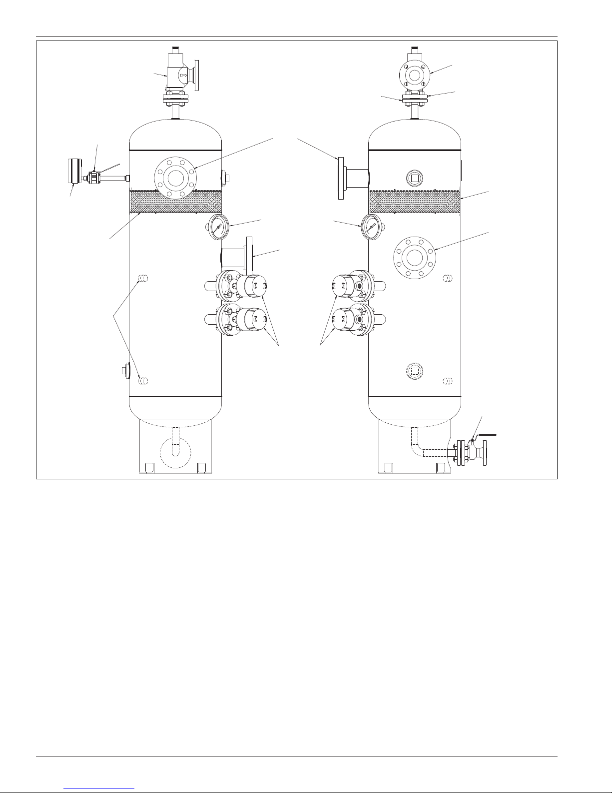
Relief valve
Outlet
2″ 150 lb
Ball valve
Pressure guage
(0–500 PSI)
Stainless steel
demister pad
1/2″ NPT openings
for sight glass
Outlet
3″ 300 lb
Temperature gauge
(0–250 PSI)
Inlet
3″ 300 lb
Liquid level switches
ANSI flange
1″ 300 lb
Inlet
1″ 300 lb
Stainless steel
demister pad
Inlet
3″ 300 lb
Figur e 1.4
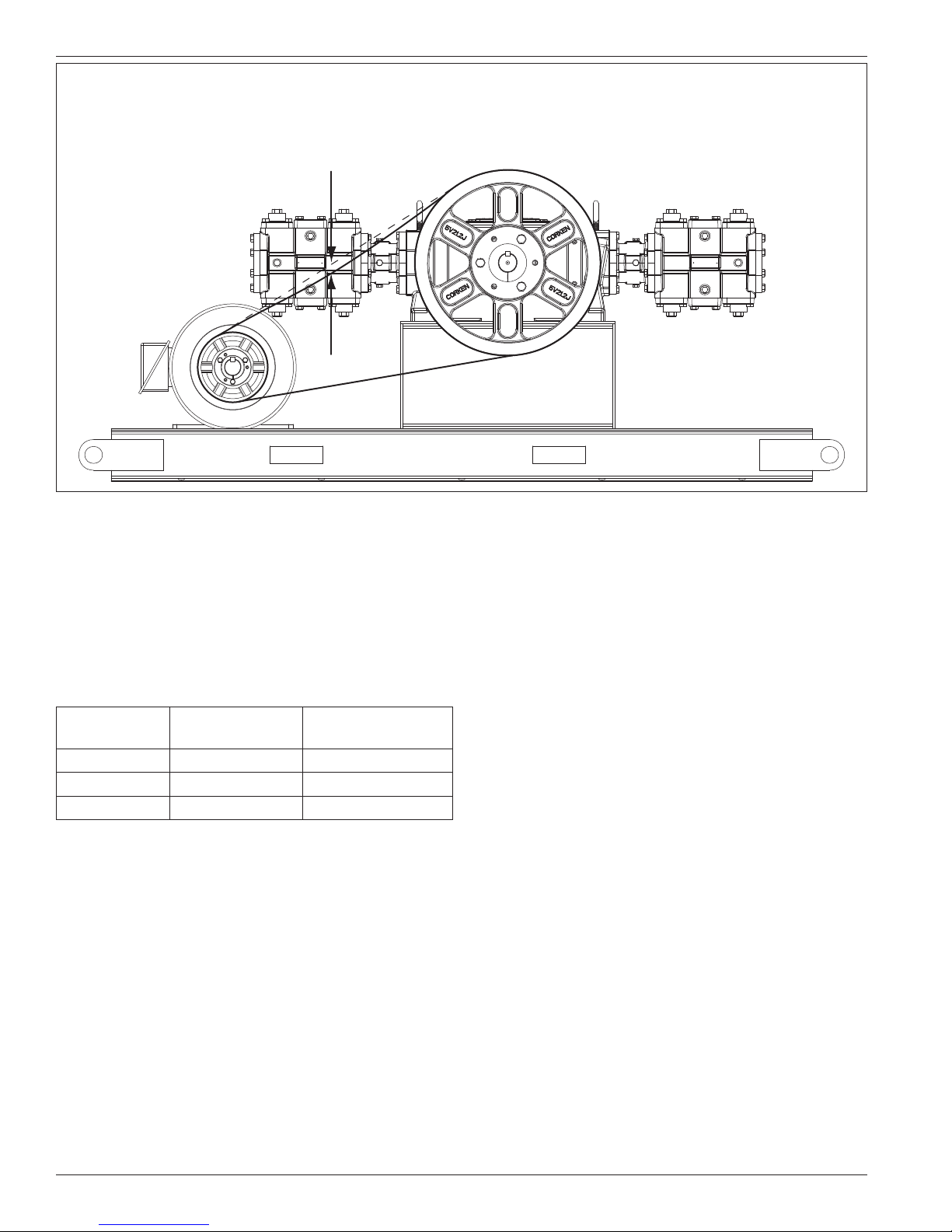
1.5 Driver Installation and Flywheels
Corken compressors may be driven by either electric
motors or internal combustion engines (e.g. gasoline,
diesel, natural gas, etc.). The wiring of an electric
motor is extremely important and must be done by a
competent electrician. Low voltage or improper wiring
of the motor will result in expensive consequences. If
you suspect that you have a low voltage problem, call
your power company.
Humid climates can cause problems with explosion
proof motors. The normal breathing of the motor and
alternating between being warm when running and cool
when stopped can cause moist air to accumulate in
the motor. The moist air inside the motor will condense
and if enough water accumulates, the motor will fail. To
prevent this, make a practice of running the motor at
least once a week on a bright, dry day for an hour or so
without the V-belts. During this period of time, the motor
will heat up and vaporize the condensed moisture.
Manual drain valve
NOTE: No motor manufacturer will guarantee their
explosion proof or totally enclosed (TEFC) motor against
damage from moisture.
Drivers should be selected so the compressor operates
between 400 and 1200 RPM. The unit must not
be operated without the flywheel or severe torsional
imbalances will result that could cause vibration and
a high horsepower requirement. The flywheel should
never be replaced by another pulley unless it has a
higher wk2 value than the flywheel.
NOTE: Never operate a reciprocating compressor
without a flywheel.
For installation with engine drivers, thoroughly review
instructions from the engine manufacturer to assure the
unit is properly installed.
8
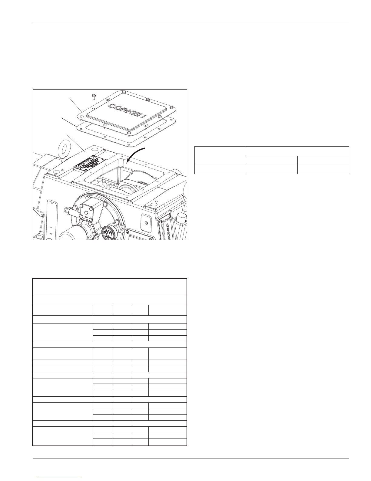
1.6 Crankcase Lubrication
The crankcase of your compressor was drained before
shipment. Before starting the machine, be sure to fill the
crankcase to the full mark on the oil bayonet and not above.
To ensure proper lubrication of the crankcase parts, the
crankcase should be filled through the crankcase inspection
plate (see Fig. 1.6A for the proper oil filling location).
Inspection plate
Inspection plate
gasket
Crankcase
Non-detergent oil is recommended for Corken horizontal
compressors. Detergent oils tend to keep wear particles
and debris suspended in the oil, whereas non-detergent
oils let them settle in the bottom of the crankcase. When
non-detergent oils are not available, detergent oils may
usually be successfully substituted, although compressors
handling ammonia, amine, or imine gases are notable
exceptions. These gases react with the detergent and cause
the crankcase oil to become corrosive and contaminated.
Figure 1.6C shows the recommended oil capacity for the
crankcase. Ensure oil is compatible with the product
being compressed.
Synthetic lubricants are generally not necessary. Please
consult your lubricant supplier if you are considering the
use of synthetic oil.
Fill crankcase
through this opening
Figur e 1.6 A
Use heavy-duty, non-detergent motor oil with rust and
oxidation inhibitors. For viscosity requirements, see
figure 1.6B.
Acceptable Crankcase Oil Products for Corken
Compressors
Constant Weight - Non-Detergent - R&O Inhibited
Oil product ISO VI SAE Ambient Temp.
Exxon®
TERESSTIC 100 95 30 65° - 100° F
68 95 20+ 45° - 70° F
46 95 20 35° - 50° F
Mobil®
RARUS 427 Reciprocating 100 95 30 65° - 100° F
Compressor Oil
DTE Oil Heavy Medium 64 95 20+ 45° - 100° F
Dectol R&O Oil 44 95 20 35° - 50° F
Conoco®
Dectol R&O Oil 100 98 30 65° - 100° F
68 97 20+ 45° - 70° F
46 99 20 35° - 50° F
Texaco®
Regal R&O Oil 100 92 30 65° - 100° F
68 97 20+ 45° - 70° F
46 102 20 35° - 50° F
Sun®
SunVis 900 Oil 100 100 30 65° - 100° F
68 100 20+ 45° - 70° F
46 100 20 35° - 50° F
Figure 1.6B: Oil Selection Chart
Compressor
Model
Approximate Capacity
Quarts Liters
HG/THG600 7 6.6
Figure 1.6C
1.7 Crankcase Oil Pressure
Adjustment
Your Corken compressor is equipped with an
automatically reversible gear type oil pump. It is
essential to ensure the pumping system is primed and
the oil pressure is properly adjusted in order to assure
smooth operation.
Before starting your compressor, check and fill the
crankcase with the proper amount of lubricating oil
(see figure 1.6A for details).
When the compressor is first started, observe the
crankcase oil pressure gauge. If the gauge fails to
indicate pressure within 30 seconds, stop the machine.
Loosen the oil filter and remove the pressure gauge.
Restart the compressor and run it until oil comes out
of the pressure gauge opening or around the filter.
Tighten the filter and reinstall the gauge.
The oil pressure should be about 20 psi (1.4 bars)
minimum for normal service. If the discharge pressure
of the compressor is above 200 psi (14.8 bars), the
oil pressure must be maintained at 25–30 psi (1.7–2.1
bars). A spring-loaded relief valve mounted on the
bearing carrier opposite the flywheel regulates the oil
pressure. As shown in figure 1.7, turn the adjusting
screw clockwise to increase the oil pressure and
counterclockwise to lower it. Be sure to loosen the
adjusting screw locknut before trying to turn the screw
and re-tighten it after making any adjustment (see
figure 1.7 for details).
9
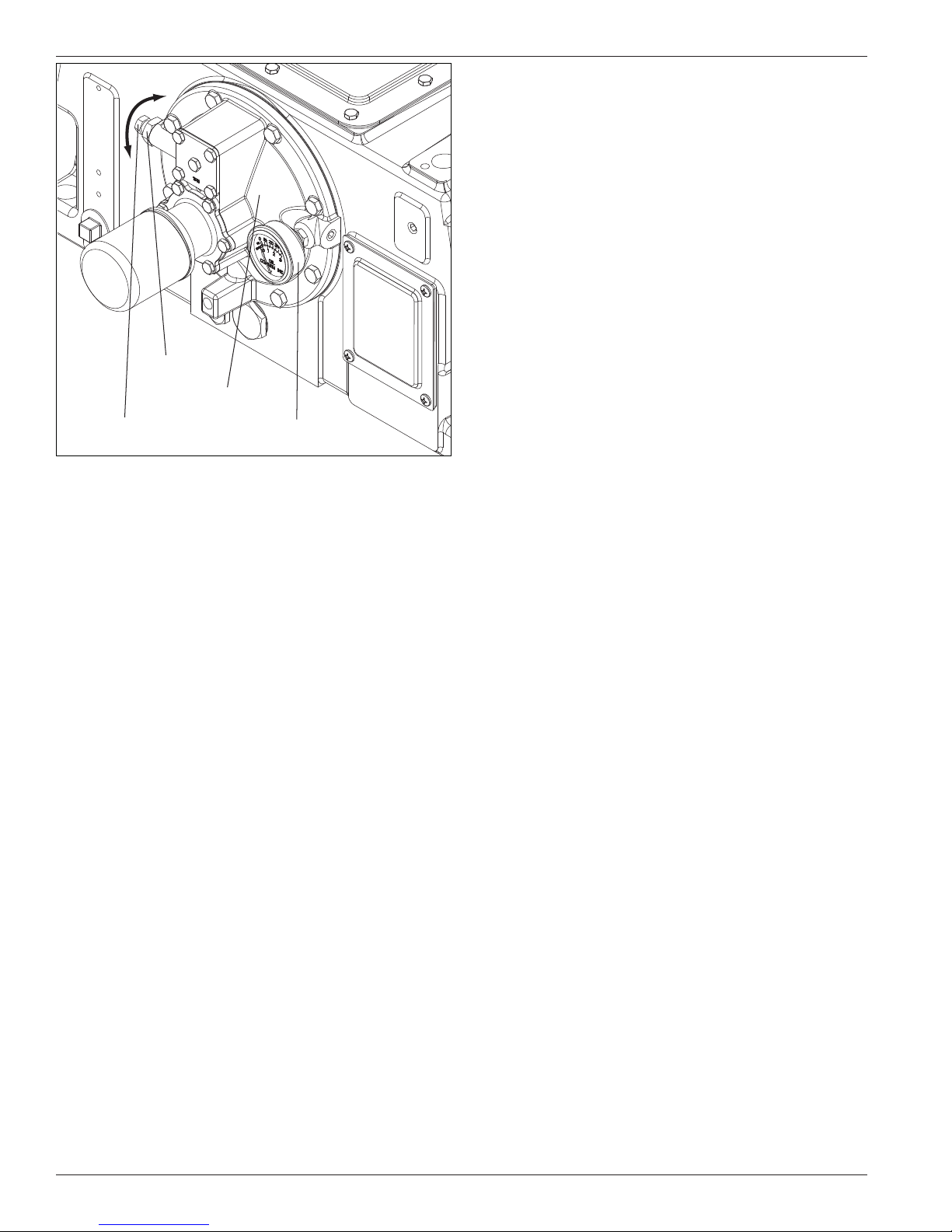
Locknut
the maximum design temperature for the compressor
of 350°F (176°C).
3. Low Suction Pressure Switch: Shuts down the
unit if inlet pressure is not within the preset limit (set
point). In some cases, it is important not to pull a
vacuum because of the potential of pulling oil from the
crankcase into the gas stream.
4. High Discharge Pressure Switch: Shuts down the
unit if the outlet pressure reaches a preset limit (set
point). Both the switch and the compressor have an
operating range. The set point of the pressure switch
should be as follows:
Greater than the normal operating pressure for the
compressor.
Bearing carrier
Oil pressure relief valve
adjustment screw
Oil pressure guage
Figur e 1.7
1.8 Relief Valves
An appropriate relief valve must be installed on
the discharge side of the compressor. On Corken
107C-style mounted units, a relief valve should be
fitted in the piping between the compressor discharge
and the four-way valve. Relief valves should be made of
a material compatible with the gas being compressed.
Local codes and regulations should be checked for
specific relief valve requirements. Also, relief valves
may be required at other points in the compressor’s
system piping.
1.9 Shutdown/Alarm Devices
For many applications, shutdown/alarm switches will
provide worthwhile protection that may prevent serious
damage to your compressor system. All electronic
devices should be selected to meet local code
requirements. Shutdown/alarm devices typically used on
Corken compressors are as follows:
Less than 90% of the relief valve set point pressure.
Less than the maximum operating pressure of the
compressor.
Midpoint of the pressure switch range.
5. Vibration Switch: Shuts down the unit if vibration
becomes excessive. Recommended for units mounted
to a portable skid.
1. Low Oil Pressure Switch: Shuts down the unit if
crankcase oil pressure falls below 12 psi due to oil
pump failure or low oil level in crankcase. The switch
or the compressor controller must have a 30 second
delay on startup which allows the compressor to build
oil pressure in the crankcase.
2. High Discharge Temperature Switch: This switch
is strongly recommended for all applications. Both
the High Discharge Temperature switch (HDT) and
compressor have an operating pressure range. It is
preferable that the switch set point be 30°F (-1°C)
above the normal discharge temperature, but below
10
Chapter 2—Starting Up Your Corken Compressor
The initial operation of your compressor is the most critical
time it will ever face. READ ALL OF CHAPTER TWO BEFORE
YOU PROCEED WITH THE STARTUP CHECKLIST.
2.1 Inspection After Extended
Storage
If your compressor has been out of service for a long
period of time, you should verify that the cylinder bore
and valve areas are free of rust and other debris. For
valve and/or cylinder head removal instructions, refer to
chapter 4 of this IOM manual.
Drain the oil from the crankcase and remove the
crankcase inspection plate. Inspect the running gear for
signs of rust and clean or replace parts as necessary.
Fill crankcase with the appropriate lubricant through the
crankcase inspection plate opening. Squirt oil on the
crossheads and rotate the crankshaft by hand to ensure
that all bearing surfaces are coated with oil.
Rotate unit manually to ensure running gear functions
properly. Replace the crankcase inspection plate and
proceed with startup.
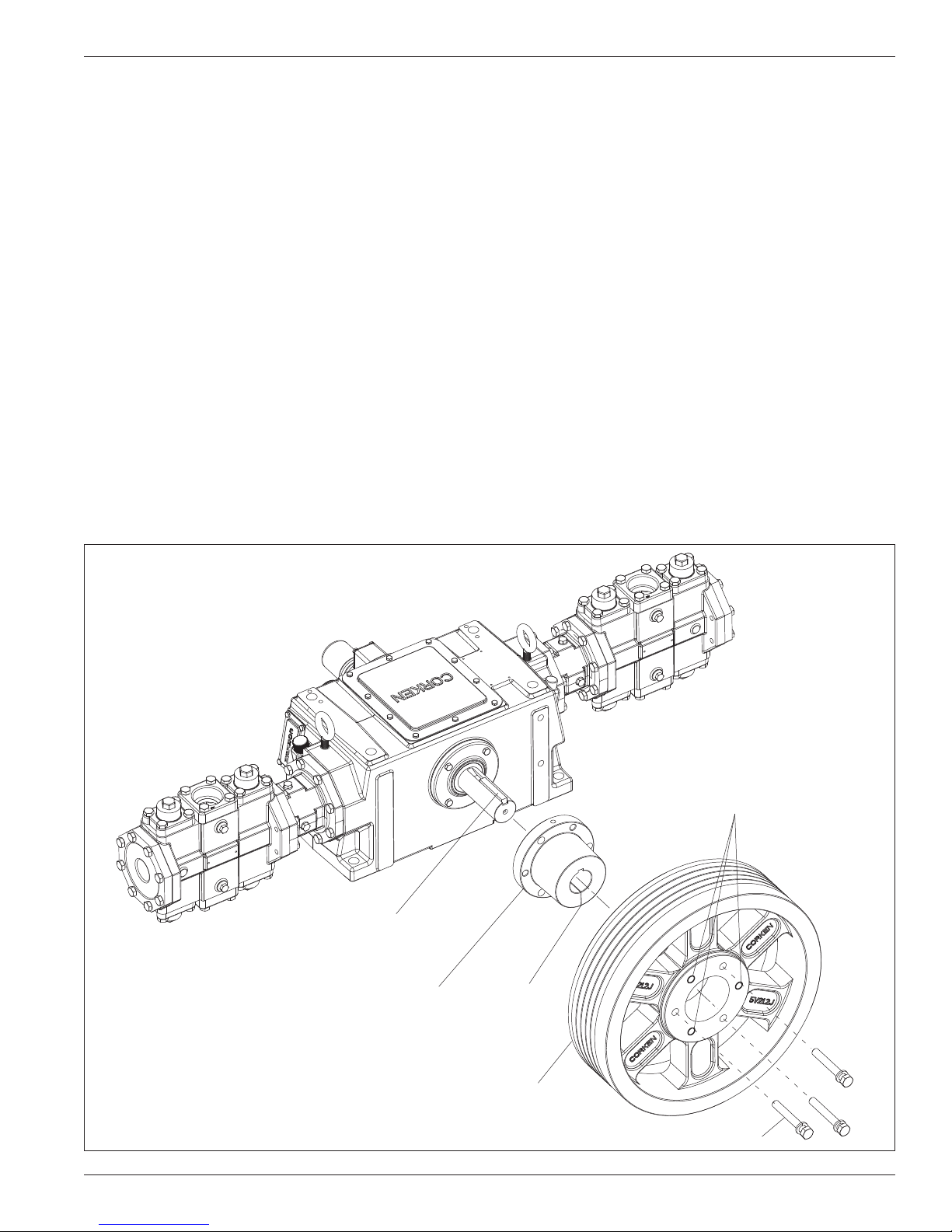
2.2 Flywheel and V-belt Alignment
Before working on the drive assembly, make sure the
electrical power is turned off. Always make sure the
driver and compressor are close enough together to
avoid forcing the belts over the flywheel and sheave.
Tighten the belts so that they are taut, but not extremely
tight. Consult your V Belt supplier for specific tension
recommendations. Belts that are too loose will cause
excessive vibration while those that are too tight may
cause premature bearing failure (refer to figure 2.2C).
Improper belt tension and sheave alignment can cause
vibration, excessive belt wear and premature bearing
failures. Before operating your compressor, check
alignment of the V-grooves of the compressor flywheel
and driver sheave. Visual inspection often will indicate if
the belts are properly aligned, but use of a straight edge
tool or string is the best method.
Crankshaft key
Align hub with crankshaft key.
Flywheel removal holes
(threaded openings)
Split
Flywheel
Tighten flywheel bolts in an even and progressive manner.
Figure 2.2A (model HG601EE (plain style) shown)
11
NOTE:
1) If you are using five individual V-belts, 1/4 to 3/8 inches (6.4 to 9.5 mm) of movement is normal.
2) If you are using five banded V-belts, movement will be much less due to the stiffness of the banded V-belt design.
Figure 2.2C
The flywheel is mounted on the shaft via a split, tapered
hub and three bolts (see figure 2.2A). These bolts should
be tightened in an even and progressive manner to
the specified torque values listed in figure 2.2B. There
must be a gap between the hub and the flywheel when
installation is complete. Failure to do so will cause the
flywheel to be misaligned. Always check the flywheel run
out before startup and readjust if it exceeds the value
listed in Appendix B.
Hub Size
SF 4.625 (11.7) 12–18 (2.5)
E 6.0 (15. 2) 30–36 (4.9)
J 7.25 (18.4) 75–81 (11.1)
Diameter
in. (cm)
Bolt Torque
Ft·lb (kg·meter)
cooling fans can be used to provide additional air flow
across the cylinders.
WATER COOLED: If your unit has water cooled cylinders
(optional), be sure that the cooling system has been
inspected for leaks and proper circulation. Purge air
from the cooling jackets to eliminate air pockets in the
cooling system. If chilled water systems are used be sure
that water shut-off valves are installed to stop water flow
when compressor stops. Monitor system for any signs of
internal sweating. If internal moisture is detected, water
temperatures and flow rates should be checked. Normal
flow rate for cylinders is approximately 1 - 2 gpm.
2.5 Force Feed Cylinder
Figure 2.2B
2.3 Compressor Speed and
Rotation Direction
The lubrication system of the Corken horizontal
compressor is designed to operate at a minimum of 400
RPM. If lower speeds are necessary, consult the factory.
The maximum speed is 1200 RPM. The crankshaft may
be rotated in either direction.
2.4 Compressor Cooling
AIR COOLED: Double acting units generate a lot of
heat around the valve area. It is very important that
the compressor be located where good air flow and
ventilation can be provided. In extreme cases external
Lubrication (Lubed models only)
An external lubricator is bolted directly to the crankcase
and is driven by a chain inside the crankcase at 80%
of crankshaft speed. To ensure each cylinder receives
the same volume of lubrication, an oil divider valve
assembly is also mounted to the opposite end of
the crankcase (see lubricator assembly details in
Appendix D). Since lubricators supplied with Corken
compressors are made by a number of different
manufacturers, refer to the manufacturer’s instructions
provided with the lubricator for specific details on
priming, adjusting and maintaining your lubricator.
Basic operating instructions and flow rate adjustments
are also listed on the side of the lubricator reservoir.
At the initial setup of your compressor, the lubricator
flow should be set to maximum capacity. After the first
hour, reduce the flow to normal operating levels. Normal
12
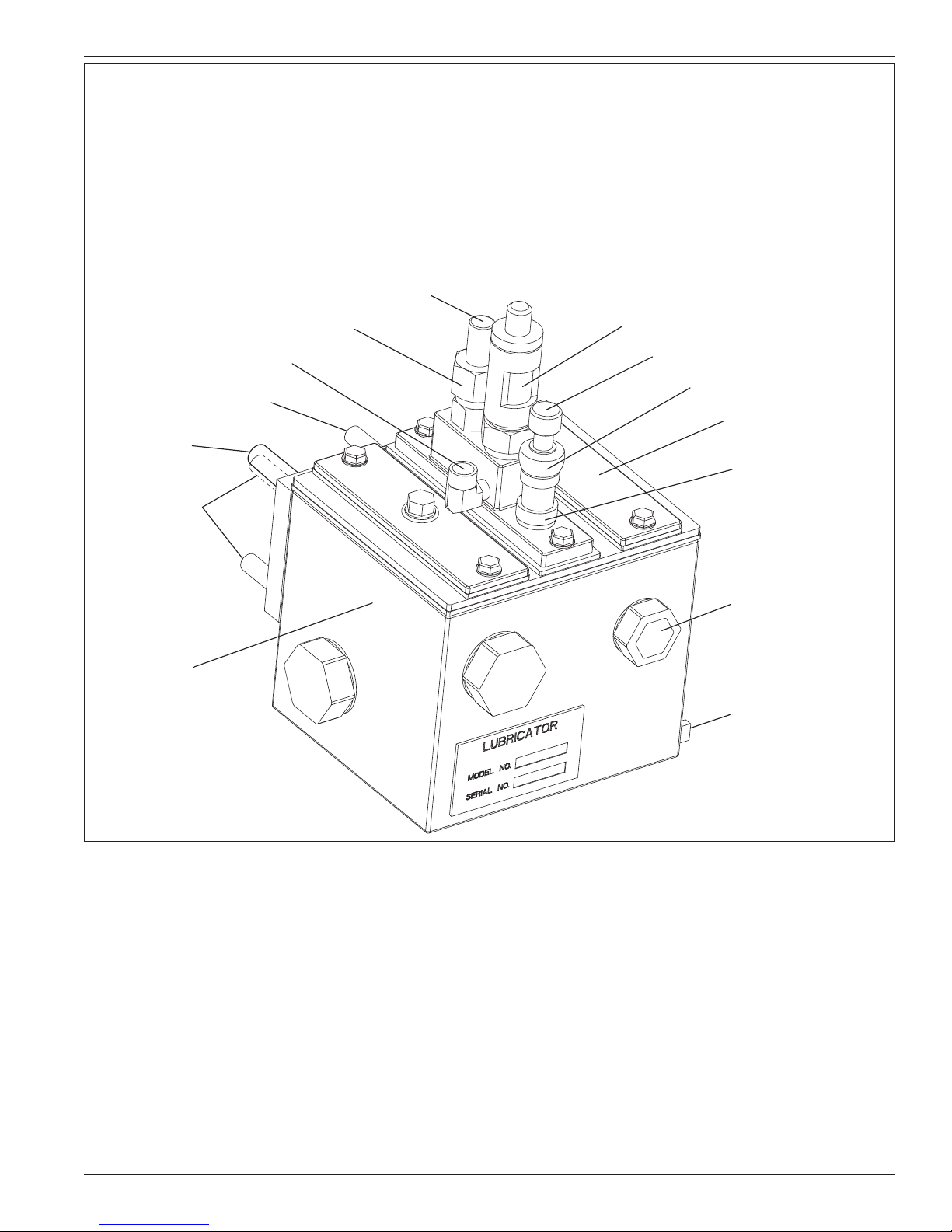
NOTE:
1) Since Corken uses more than one vendor when purchasing lubricators, the lubricator shown below and
respective operational instructions may vary from the one used on your compressor.
2) Operational instructions can be found on the side of the lubricator reservoir.
3) Oil used in the reservoir is for lubricating the internal parts of the lubricator only and not the compressor.
4) Depending on the cylinder size, the oil flow rate for the drip tube site glass is three to six drops per minute
during normal operations.
Oil outlet (1/8″)
Mounting stud
Drive shaft
Mounting studs
Reservoir
Oil inlet (1/8″)
Union nut
Drip tube sight glass
Priming button
Flushing unit
Oil ll opening
Lock nut
Reservoir sight glass
Drain plug
Premier lubricator model number P-55U with pump no. 91490 shown above.
operating levels range from three to six drops per minute
depending upon the cylinder size.
NOTE: The lubricator supplied on your CORKEN
compressor must be supplied with oil from an external
supply tank and NOT from the compressor crankcase or
lubricator reservoir.
Oil types: Refer to section 1.6 (crankcase lubrication).
2.6 Variable Clearance Heads (VCH)
Variable clearance head (VCH) assemblies (outboard)
allow adjustment of the compressor when operating
conditions change. By turning the clearance volume
adjusting cup, you can easily change the capacity
and bhp requirements of the cylinder. Normally, the
packager will have already provided at least a preliminary
adjustment of the VCH. If not, you may wish to adjust
the heads for maximum clearance before startup. After
startup, adjust the heads inward to increase the capacity
and bhp of the cylinder to the desired levels.
To adjust the variable clearance heads, follow the steps
below.
1) Remove the VCH adjusting screw nut. Adjustment can
be made while the unit running.
2) Turn the end of the adjusting cup to adjust the cylinder
head end clearance.
13

3) Turning the end of the adjusting cup inward (clockwise)
reduces cylinder head end clearance.
4) Turning the end of the adjusting cup outward
(counterclockwise) increases cylinder head end
clearance.
17. Carefully check for any loose connections or bolts.
18. Remove all stray objects (rags, tools, etc.) from
vicinity of the unit.
19. Confirm all valves are open or closed as required.
5) Replace the VCH adjustable screw nut and O-ring.
The approximate clearance volume change per turn of
the adjusting bolt is 3%.
2.7 Startup Check List
Please verify each item on this list below before starting
your compressor! Failure to do so may result in a costly
and/or dangerous mistake.
Before Starting the Compressor
1. Become familiar with the function of all piping
associated with the compressor. Know each line’s use!
2. Make certain actual operating conditions will match
the anticipated conditions.
3. Ensure line pressures are within cylinder pressure
ratings.
4. Clean out all piping.
5. Ensure all adapter and distance piece openings are
tubed or plugged as desired.
6. Check all mounting shims, cylinder and piping supports
to ensure that no twisting forces or other undesired
nozzle forces or torque is applied to the compressor.
7. Make certain strainer elements are in place and clean.
20. Re-check all of the above.
After Starting Compressor
1. Verify and note proper oil pressure. Shut down and
correct any problems immediately.
2. Observe noise and vibration levels. Correct
immediately if excessive.
3. Verify proper compressor speed.
4. Examine entire system for gas or oil leaks.
5. Note rotation direction.
6. Check start-up voltage drop, running amperage
and voltage.
7. Verify proper lubrication rate (lubed units only).
8. Test each shutdown device and record set points.
9. Test or confirm set point on all relief valves. Test all
dump valves, relief valves and unloaders.
10. Check and record all temperatures and pressures
after 30 minutes and 1 hour. Retain records for
future reference.
11. After approximately one hour of running time, tighten
all head bolts, valve holddown bolts, and baseplate
bolts. See Appendix B for torque values.
8. Make certain cylinder bore and valve areas are clean.
9. Check V-belt tension and alignment or drive alignment
on direct drive units.
10. Rotate unit by hand and make certain there is no
wobble or play in the flywheel or sheave.
11. Check crankcase oil level.
12. Drain all liquid traps, separators, etc.
13. Verify proper electrical supply to motor and panel.
14. Check all gauges and confirm a zero level reading.
15. Test piping system for leaks.
16. Purge unit of air before pressurizing with gas. Follow
your company procedures for this operation.
14

Chapter 3—Routine Maintenance Chart
Item to Check Daily Weekly Monthly
Six
Months
Yearly
Crankcase oil pressure
Compressor discharge pressure
Overall visual check
Crankcase oil level
Drain liquid from accumulation points
3
2 2
Drain adapters and distance pieces
Clean cooling surfaces on compressor and intercooler (if any)
Lubricator supply tank level (if any)
Check belts for correct tension
Inspect valve assemblies
Lubricate motor bearings in accordance with manufacturers’
recommendations
Inspect motor starter contact points
Inspect piston rings
1
Piston ring life varies greatly, depending on application, gas and operating pressures. Consult factory for additional recommendations for your
specific application.
2
Change oil ever y 2,200 hours of operation or every 6 months, whichever occurs first. If the oil is unusually dirty, change it as often as needed
to maintain a clean oil condition. Change replacement filter 4225 with every oil change.
3
Liquid traps should be drained prior to star tup.
1
1 1
Chapter 4—Routine Service and Repair Procedures
CAUTION: Always relieve pressure in the unit before
attempting any repairs. After repair, the unit should
be pressure tested and checked for leaks at all joints
and gasket surfaces.
If routine maintenance is performed as listed in chapter
3, repair service on your Corken gas compressor is
generally limited to replacing valves or piston rings.
When it comes time to order replacement parts, be sure
to consult the part details appendix in the back of this
Installation, Operation & Maintenance (IOM) manual for a
complete list of part numbers and descriptions.
4.1 Compressor Valves
Test the compressor valves by closing the inlet piping
valves while the unit is running; however, do not allow
the machine to operate in this way very long. If the inlet
pressure gauge does not drop to zero almost immediately,
one or more of the compressor valves is probably damaged
or dirty. However, it is possible for the pressure gauge itself
to be faulty.
cover plates to each other. If a valve or gasket is leaking,
it will have a higher operating temperature. NOTE: This
method will not be suitable for two stage compressors if
each stage does not have more than one valve.
Each suction and/or discharge valve assembly is easily
removed as a unit for inspection. If any part of the
valve assembly is broken, the valve assembly should be
replaced. See valve assembly parts details in the Appendix
D for a complete list of part numbers and descriptions.
If a compressor valve is leaking due to dirt or any other
foreign material that keeps the valve plate and seat from
sealing, the valve may be cleaned and reused. New gaskets
and/or O-rings should be used to ensure a good seal.
The valve holddown components and valve assemblies
listed in Appendix D show the various specifications
used on horizontal compressors. Since more than one
suction valve arrangement is available for each model of
compressor, it is necessary to know your complete model
number so you can identify the valve type specification
number (see example listed below).
In most cases, if a compressor valve or valve gasket
is leaking, it will create more heat. On a single stage
compressor, you may be able to compare the operating
temperatures of the two suction or discharge valves and
Model number THG601BBGM 4 FBANSNNN
Valve type = spec 4
15

Valve Inspection and/or Replacement
Before removing and inspecting the valves, begin by
depressurizing and purging (if necessary) the unit and
refer to Appendix D.
Disassembly of 2.75" Cylinder Size
1. Remove the valve cover plate and O-ring by removing
each of the three bolts.
replaced. Replacement is usually preferable although
repair parts are available. If valve plates are replaced,
seats should also be lapped until they are perfectly
smooth. If more than .005 of an inch must be removed
to achieve a smooth surface, the valve should be
discarded. If plates are replaced without re-lapping
the seat, rapid wear and leakage may occur.
Assembly of 3.25", 4", 5", 6" and 8" Cylinder Sizes
2. After the cover plate and O-ring have been removed,
the valve assembly and valve gasket can be lifted out.
3. Inspect valves for breakage, corrosion, debris and
scratches on the valve plate. In many cases, valves
may simply be cleaned and reinstalled. If the valves
show any damage, they should be repaired or
replaced. Replacement is usually preferable although
repair parts are available. If valve plates are replaced,
seats should also be lapped until they are perfectly
smooth. If more than .005 of an inch must be removed
to achieve a smooth surface, the valve should be
discarded. If plates are replaced without re-lapping
the seat, rapid wear and leakage may occur.
Assembly of 2.75" Cylinder Size
1. Insert metal valve gasket into the suction and/or
discharge opening of the head. The metal valve
gasket should always be replaced when the valve
is reinstalled.
2. Insert cleaned or new valve assembly. Make sure the
suction and discharge valves are in the proper suction
and discharge opening in the head.
3. Replace the O-ring and valve cover plate. Torque the
bolts to the value listed in Appendix B. CAUTION: Be
sure the holddown screw has been removed. NOTE:
Gaskets and O-rings are not normally reusable.
4. Check bolts after first week of operation. Re-torque if
necessary. See Appendix B for torque values.
Disassembly of 3.25", 4", 5", 6" and 8" Cylinder Sizes
1. Unscrew the valve cap and remove the O-ring.
2. Remove the valve cover plate, O-ring and holddown
screw by removing each of the four bolts. The
holddown screw is easily removed with the special
wrench supplied with your compressor.
3. After the cover plate and O-ring have been removed,
the valve cage, valve assembly and valve gasket can
be lifted out.
4. Inspect valves for breakage, corrosion, debris and
scratches on the valve plate. In many cases, valves
may simply be cleaned and reinstalled. If the valves
show any damage, they should be repaired or
1. Insert metal valve gasket into the suction and/or
discharge opening of the head. The metal valve
gasket should always be replaced when the valve is
reinstalled.
2. Insert cleaned or new valve assembly. Make sure the
suction and discharge valves are in the proper suction
and discharge opening in the head.
3. Insert the valve cage.
4. Replace the O-ring and valve cover plate. Torque the
bolts to the value listed in Appendix B. CAUTION: Be
sure the holddown screw has been removed.
5. To ensure the valve gasket is properly seated, insert
the holddown screw and tighten to the value listed
in Appendix B. NOTE: Gaskets and O-rings are not
normally reusable.
6. Replace the O-ring and valve cap and tighten to the
value listed in Appendix B.
7. Check bolts and valve holddown screws after first
week of operation. Re-torque if necessary. See
Appendix B for torque values.
4.2 Heads
A horizontal compressor cylinder head or adjusting cap
seldom require replacement if the compressor is properly
maintained. The primary cause of damage to a cylinder
head and adjusting cap is corrosion and the entry of
solid debris or liquid into the compression chamber.
Improper storage can also result in corrosion damage to
the cylinder heads and adjusting caps (for proper storage
instructions see chapter 5).
Many compressor repair operations require removal
of the cylinder heads and adjusting caps. While the
compressor is disassembled, special care should be
taken to avoid damage or corrosion. If the compressor
is to be left open for more than a few hours, bare metal
surfaces should be coated with rust preventative.
When reassembling the compressor, make sure the
bolts are re-tightened to the torque values listed in
Appendix B.
16
4.3 Piston Rings and Piston Ring
Expander Replacement
4. Remove the lock nut, washer and shims and pull the
piston off the end of the piston rod. Keep track of which
piston washer and shims came out of each cylinder.
Piston Ring Life - Dry Cylinder Compressor Applicat ions
It is unrealistic to expect the same piston ring life from
a dry cylinder compressor as from a lubricated cylinder
machine because the PTFE rings have greater wear,
particularly under high temperature conditions.
CORKEN uses one of the best PTFE ring formulations
available. The normal life expectancy is approximately
2,200 hours of continuous service within recommended
compression ratios. However, ring life will vary considerably
depending upon piston speed (RPM), ambient temperature,
intermittent service conditions, compression ratio and the
nature of the gas being handled.
The secret to long ring life is operating at a low temperature.
A low ambient temperature and compression ratio along
with better intercooling will provide better ring wear.
Piston Ring Life - Lubricated Cylinder
Compressor Applications
If your compressor is equipped with cylinder lubrication
you can expect considerably longer life from your piston
rings than the dry cylinder units described above.
Piston ring life will vary considerably from application to
application. Ring life will improve dramatically at lower
speeds and temperatures.
Piston and Piston Ring Expander Replacement
1. To replace the piston rings, depressurize the
compressor and purge if necessary.
2. Remove the cylinder cap (if any) and head.
3. Loosen the piston cap screws and remove the piston
cap as shown in figure 4.3 by pinching two loose
screws together.
5. Piston rings and expanders may then be easily
removed and replaced. Corken recommends replacing
expanders whenever rings are replaced. To determine
if rings should be replaced, measure the radial
thickness and compare it to the chart in Appendix B.
4.4 Pistons
As you read the following instructions, refer to
Appendix D for parts details.
1. To replace the pistons, depressurize the compressor
and purge if necessary.
2. Remove the head (or adjusting screw nut, cylinder
cap, adjusting cup and head - applies to adjustable
head configuration only) as shown in Appendix D.
3. Remove the piston cap and shims by loosening and
removing the piston cap screws holding the piston cap
to the piston. Re-insert two loose screws as shown
in figure 4.3. Using your fingers, pinch the screws
together and pull the piston cap out of the cylinder.
4. Remove the lock nut and thrust washer and pull the
piston out of the cylinder. Then, remove the thrust
washer and shims on the end of the piston rod.
5. Check the thrust washer and shims for damage and
replace if necessary.
6. Measure the thickness of the existing shims.
7. Insert one thrust washer against piston rod shoulder
followed by the same shims (or the same thickness of
shims) as before.
8. Before installing the piston, attach the piston ring
expanders and piston rings to the piston. Then, install
the piston on the piston rod.
Figure 4.3
9. Install a thrust washer and lock nut and tighten the
lock nut to the value listed in Appendix B.
10. Now remove an inboard valve and measure dimension
“Y” on the inboard end of the piston as shown in
Appendix B. If this measurement does not fall within
the tolerances listed in the piston assembly details
(Appendix B), remove the piston and adjust the shims
as necessary. Re-install the piston and tighten the
lock nut to the value listed in Appendix B. Re-measure
the “Y” dimension.
11. After the “Y” dimension is within tolerance, install
the piston cap with the same shim/shims (or same
thickness of shims) as before.
17

12. Torque the piston cap screws to the value listed in
Appendix B.
13. Install the head (or head and adjustable cap applies to adjustable head configuration only) as
show in Appendix D. Torque bolts to the value listed
in Appendix B.
14. Now remove an outboard valve and measure
dimension “X” at the outboard end of the piston as
shown in the Appendix B. If this measurement does
not fall within the tolerances in Appendix B, remove
the head (or head and adjustable cap - applies to
adjustable head configuration only) and piston cap
and adjust the shims as necessary. Re-install the
piston cap and tighten the piston cap screws in an
alternating sequence to the values listed in Appendix
B. Re-install the head (or head and adjustable cap
- applies to adjustable head configuration only) and
torque to the value listed in Appendix B. Re-measure
the “X” dimension again.
15. After the “X” dimension is within tolerance, remove
the adjustable cap and install the adjustable cup
followed by the adjustable cap and adjustable screw
nut as shown in Appendix D.
16. Torque the bolts in an alternating sequence to the
values listed in Appendix B.
17. Replace the previously removed valves. Best results
will be obtained if new valve gaskets are used.
18. Follow standard startup procedures.
1) Keep foreign material out of crosshead bore on
crankcase. Wipe inside of bore with clean rag and
coat bore with oil.
2) Inspect piston rod for cleanliness and coat with oil
before assembly.
3) Before installing adapter and packing cartridge
on piston rod, install packing installation cone
(Corken #3905) over piston rod threads. This
will aid and protect packing during installation.
Failure to use this packing cone could result in
packing damage. Refer to Appendix D for correct
installation of packing.
4) Rotate flywheel/crankshaft by hand several revolutions
to ensure proper fit of all assembled parts.
5) Orient cylinder inlet and outlet to piping installation
to ensure proper valve alignment with system.
Valves must be properly oriented with suction and
discharge piping.
6) For piston installation instructions, see section 4.4.
7) After installing the piston, again, rotate flywheel/
crankshaft by hand several revolutions to ensure
proper fit of all assembled parts.
8) Check crankcase for proper oil level.
9) See start-up procedure in section 2.7. During startup, listen to the compressor for any unusual noises.
If any problems arise during assembly, please
contact the factory.
4.5 Cylinder Replacement
Cylinders very seldom require replacement if the
compressor is properly maintained. The primary cause
of damage to cylinders is corrosion and the entry of solid
debris or liquid into the compression chamber. Improper
storage can also result in corrosion damage to cylinder
(for proper storage instructions see chapter 5). Damage
can also occur if the piston rings are allowed to wear so
much that the ring expander can reach the cylinder wall.
Many compressor repair operations require removal of
the cylinder. While the compressor is disassembled,
special care should be taken to avoid damage or
corrosion to the cylinder. If the compressor is to be left
open for more than a few hours, bare metal surfaces
should be coated with rust preventative.
If the cylinder does become damaged or corroded, use
a hone to smooth the cylinder bore and then polish it
to the value shown in Appendix B. If more than .005 of
an inch must be removed to smooth the bore, replace
the cylinder. Cylinder liners and oversized rings are not
available. OVERBORING THE CYLINDER WILL RESULT
IN GREATLY REDUCED RING LIFE.
When reassembling the compressor, make sure the
bolts are retightened using the torque values listed in
Appendix B.
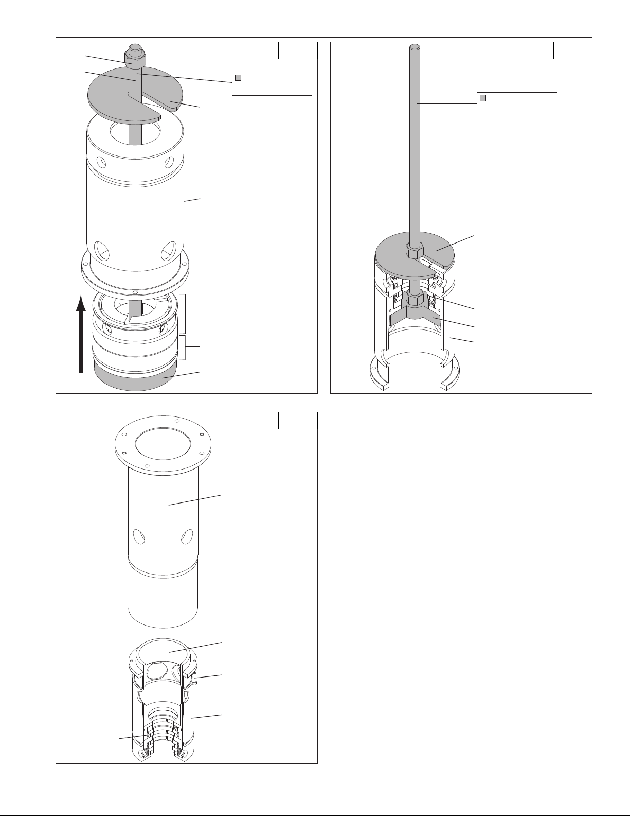
4.6 Packing Replacement
Instructions
Caution: Before installing the new piston rod packing,
bleed all pressure from the compressor and piping and
purge if necessary. After the new piston rod packing has
been installed, the unit should be pressure tested and
checked for leaks at all joints and gasket surfaces. When
the compressor is being used with toxic, dangerous,
flammable or explosive gases, this pressure and leak
testing should be done with air or a dry, inert gas such
as nitrogen.
For specific construction details and actual part numbers,
consult Appendix D in the back of this Installation,
Operation & Maintenance (IOM) manual. Use instructions
below that apply to the MODEL and SERIAL NUMBER of
your compressor.
18

Cleanliness:
Sealing a reciprocating piston rod is a very difficult task.
In order to create the best seal possible between the
piston rod and the packing, KEEP YOUR HANDS, PARTS
AND TOOLS CLEAN DURING INSTALLATION.
Workmanship:
Your Corken compressor is a precision piece of equipment
with very close tolerances. Treat it as such. Never beat
on it to get parts in or out.
Disassembly of Packing—Plain-style Compressor
Models HG601 and HG602
1. Depressurize and open the compressor before
performing any tasks.
2. Remove the head (along with adjustable head
components, if any), pistons and cylinder.
3. Standard Packing Specification
a. Refer to Appendix D for your particular model of
compressor and note the order in which the parts
are removed.
b. Mark the top of the packing cartridge body to
facilitate later reassembly. Remove the four socket
head bolts that attach the packing cartridge
assembly to the adapter. It is not normally necessar y
to remove the adapter from the crankcase in order
to disassemble or reassemble the packing.
c. Partially insert the bolts in the puller holes in the
outer end of the packing cartridge body and pull
outward to remove the entire packing cartridge
assembly from the adapter and over the piston
rod. If the packing cartridge assembly does not
slide out easily, it may be necessary to alternately
turn the bolts clockwise in the puller holes so
that the bolts engage the adapter and force the
packing cartridge assembly to come out.
d. Remove the outer retainer ring, solid packing breaker
(not included on 6" and 8" cylinders), packing cups,
all packing sets, backup rings, etc. from the cylinder
side of the packing cartridge body.
e. Remove the inner retainer ring, packing washer
and oil wiper ring set from the crankcase side of
the packing cartridge body.
head bolts that attach the packing cartridge cap
to the adapter. It is not normally necessary to
remove the adapter from the crankcase in order to
disassemble or reassemble the packing.
c. Partially insert the bolts in the puller holes in the
outer end of the packing cartridge cap and pull
outward to remove the packing cartridge cap from
the rest of the packing cartridge assembly, adapter
and over the piston rod. If the packing cartridge
cap does not slide out easily, it may be necessary
to alternately turn the bolts clockwise in the puller
holes so that the bolts engage the adapter and
force the packing cartridge cap to come out.
d. Mark the top of the packing cartridge body to
facilitate later reassembly and proper alignment
with the packing cartridge cap. Pull outward to
remove the packing cartridge assembly from the
adapter and piston rod.
i. 2-3/4" and 3-1/4" Cylinders: Using a pair
of flat-bladed screwdrivers or similar tools,
engage the annular groove on the outer end
(cylinder side) of the packing cartridge body
and pry the packing cartridge assembly from
the adapter and over the piston rod.
ii. 4", 5", 6" and 8" Cylinders: Partially insert
the bolts in the puller holes in the outer end of
the packing cartridge body and pull outward
to remove the packing cartridge assembly
from the adapter and over the piston rod. If the
packing cartridge assembly does not slide out
easily, it may be necessary to alternately turn
the bolts clockwise in the puller holes so that
the bolts engage the adapter and force the
packing cartridge assembly to come out.
e. In addition to the packing cartridge cap previously
removed, remove the solid packing breaker (not
included on 6" and 8" cylinders), packing cups,
all packing sets, backup rings, purge packing
cups, cup spacer, packing spacer, oil wiper cup,
oil wiper ring set, etc. from the cylinder side of the
packing cartridge body.
Assembly of Packing—Plain-style Compressor
Models HG601 and HG602
1. Always use new O-rings, packing and oil wiper ring
sets during assembly.
4. Purge Packing Specification
a. Refer to Appendix D for your particular model of
compressor and note the order in which the parts
are removed.
b. Mark the top of the packing cartridge cap to
facilitate later reassembly. Remove the four socket
2. Clean packing cartridge body and parts removed
from it during disassembly process.
3. Standard Packing Specification
a. Refer to Appendix D and note the order in which the
parts are to be installed and their correct orientation.
19

b. Install the oil wiper ring set, packing washer and
inner retainer ring into the crankcase side of the
packing cartridge body.
c. Install the O-ring on the packing spacer, and
install both into the cylinder side of the packing
cartridge body.
d. Install a back-up ring, segmented packing set
(tangent-tangent [TT]) and packing cup with
O-ring into the cylinder side of the packing
cartridge body.
e. Install a back-up ring, a segmented packing set
(radial-tangent [RT]) and packing cup with O-ring
into the cylinder side of the packing cartridge
body. Repeat this process for the remaining RT
packing sets.
f. Install the pressure breaker ring (not included
on 6" and 8" cylinders) and final packing cup
with O-ring into the cylinder side of the packing
cartridge body. Reinstall outer retainer ring.
g. Install a packing installation cone (Part no. 3905)
on threaded end of the piston rod
h. Install a new O-ring inside the adapter.
i. Carefully install the assembled packing cartridge
assembly on the piston rod and insert into the
adapter. Be sure the mark previously made on the
packing cartridge body is oriented up because the
packing cartridge body can only be installed in
one position. Attach the packing cartridge body to
the adapter with the four socket head bolts.
j. Remove the packing installation cone.
k. Replace the cylinder, pistons and cylinder head
(along with adjustable head components, if any).
l. Rotate the unit by hand to insure proper assembly.
4. Purge Packing Specification
a. Refer to Appendix D and note the order in which the
parts are to be installed and their correct orientation.
b. Install oil wiper ring set and oil wiper ring cup into
the cylinder side of the packing cartridge body.
c. Install a biased packing set (tangent-tangent with
springs toward cylinder [TTs]), purge packing
cup with O-ring and cup spacer into the cylinder
side of the packing cartridge body. NOTE: The
6 springs in the biased packing sets are very
small and fit loosely, so extra care is needed to
keep from losing them or having them become
dislodged during assembly.
d. Install a purge packing cup with O-ring and biased
packing set (tangent-tangent with springs toward
crankcase [sTT]) into cylinder side of packing
cartridge body.
e. Install the O-ring on the packing spacer, and
install both into the cylinder side of the packing
cartridge body.
f. Install the back-up ring, segmented packing set
(tangent-tangent [TT]) and packing cup with
the O-ring into the cylinder side of the packing
cartridge body.
g. 2-3/4", 3-1/4" and 4" Cylinders: Each of these
cylinder sizes includes a pressure breaker ring
on the outer end of the packing cartridge
assembly. Also, these cylinder sizes include a
packing cartridge cap into which at least some
of the segmented packing sets (radial-tangent
[RT]) are positioned.
i. Install a back-up ring, segmented packing
set (radial-tangent [RT]) and packing cup with
O-ring into cylinder side of packing cartridge
body. Repeat this process as necessary for
additional RT packing sets until a packing cup
extends partially from the cylinder side of the
packing cartridge body.
ii. Install the pressure breaker ring and packing
cup with O-ring into the packing cartridge cap.
iii. Install a back-up ring, segmented packing
set (radial-tangent [RT]) and packing cup with
O-ring into the packing cartridge cap. Repeat
this process for remaining RT packing sets.
iv. Install the packing cartridge cap on the packing
cartridge body, making sure the previouslymade markings on each are aligned. The
portion of the packing cup extending from the
packing cartridge body should extend into the
packing cartridge cap.
v. Insure that the pin extending from the outer
end of packing box cartridge fits into the
corresponding hole in the packing cartridge
cap. NOTE: Some early models did not have
this pin.
h. 5", 6" and 8" Cylinders: Each of these cylinder sizes
includes a flat packing cartridge cap that fits on the
outer end of the packing cartridge body.
i. Install a back-up ring, segmented packing
set (radial-tangent [RT]) and packing cup with
O-ring into the cylinder side of the packing
cartridge body. Repeat this process for
remaining RT packing sets.
20

ii. Position the packing cartridge cap on the
packing cartridge body, making sure the
previously-made markings on each are aligned.
The holes in the packing cap should be aligned
with the corresponding holes in the packing
cartridge body.
i. Install a packing installation cone (Part no. 3905)
on threaded end of the piston rod
j. Install a new O-ring inside the adapter.
k. Carefully install the assembled packing cartridge
assembly with packing cartridge cap on the piston
rod and insert into the adapter. Be sure the marks
previously marked on the packing cartridge body
and cap are oriented up because most packing
cartridge bodies can only be installed in one
position. Attach the packing cartridge cap to the
adapter with the four socket head bolts.
l. Remove the packing installation cone.
m. Replace the cylinder, pistons and cylinder head
(along with adjustable head components, if any).
cartridge assembly from the adapter and over the
piston rod.
a. 2-3/4" and 3-1/4" Cylinders: Using a pair of flat-
bladed screwdrivers or similar tools, engage the
annular groove on the outer end (cylinder side) of the
packing cartridge body and pry the packing cartridge
assembly from the adapter and piston rod.
b. 4", 5", 6" and 8" Cylinders: Partially insert the
bolts in the puller holes in the outer end of the
packing cartridge body and pull outward to remove
the packing cartridge assembly from the adapter
and over the piston rod. If the packing cartridge
assembly does not slide out easily, it may be
necessary to alternately turn the bolts clockwise
in the puller holes so that the bolts engage the
adapter and force the packing cartridge assembly
to come out.
7. Separate the packing cartridge adapter from the
packing cartridge body by removing the four small
socket head screws. Remove the cup spacer by
sliding it out of the packing cartridge body or packing
cartridge adapter.
n. Rotate the unit by hand to insure proper assembly.
Disassembly of Packing—T-style Compressor
Models THG601 and THG602
1. Depressurize and open the compressor before
performing any tasks.
2. Remove the head (along with adjustable head
components, if any), pistons and cylinder.
3. Refer to Appendix D for your particular model of
compressor and note the order in which the parts
are removed.
4. Mark the top of the packing cartridge cap to facilitate
later reassembly. Remove the four socket head bolts
that attach the packing cartridge cap to the adapter.
It is not normally necessary to remove the adapter
from the distance piece or the distance piece from
the crankcase in order to disassemble or reassemble
the packing.
5. Partially insert the bolts in the puller holes in the outer
end of the packing cartridge cap and pull outward
to remove the packing cartridge cap from the rest of
the packing cartridge assembly, adapter and over the
piston rod. If the packing cartridge cap does not slide
out easily, it may be necessary to alternately turn the
bolts clockwise in the puller holes so that the bolts
engage the adapter and force the packing cartridge
cap to come out.
6. Mark the top of the packing cartridge body to facilitate
later reassembly. Pull outward to remove the packing
8. Outer Packing
a. In addition to the packing cartridge cap previously
removed, remove solid packing breaker (not
included on 6" and 8" cylinders), packing cups,
packing sets, backup rings, packing spacer and
purge packing cup, etc. from the cylinder side of
the packing cartridge body.
b. If the packing components are not easily removable,
it may be necessary to use Corken Packing Removal
Tool 4789-X. Referring to Figure 4.6A, orient the
packing cartridge body so that the open end
(cylinder side) faces down, and align the tool with
the center opening of the packing cartridge.
c. Insert Tool 4789-X into the packing cartridge body
until the engagement end of the tool is just above
the purge packing cup. See Figure 4.6B.
d. Press the spring-loaded lever inward so that the
engagement end of the lever moves outward. While
still holding the lever in, place the engagement
ends of the tool and lever in contact with the purge
packing cup, and use a hammer or similar device
to drive the outer packing set from the packing
cartridge body.
9. Middle Packing: Remove the packing cups, packing
sets, backup rings, packing spacer and purge packing
cup, etc. from the crankcase side of the packing
cartridge body. If necessary Packing Removal Tool
4789-X may be used to remove the middle packing
set in a manner similar to the outer packing set.
21
Lever
Engagement end of tool
Step 1 Step 2
Packing removal
tool (4789-X)
Engagement end of lever
Packing cartride body
Packing removal
tool (4789-X)
Push lever in to actuate
Purge packing cup
Purge packing cup
Figure 4.6A: Packing disassembly Figure 4.6B: Packing disassembly
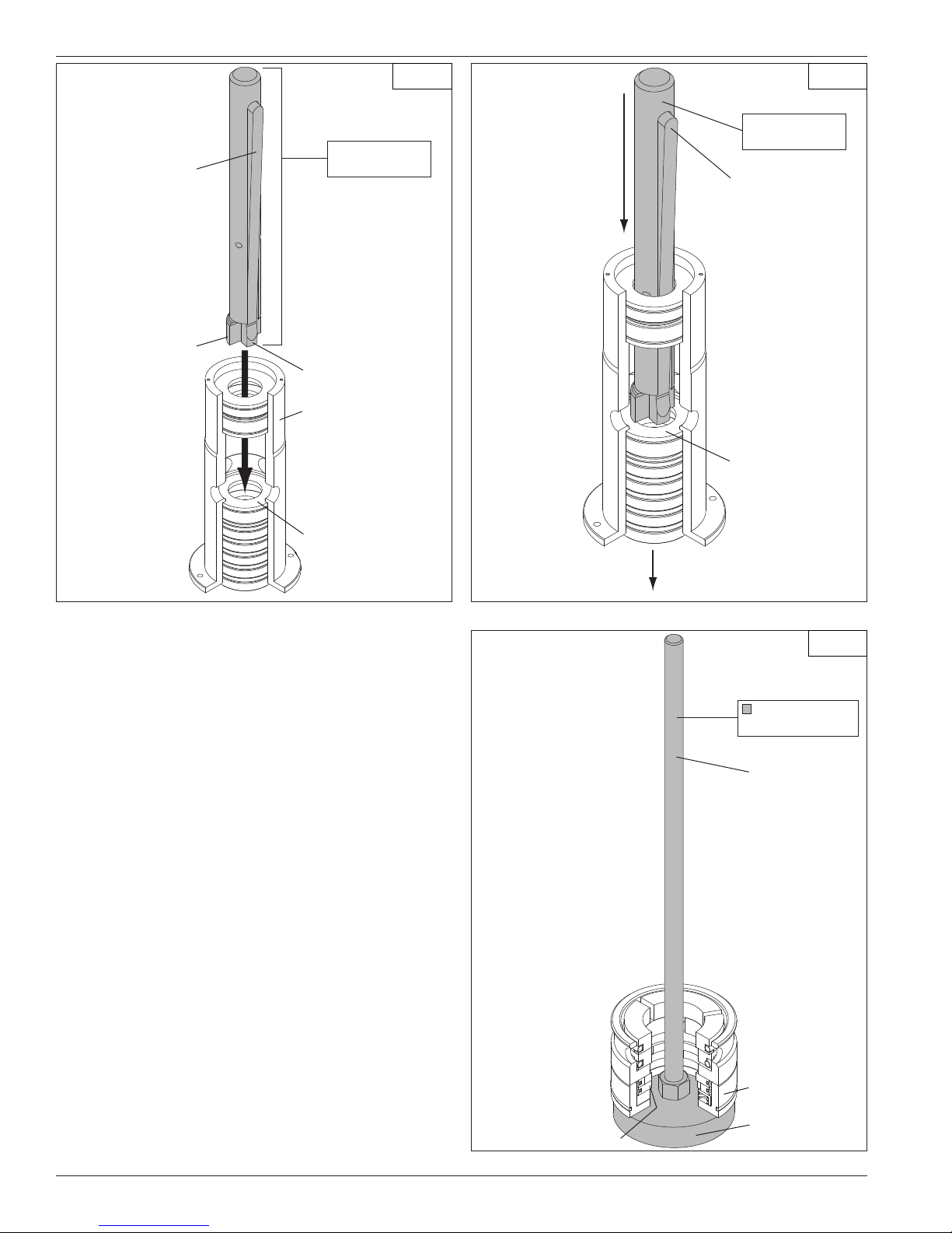
10. Inner Packing: Remove the purge packing cup,
segmented packing, oil wiper cup, oil wiper ring set, etc.
from the cylinder side of the packing cartridge adapter.
Assembly of Packing—T-style Compressor Models
THG601 and THG602
1. Always use new O-rings, packing sets and oil wiper
ring sets during assembly.
2. Clean the packing cartridge body and parts removed
from it during disassembly process.
3. Refer to Appendix D and note the order in which the
parts are to be installed and their correct orientation.
4. Inner Packing: The inner packing set is most easily
assembled using Packing Assembly Tool 4794-X.
a. Set the end plate of the Tool 4794-X on a
horizontal work surface and remove the slotted
clamp of the tool.
Step 1
Packing assembly
tool (4974-X)
Rod
b. Place a purge packing cup and a biased packing
set (TTs) onto the end plate of the tool and over
the rod of the tool. The cylinder side of the packing
should face the end plate of the tool such that the
springs in the biased packing set face toward the
end plate. NOTE: The 6 springs in the biased
packing sets are very small and fit loosely,
Biased packing set (TTs)
22
Purge packing cup
End plate
Figure 4.6C: Packing assembly
Nut
Rod
Step 2 Step 3
Packing assembly
tool (4974-X)
Slotted clamp
Packing cartridge adapter
Packing assembly
tool (4974-X)
Slotted clamp
Wiper ring cup and
inner oil wiper ring set
Purge packing cup and
inner packing set
End plate
Figure 4.6D : Packing assembly
Packing cartridge
body
Step 4
Inner packing set
End plate
Packing cartridge
adapter
Figure 4.6E : Packing assembly
so extra care is needed to keep from losing
them or having them become dislodged during
assembly. Place the oil wiper ring cup and oil
wiper ring set onto the purge packing cup. You
now have a full inner packing set positioned on the
end plate of the tool. See Figure 4.6C.
c. Orient the packing cartridge adapter so that the
open end (cylinder side) faces down. Being careful
not to dislodge the inner packing set previously
placed on the end plate of the tool, position the
packing cartridge adapter over the inner packing
set and end plate of the tool so that the rod of
the tool extends through the packing cartridge
adapter. Place the slotted clamp above the packing
cartridge adapter as shown in Figure 4.6D.
Inner
packing
set
Figure 4.6F : Packing assembly
Cup spacer
Socket head
screw
Packing cartridge
adapter
d. Tighten the nut on the rod of the tool until the
inner packing set is fully drawn into the packing
cartridge adapter. See Figure 4.6E.
e. Invert the packing cartridge adapter with the inner
packing set in it, and remove Tool 4794-X. Slide
the cup spacer into the packing cartridge adapter
so that it engages the inner packing set. See
Figure 4.6F.
f. Place an oil deflector ring inside the cup spacer
so that it is generally concentric with the inner
packing set.
23

5. Middle Packing
a. For compressors set up for pad packing
(Specification Code G), install a purge packing
cup with O-ring and a biased packing set (tangenttangent with springs toward cylinder [TTs]) into
the crankcase side of the packing cartridge body.
NOTE: The 6 springs in the biased packing sets
are very small and fit loosely, so extra care is
needed to keep from losing them or having them
become dislodged during assembly.
b. Install an O-ring on a packing spacer and install
both into the crankcase side of the packing
cartridge body.
c. Install a backup ring, segmented packing set (tangent-
tangent [TT]) and packing cup with O-ring into the
crankcase side of the packing cartridge body.
d. For compressors set up for purge packing
(Specification Code H), the middle packing set
components are installed in the opposite order
from Specification Code G, so that the springs
are toward the crankcase side of the packing
cartridge body.
e. For both Specification Codes G and H, install the
packing cartridge adapter onto the crankcase
side of the packing cartridge body such that the
cup spacer slides into the crankcase side of the
packing cartridge adapter and engages the middle
packing set to retain it in the packing cartridge
body. Attach the packing cartridge adapter to the
packing cartridge body with the four small socket
head screws.
f. Install a new O-ring on the outside of the packing
cartridge adapter and inside the adapter
g. Install a packing installation cone (Part no. 3905)
on the threaded end of the piston rod.
h. Carefully install the completed packing cartridge
assembly on the piston rod and insert into the
adapter. Be sure the mark previously made on the
packing cartridge body is oriented up because
most packing cartridge bodies can only be
installed in one position.
i. Install the packing cartridge cap in the adapter.
Be sure the mark previously made on the
packing cartridge cap is oriented up because
the packing cartridge cap can only be installed
in one position. On 2-3/4", 3-1/4" and 4"
Cylinders only, insure that the pin extending
from the outer end of the packing box cartridge
fits into the corresponding hole in the packing
cartridge cap.
j. Attach the packing cartridge cap to the adapter
with the four socket head bolts
k. Remove the packing installation cone.
7. Replace the cylinder, pistons and cylinder head (along
with adjustable head components, if any).
8. Rotate unit by hand to insure proper assembly.
4.7 Bearing Replacement for
Crankcase and Connecting Rod
6. Outer Packing
a. Install a purge packing cup with O-ring and biased
packing set (tangent-tangent with springs toward
crankcase [sTT]) into cylinder side of packing
cartridge body.
b. Install an O-ring on a packing spacer, and install
both into cylinder side of packing cartridge body.
c. Install a back-up ring, segmented packing set
(tangent-tangent [TT]) and packing cup with O-ring
into the cylinder side of packing cartridge body.
d. Install a back-up ring, segmented packing set
(radial-tangent [RT]) and packing cup with O-ring
into the cylinder side of packing cartridge body.
Repeat this process for remaining RT packing sets
e. Install a pressure breaker ring (not included on 6"
and 8" cylinders) and final packing cup with O-ring
into the cylinder side of packing cartridge body
1. To replace the crankcase roller bearings, wrist
pin bushing and connecting rod bearings, begin
by removing the head (or head, adjustable cap
and adjustable cup - applies to adjustable head
configuration only), cylinder, pistons, adapter, distance
piece (THG600 only) and crosshead and connecting
rod assemblies.
2. Drain the crankcase and remove the inspection plates.
3. Choose and mark one connecting rod and the
corresponding connecting rod cap to identify them. DO
NOT MIX CONNECTING RODS AND CAPS. Loosen
and remove the connecting rod nuts in order to remove
the crosshead and connecting rod assemblies.
4.7.1 Wrist Pin Bushing Replacement
1. To replace the wrist pin bushing, remove the retainer
rings that position the wrist pin in the crosshead.
2. Press out the wrist pin so the crosshead and
connecting rod may be separated. Inspect the wrist
pin for wear and damage and replace if necessary.
24
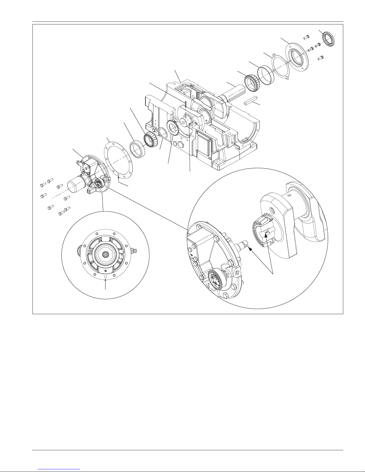
Crankcase
Oil seal
Bearing cover
Shim
Bearing cup
Bearing cone
Bearing carrier
Bearing cone
Bearing cup
Bearing carrier
gasket
Backside of
bearing carrier
Drive pin
Spacer
Drive sprocket
Link pin
Make sure this hole is aligned
with the oil-passage hole
on the bearing carrier.
Crankshaft
Flywheel key
Oil-passage hole
Figu re 4.7
3. Press out the old wrist pin bushing and press a
new bushing into the connecting rod. DO NOT
MACHINE THE O.D. OR I.D. OF THE BUSHING
BEFORE PRESSING INTO CONNECTING ROD.
4. Make sure the lubrication hole in the bushing
matches the oil passage in the connecting rod. If the
holes do not align, drill out the bushing through the
connecting rod lubricant passage with a long drill.
Bore the wrist pin bushing I.D. as indicated. See
Appendix D for details. Over boring the bushing can
lead to premature failure of the wrist pin bushing
and/or wrist pin.
5. Inspect the oil passage for debris and clean thoroughly
before proceeding.
Align slot with the pin located
inside the crankshaft.
6. Press the wrist pin back into the crosshead and wrist
pin bushing and reinstall retainer rings. NOTE: The fit
between the wrist pin and bushing is tighter than on
lubricated air compressors and combustion engines.
4.7.2 Replacing Connecting Rod Bearings
The semi-circular connecting rod bearings are easily
replaced by removing the connecting rods. Make sure
the indentations in the connecting rod bearing and
connecting rod line up when installing the new bearings.
MAKE SURE THE ARROW AND/OR ALIGNMENT NOTCH
ON CONNECTING ROD AND CAP ARE ALIGNED. BE
SURE THE PREVIOUSLY MARKED CONNECTING ROD
AND CAP ARE KEPT TOGETHER.
Before reinstalling the crosshead/connecting rod
assemblies, make sure the crankshaft throw and bearing
25
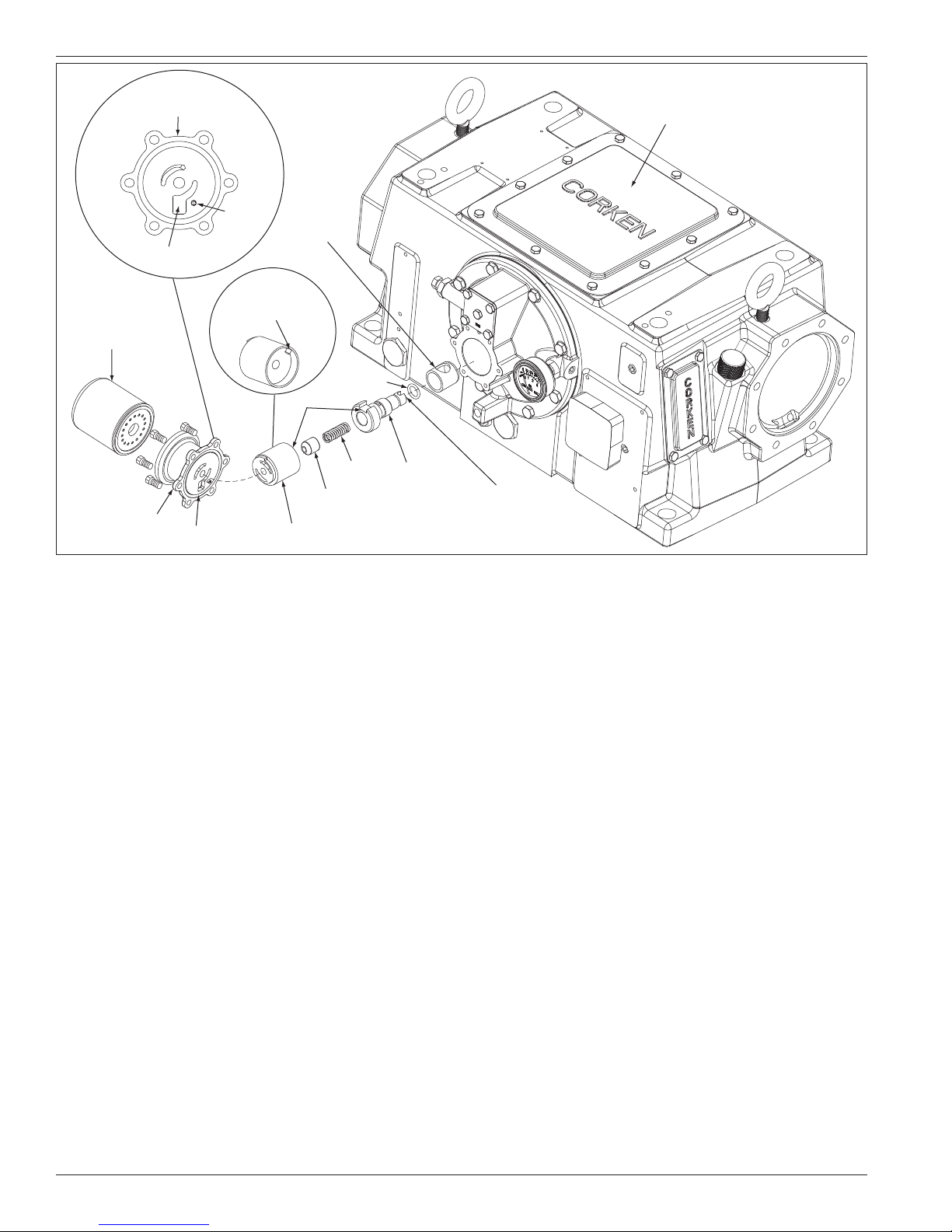
Backside of
oil filter adapter
Crankcase inspection plate:
Fill crankcase with oil through
this opening.
Oil suction
Oil filter
Oil filter adapter
Pin
Align pin with slot
on pump shaft
adapter.
O-ring
Pump shaft
bushing
Spring
Spring guide
Oil pump assembly
O-ring
Pump shaft
adapter
Figure 4.7: Oil Pump Inspection
surface are clean and lubricated. Tighten the connecting
rod nuts to the torque value listed in Appendix B.
4.7.3 Replacing Crankcase Roller Bearings
To inspect the roller bearings, you must remove the
flywheel, flywheel hub, bearing carrier and crankshaft
using the following steps.
1. Remove the flywheel from the crankshaft by removing
the three bolts that holds the flywheel to the hub. After
removal, re-insert the bolts into the three THREADED
flywheel removal holes (see figure 2.2A for details).
Tighten the bolts EVENLY to remove the flywheel from
the flywheel hub.
2. After the flywheel has been removed, remove the hub
from the crankshaft. If the hub will not slide off the
crankshaft easily, gently insert a flat head screw driver
into the split on the hub and lightly tap with a screw
driver. The hub should easily slide off the shaft.
3. Remove the bearing carrier and crankshaft from the
crankcase (see figure 4.7 for details). If corrosion
or pitting is present, the roller bearings should be
replaced. When replacing the roller bearings, always
replace the entire bearing and not just the cup or
the cone. Purchasing extra shims is recommended
as well. For crankcase assembly details, refer to
Appendix D and figure 4.6.
Align slot with
the pin at the end of
the crankshaft.
NOTE: REMOVING AND REPLACING THE BEARING
CONES AND BEARING CUPS (STEPS FOUR AND
FIVE LISTED BELOW) REQUIRES THE SERVICES
OF A PROFESSIONAL MACHINE SHOP. DO NOT
ATTEMPT TO REPLACE THEM IN THE FIELD.
4. To replace the bearings, press out the bearing cup
on the flywheel side of the crankcase and the other
bearing cup located on the bearing carrier. Using a
bearing puller, remove the bearing cones from each
end of the crankshaft.
5. Press one new bearing cup into the bearing
carrier and press the other new bearing cup
into the crankcase (opposite the bearing carrier
side). Press one bearing cone on each end of
the crankshaft. Insert the crankshaft through the
bearing carrier opening. The flywheel side of the
crankshaft should slide through the opening of the
bearing cup and bearing cover. Slowly lower the
opposite end of the crankshaft to the bottom of the
bearing carrier opening.
6. Before installing the bearing carrier, make sure
the slot at the end of the oil pump shaft is
aligned with the pin located at the end of the
crankshaft. Alignment should be either twelve and
six o’clock or nine and three o’clock. Make sure the
gasket for the bearing carrier is installed correctly.
An improperly installed gasket will block the oil
passage (see figure 4.6).
26

7. Push the end of the crankshaft toward the crankcase
and pull back; if a clicking noise or motion is
detected, the crankshaft has too much endplay. See
Appendix B.
8. To reduce endplay, remove the bearing cover located
on the flywheel side of the crankcase and remove a
thin shim. Recheck the endplay after replacing the
bearing cover.
9. When there is no detectable endplay, the shaft
must still be able to rotate. If the crankshaft sticks
or becomes abnormally warm, then the crankshaft
bearings are too tight. If the crankshaft is too tight, add
more shims but do not over shim. (Appendix B lists
the proper crankshaft endplay). When the crankshaft
can be rotated by hand with proper endplay, the rest
of the compressor may be reassembled.
NOTE: if the crankshaft roller bearings are too tight
or too loose, premature bearing failure will result.
10. Reinstall the flywheel and check the runout as shown
in Appendix B.
6. Insert the pump shaft adapter so it engages the drive pin.
7. Next, insert the spring, spring guide and oil pump
assembly. The pin on the oil pump must align with the
slot in the oil pump shaft adapter.
8. As you attach the oil filter adapter to the bearing
carrier, make certain the pin on the back of the oil
filter adapter aligns with the opening on the oil pump
assembly as shown in figure 4.7. When you are sure
the pin is properly aligned, install the oil filter adapter
bolts finger tight. If alignment is correct, the oil filter
adapter will mount flush to the bearing carrier. If it
does not, re-check the pin alignment.
9. Tighten the bolts in an alternating sequence. See
section 1.7 for directions on oil pressure adjustment.
10. Finally, rotate the crankshaft by hand to ensure
smooth operation. Then rotate it in opposite directions,
listening for a click, which indicates proper alignment
of the oil pump’s pins and slots.
Chapter 5—Extended Storage
4.8 Oil Pump Inspection
If the compressor operates for a prolonged period with
dirty or contaminated crankcase oil, damage to the oil
pump and bearings may result.
1. To check the oil pump, unbolt the oil filter adapter
and remove the oil pump, spring guide, spring and oil
pump shaft adapter as shown in figure 4.7.
2. Inspect the gears in the oil pump for corrosion or
pitting and replace if necessary.
3. Check the oil pump shaft bushing in the bearing
carrier. If the bushing is corroded, pitted or worn, the
oil pump shaft bushing should be replaced. Inspect
and replace other parts as necessary.
4. Before reassembling the oil pump mechanism, replace
the O-rings in the oil filter adapter and on the oil pump
shaft adapter (see figure 4.7).
5. Rotate the drive pin in the crankshaft to a vertical
position for easiest reassembly.
Procedures
Following a few simple procedures will greatly minimize
the risk of the unit becoming corroded and damaged.
Corken recommends the following precautions to protect
the compressor during storage:
1. Drain the crankcase oil and refill with rust inhibiting oil.
2. Operate for a few minutes while fogging oil into the
compressor suction.
3. Relieve V-belt tension.
4. Plug all openings to prevent entry of insects and
moisture. (The cylinders may also be protected by the
use of a vapor phase inhibitor, silica gel, or dry nitrogen
gas. If the silica gel is used, hang a tag on the unit
indicating that it must be removed before start-up.)
5. Store in a dry area and off the ground if possible.
6. Rotate the flywheel every two weeks if possible.
27
 Loading...