

Corken B166, T166 Installation, Operation & Maintenance Manual
ORIGINAL INSTRUCTIONS IH100G
Installation, Operation
& Maintenance Manual
Models B166 and T166 External Automatic
Bypass Valves
Model B166 External
Automatic Bypass Valve
Warning: (1) Periodic inspection and maintenance of Corken products is essential. (2) Inspection, maintenance and installation of Corken products
must be made only by experienced, trained and qualied personnel. (3) Maintenance, use and installation of Corken products must comply with
Corken instructions, applicable laws and safety standards (such as NFPA Pamphlet 58 for LP-Gas and ANSI K61.1-1972 for Anhydrous Ammonia).
(4) Transfer of toxic, dangerous, ammable or explosive substances using Corken products is at user’s risk and equipment should be operated
only by qualied personnel according to applicable laws and safety standards.
Model T166 External
Automatic Bypass Valve
Solutions beyond products...

Warning
Install, use and maintain this equipment according to Corken’s instructions and all applicable federal, state, local laws
and codes. Periodic inspection and maintenance is essential.
Corken One Year Warranty
CORKEN, INC. warrants that its products will be free from defects in material and workmanship for a period of one
year from date of installation, provided that the warranty shall not extend beyond twenty-four (24) months from the date
of shipment from CORKEN. If a warranty dispute occurs, the DISTRIBUTOR may be required to provide CORKEN
with proof of date of sale. The minimum requirement would be a copy of the DISTRIBUTOR’S invoice to the customer.
CORKEN products which fail within the warrant period due to defects in material or workmanship will be repaired or
replaced at CORKEN’s option, when returned, freight prepaid to CORKEN, INC., 3805 N.W. 36th St., Oklahoma City,
Ok l a h o m a 73112 .
Parts subject to wear or abuse, such as mechanical seals, blades, piston rings, valves and packing, and other parts
showing signs of abuse, neglect or failure to be properly maintained are not covered by this limited warranty. Also,
equipment, parts and accessories not manufactured by CORKEN but furnished with CORKEN products are not
covered by this limited warranty and the purchaser must look to the original manufacturer’s warranty, if any. This limited
warranty is void if the CORKEN product has been altered or repaired without the consent of CORKEN.
All implied warranties, including any implied warranty of merchantability or fitness for a particular purpose, are
expressly negated to the extent permitted by law and shall in no event extend beyond the expressed warrantee period.
CORKEN DISCLAIMS ANY LIABILITY FOR CONSEQUENTIAL DAMAGES DUE TO BREACH OF ANY WRITTEN OR
IMPLIED WARRANTY ON CORKEN PRODUCTS. Transfer of toxic, dangerous, flammable or explosive substances
using CORKEN products is at the user’s risk. Experienced, trained personnel in compliance with governmental and
industrial safety standards should handle such substances.
Important notes relating to the European Union (EU) Machinery Directive
Pumps delivered without electric motors are not considered as machines in the EU Machinery Directive. These pumps
will be delivered with a Declaration of Incorporation. The fabricator of the machinery must assure and declare full
compliance with this Directive before the machine in which the pump will be incorporated, or of which it is a part, is
put into service.
Contacting the Factory
Before you contact the factory, note the model number and serial number of your pump. The serial number directs
us to a file containing all information on material specifications and test data applying to your specific pump. When
ordering parts, the Corken service manual or Operations, Installation and Maintenance (IOM) manual should be
consulted for the proper part numbers. ALWAYS INCLUDE THE MODEL NUMBER AND SERIAL NUMBER WHEN
ORDERING PARTS.
The model and serial numbers are shown on the nameplate of the unit. Record this information for future reference.
Model No.
Serial No.
Date Purchased
Date Installed
Purchased From
Installed By
2

Table of Contents
APPLICABLE NOTICES FOR ATEX 2014/34/EU CONFORMITY ........................................4
FEATURES OF THE B166 EXTERNAL AUTOMATIC BYPASS VALVE ...................................5
CHAPTER 1—INSTALLATION OF THE B166 EXTERNAL AUTOMATIC BYPASS VALVE ...................5
1.1 Operation of the B166 External Automatic Bypass Valve ............................................5
FEATURES OF THE T166 AUTOMATIC EXTERNAL BYPASS VALVE ...................................7
CHAPTER 2—INSTALLATION OF THE T166 AUTOMATIC EXTERNAL BYPASS VALVE ...................7
2.1 Operation of the T166 Automatic External Bypass Valve ............................................7
APPENDICES
A. Model Number Identification Code and Available Options ...........................................9
B. Specifications ............................................................................10
C. Performance .............................................................................10
D. Outline Dimensions ........................................................................11
E. Parts Details .............................................................................13
3
Applicable Notices for ATEX
2014/34/EU Conformity
Product Type:
Corken Liquid Transfer Bypass Valves
Training Instructions:
Instructions for the safe application and use of this product
are provided in this manual. Read this manual completely
prior to installation and use of this product. Only qualified
and properly trained personnel should be allowed to install,
operate, and maintain this equipment.
Model Covered:
T16 6 O NLY
Intended Application:
The bypass valve models covered by this manual conform to
the European Union ATEX 2014/34/EU Directive for explosive
gas atmospheres and transfer of liquefied gases such as
Liquefied Petroleum Gas, anhydrous ammonia, freons, etc.
Possible Misuse Warning:
The designated bypass valve models must only be
installed in systems designed for its intended use, similar
to the examples presented in this manual.
ATEX Classification:
Group II; Category 2; G; Temperature Class T4 – T5
These products are classified under the ATEX directive
as Equipment – Group II – Category 2 – equipment is
intended for use in areas where explosive atmospheres
caused by gases or vapors (G) may be present. The
surface Temperature Class rating is a range between T4
275°F (135°C) and T5 212°F (100°C).
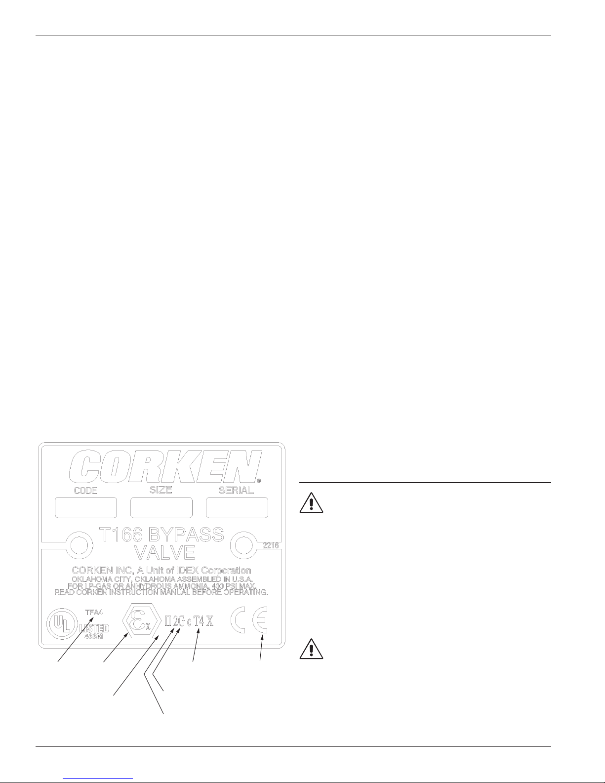
Nameplate:
Mechanical Ignition Sources:
The bypass valve is installed as part of an assembly including
the pump and the entire system must be grounded to prevent
possible electrostatic discharge. Installation and adjustment
guidelines are provided in this manual and are to be followed
for the proper operation and performance of the valve.
Sound Levels:
These products are reactionary devices used in pumping
systems. Sound levels are highly dependent upon the
application, product being pumped, and installation. When
operating in the system the valves should have a noise
level no higher than 80 dBA.
Piping Forces and Moments:
Maximum Allowable Nozzle Forces and Moments
Note: Piping systems should be designed according to
standard engineering practice and applicable national
and local codes. NO piping induced forces or moments
are recommended for Corken T166 bypass valves.
X—Horizontal (perpendicular to valve discharge port)
Y—Vertical
Z—Horizontal (parallel to valve discharge port)
Fx = Fy = Fz = 42 lb (19 kg)
Mx = My = Mz = 70 ft•lb (10 kg•m)
File number
Explosion
protection
ATEX Directive
2014/34/EU marking
Surface temperature
ran g e T4
(135°C) 275°F
Explosion gas
atmosphere high level
Equipment classified
as Group II—Catagory 2
ATE X an d
machinery
directive
Notice!
Corken bypass valves should only be installed in LPG
& NH3 systems that have been designed by qualified
engineering personnel and operated and maintained
by qualified technicians. The system must conform to
all applicable local and national regulations and safety
standards (specifically, LPG systems must conform to
NFPA 58). This manual must be kept with the bypass
valves and be reviewed before installing, operating or
performing any maintenance work.
Warning!
Do not attempt to open the pump or bypass valve until you
have bled off the pressure. High pressure in the system
can cause personal injury and/or property damage.
Please note: if the system contains a meter, the differential
valve will keep liquid under pressure in the pump, meter
and piping even after the hose has been emptied.
4
Features of the B166 External
Automatic Bypass Valve
The CORKEN B166 external bypass valve is a patented,
dual purpose, automatic priming and differential valve
designed for high-pressure volatile liquid service. This valve
may be used with stable liquids as well.
The B166 external bypass valve was also designed to work
in conjunction with CORKEN’s Coro-Flo® regenerative
turbine pumps but may be used with centrifugal pumps and
others as well.
To ensure optimum performance of the external bypass
valve and the entire pumping system, follow the instructions
in this manual.
Chapter 1—Installation of the B166
External Automatic Bypass Valve
Proper installation of the CORKEN B166 external bypass
valve ensures optimum performance of the pump and
external bypass valve. Install the B166 external bypass
valve on the discharge side of the pump in either a vertical
or horizontal position. All CORKEN Coro-Flo® turbine
pumps have a 3/4" NPT opening in the discharge nozzle for
piping this valve. When using other pump designs without a
3/4" NPT opening, a tee must be installed in the discharge
line. The discharge piping of the bypass valve should
connect to the vapor section of the supply tank using an
excess flow valve and not a back check valve. Do not
connect the outlet piping of the external bypass valve
to the inlet piping of the pump. A typical installation
is shown in Figure 1.1. The recommended pipe sizes for
discharge lines are given in the table below. For distances
of 50 feet or more, the next larger pipe size should be used.
Pipe Sizes for Discharge Line
Flow Rate
Up to 30 GPM 3/4" —
Up to 40 GPM — 1"
Pipe Size by Model Number
B166 B-.75 B166B -.1
1.1 Operation of the B166 External
Automatic Bypass Valve
Stationary Applications:
The differential pressure setting of the B166 external
bypass valve is adjustable. The range of differential
pressure depends on the size of the spring installed in
the bypass valve. When the bypass valve ships from
the CORKEN factory, a tag identifying the spring size
is attached to the valve bonnet. The table below shows
the part number and differential pressure range for each
spring. All of the springs are interchangeable with each
valve size.
Valve Model Spring Number
113 8 25–60
B166
119 3 50–150
119 3
1313
After the external bypass valve has been installed, it must
be set properly.
1. Install liquid-filled pressure gauges equipped with a
needle valve or snubber in the following locations:
a. Pump discharge gauge port or inlet side of the
bypass valve.
Differential Pressure
(PSIG)
100 –225
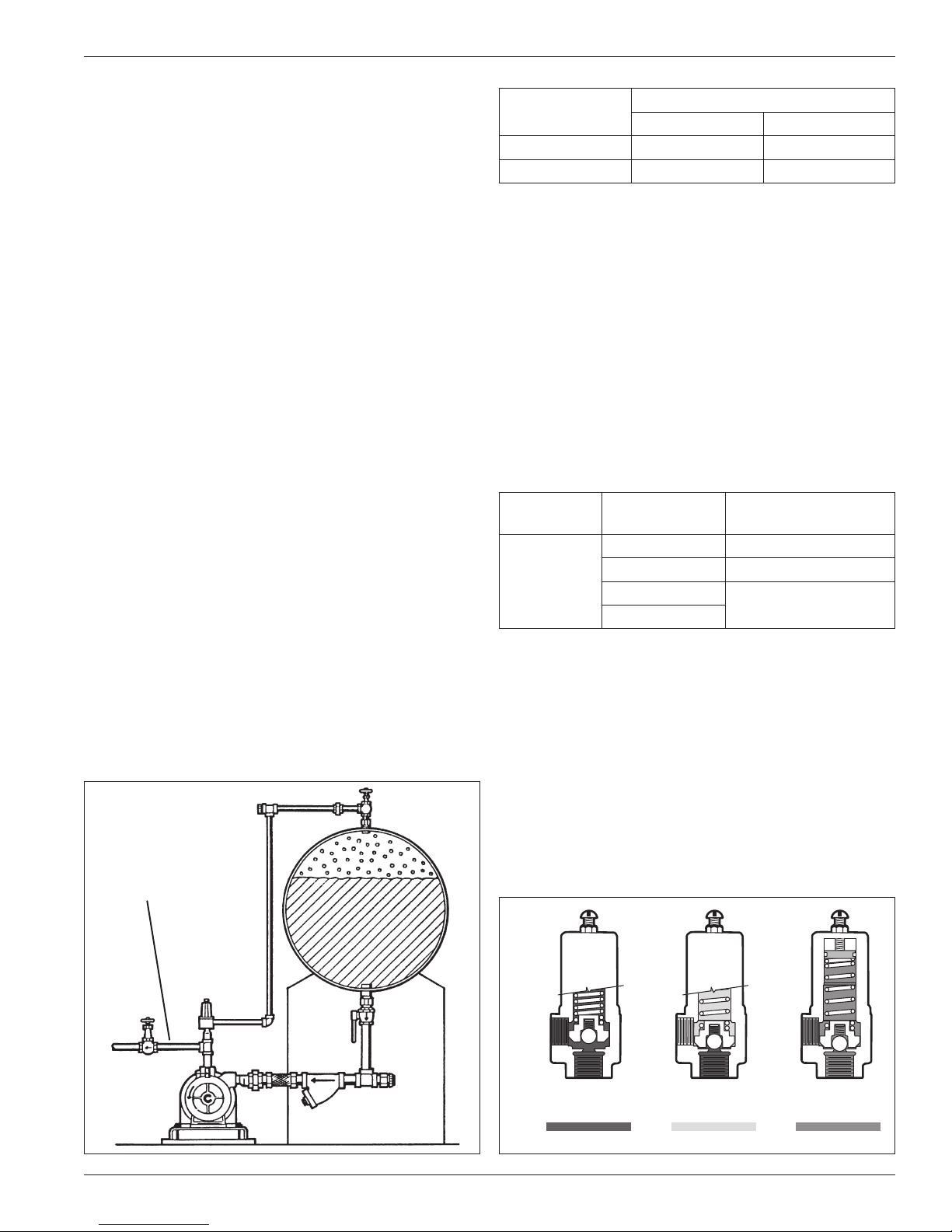
Discharge line
Figure 1.1: Typical installation. Figure 1.2: B166 with priming function.
b. Supply tank and/or pump suction.
2. Attach an ammeter to a motor lead of the electric motor.
Delivery line
shut-off or
pressure build
up is so high
that valve
opens and
relieves
capacity back
into supply
tank.
FIG. 1 Relieving Operation
No circulation
- all pump
capacity
going to
delivery.
INLET
OPEN
LIQUID VAPOR VAPOR and/or LIQUID
INLET INLET
FIG. 2 Pumping Operation
CLOSED
Liquid from
supply tank
seeking its
level in pump
and bypass
piping.
OUTLETOUTLETOUTLET
FIG. 3 Priming Operation
OPEN
5
 Loading...