

Corken 51, D51, 521, 1021, F1521 Installation, Operation & Maintenance Manual
...
ORIGINAL INSTRUCTIONS IC101H
Installation, Operation
& Maintenance Manual
Sliding-Vane Stationary Pumps for LPG and NH
All Models 51, 521, and 1021
D51 Mo de l
3
1021 Model
Warning: (1) Periodic inspection and maintenance of Corken products is essential. (2) Inspection, maintenance and installation of Corken
products must be made only by experienced, trained and qualified personnel. (3) Maintenance, use and installation of Corken products
must comply with Corken instructions, applicable laws and safety standards (such as NFPA Pamphlet 58 for LP-Gas and ANSI K61.1-1972
for Anhydrous Ammonia). (4) Transfer of toxic, dangerous, flammable or explosive substances using Corken products is at user’s risk and
equipment should be operated only by qualified personnel according to applicable laws and safety standards.
Solutions beyond products...

Warning
Install, use and maintain this equipment according to Corken’s instructions and all applicable federal, state, local laws
and codes. Periodic inspection and maintenance is essential.
Corken One Year Warranty
CORKEN, INC. warrants that its products will be free from defects in material and workmanship for a period of
one year from date of installation, provided that the warranty shall not extend beyond twenty-four (24) months from
the date of shipment from CORKEN. If a warranty dispute occurs, the DISTRIBUTOR may be required to provide
CORKEN with proof of date of sale. The minimum requirement would be a copy of the DISTRIBUTOR’S invoice to
the customer.
CORKEN products which fail within the warrant period due to defects in material or workmanship will be repaired or
replaced at CORKEN’s option, when returned, freight prepaid to CORKEN, INC., 3805 N.W. 36th St., Oklahoma City,
Oklahoma 73112.
Parts subject to wear or abuse, such as mechanical seals, blades, piston rings, valves and packing, and other parts
showing signs of abuse, neglect or failure to be properly maintained are not covered by this limited warranty. Also,
equipment, parts and accessories not manufactured by CORKEN but furnished with CORKEN products are not
covered by this limited warranty and the purchaser must look to the original manufacturer’s warranty, if any. This
limited warranty is void if the CORKEN product has been altered or repaired without the consent of CORKEN.
All implied warranties, including any implied warranty of merchantability or fitness for a particular purpose, are expressly
negated to the extent permitted by law and shall in no event extend beyond the expressed warrantee period.
CORKEN DISCLAIMS ANY LIABILITY FOR CONSEQUENTIAL DAMAGES DUE TO BREACH OF ANY WRITTEN OR
IMPLIED WARRANTY ON CORKEN PRODUCTS. Transfer of toxic, dangerous, flammable or explosive substances
using CORKEN products is at the user’s risk. Experienced, trained personnel in compliance with governmental and
industrial safety standards should handle such substances.
Important notes relating to the European Union (EU) Machinery Directive
Pumps delivered without electric motors are not considered as machines in the EU Machinery Directive. These
pumps will be delivered with a Declaration of Incorporation. The fabricator of the machinery must assure and declare
full compliance with this Directive before the machine in which the pump will be incorporated, or of which it is a part,
is put into service.
Contacting the Factory
Before you contact the factory, note the model number and serial number of your pump. The serial number directs
us to a file containing all information on material specifications and test data applying to your specific pump. When
ordering parts, the Corken service manual or Operations, Installation and Maintenance (IOM) manual should be
consulted for the proper part numbers. ALWAYS INCLUDE THE MODEL NUMBER AND SERIAL NUMBER WHEN
ORDERING PARTS.
The model and serial numbers are shown on the nameplate of the unit. Record this information for future reference.
Model No.
Serial No.
Date Purchased
Date Installed
Purchased From
Installed By
2

Table of Contents
Principles of a Sliding-Vane Pump ...............................................................4
Exclusive Features of the Coro-Vane® Pump ......................................................4
Chapter 1—Installation Procedures ..............................................................4
1.1 Location .................................................................................4
1.2 The Inlet Piping Should Include the Following: ...................................................6
1.3 The Outlet Piping Should Include the Following: ..................................................6
1.4 The Bypass System Must Include the Following: .................................................6
1.5 A Vapor Equalizing System Should be Included: ..................................................6
1.6 Driver Installation ..........................................................................6
Chapter 2—Operation Procedures ...............................................................7
Chapter 3—Maintenance Procedures ............................................................8
3.1 Preventative Maintenance Procedures .........................................................9
Chapter 4—Seal Replacement Instructions ......................................................10
4.1 Repair Kits and Spare Parts for Sliding-Vane Pumps .............................................13
Appendices
A. Model Number Identification Code and Available Options ..........................................14
B. Specifications ............................................................................16
C. Performance .............................................................................18
D. Outline Dimensions ........................................................................21
E. Parts Details .............................................................................28
F. V-Belt Selection ...........................................................................35
G. Troubleshooting Guide .....................................................................36
H. Extended Storage .........................................................................37
3

Principles of a Sliding-Vane Pump
Corken’s Coro-Vane® pumps are a special type of rotary
positive displacement pump, known as a sliding vane pump.
The PUMP NOZZLES on Models 521 and 1021 are
equipped with flanges to simplify piping. It is not
necessary to provide unions in the piping system near
the pump because the flanges serve this purpose.
The sliding-vane pump has many of the positive
displacement advantages of the gear pump, plus the
ability to compensate for wear, and operate at a lower
noise level.
The sliding-vane pump consists of a rotor turning in
a cam (liner) machined eccentrically in relation to the
rotor; thereby displacing the liquid trapped between
the rotor, cam and vanes. Coro-Vane® pumps are made
with vanes produced from advanced polymers which
exhibit extremely low coefficients of friction. The vanes
self-adjust for wear and extends the pump life.
Exclusive Features of the Coro-Vane® Pump
The pumping of volatile liquids is one of the most
difficult of all pumping jobs, so more attention must be
given to the design and manufacture of the pump and
to its installation and operation.
In addition to being especially suited for handling volatile
liquids, the Coro-Vane® pump has a number of features
to help make it more easily operated and maintained.
Coro-Vane® pumps are manufactured in six models:
the Models D51 and F51 small stationary and the
Models 521, 1021, F1021 and F1521 stationary pumps.
The Models F1021 and F1521 have ANSI flanged
connections. All six models have been registered and
listed by the UNDERWRITERS’ LABORATORIES, INC.
for use in the handling of LP-Gas and Ammonia.
The CASE AND HEADS are made of ductile iron for
extra strength and toughness.
The RELIEF VALVE is built-in as part of the pump on
models 521 and 1021 and is adjustable under pressure.
NOTE: EVEN WITH THIS INTERNAL SAFETY VALVE,
AN EXTERNAL BYPASS VALVE MUST BE INSTALLED.
Chapter 1—Installation Procedures
1.1 Location
The installation of the Coro-Vane® pump is simple;
however, in order for the pump to deliver optimum
performance, the principles discussed in this book
should be followed. The piping details in figure 1.2
illustrate methods proved by hundreds of installations.
Your own needs may require slight variations, but every
effort should be made to follow the recommendations
identified in this manual.
No pump can discharge more liquid than it receives, so
the pump location and the inlet piping must be given
careful attention. If the inlet piping is unable to supply
the demand of the pump, you may expect trouble. The
inlet sizes shown in figure 1.2 are the smallest piping
size you can use with success.
For the transfer of flammable liquids like LPG, the pump
must be installed according to the applicable local
safety and health regulations. The installer and/or the
user must take into account the following:
• The pump must be located as near the storage tank as
possible. The complete inlet line, including the vertical
line from the tank must not exceed twelve feet (3.7 m)
in length.
The VANES are manufactured of advanced polymers
to provide excellent life and quiet operation. After long
service, the vanes are simply and inexpensively replaced.
Both the CAM and the SIDEPLATES are easily replaced
should the need arise.
The MECHANICAL SEAL is designed for longer life
under greater loads and may be inspected or replaced
without disturbing the piping of the pump. No special
tools are needed.
BEARINGS are heavy-duty roller type for long bearing life.
PRESSURE GAUGE connections, 1/4" pipe thread,
are provided.
• The bottom of the tank must be no less than two feet
(0.6 m) above the pump inlet nozzle, with four feet
(1.2m) considered standard.
• The foundation for the pump is important. The foundation
must be firm, level and preferably made of concrete. The
suggestions in figure 1.1 should be observed.
1/2" x 8" anchor bolt
Pump base
Concrete
Fig u re 1.1
4
Metal shim
Large washer
• Potential risk due to local conditions regarding the
installation and operation (e.g. poor ventilation and
additional risks due to other elements in the vicinity, etc.).
should be used. Web slings are preferred over metal
slings to minimize damage to the paint. See Appendix D
for outline dimensions.
• Qualification of the personnel.
• Type of liquid being transferred.
• Specific safety measures to be applied (e.g. gas
detection, automatic shut-off valves, personal protective
equipment, etc.).
The following table shows the weight of the bare pump
for each model. For handling a bare pump, lifting slings
Model Shipping Weight: lb (kg)
D51 50 (22.7)
F51 25 (11.3)
521 132 (59.9)
1021 200 (90.7)
F1021 200 (90.7)
F1521 235 (10 6.6)
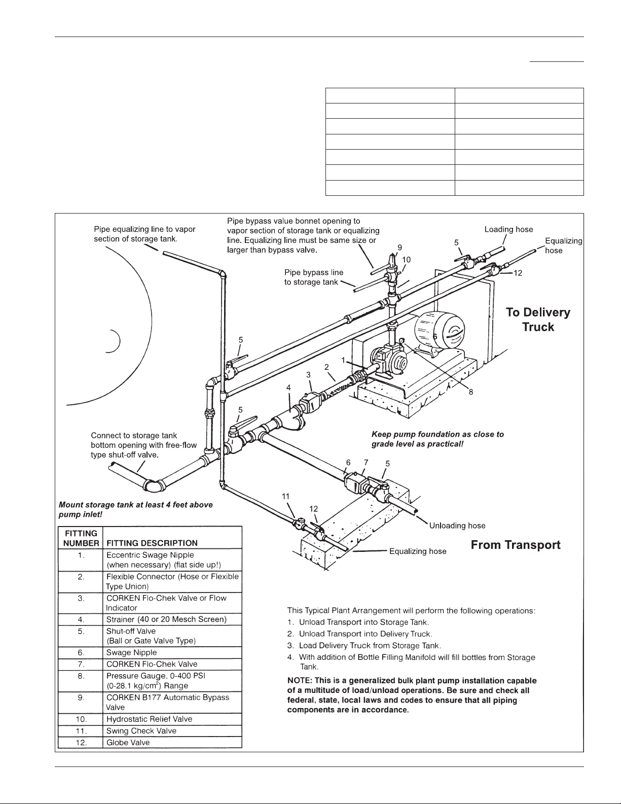
Figure 1.2: Typical Piping Diagram
5

1.2 The Inlet Piping Should Include the Following:
1. The tank excess flow valve (EFV) should have a flow
rate of 1-1/2 to 2 times the capacity of he pump. Do
not use an EFV without knowing its flow capacity.
Model Maximum Differential Pressure
521, 1021, F1021 125 psi (8.8 kg/cm2)
F1521 100 psi (7.0 kg/cm2)
1.5 A Vapor Equalizing System
2. The tank shut-off valve must be a free-flow type and
not a standard globe valve.
3. A strainer of the “Y” type, with 30 to 40 mesh screen,
must be on the inlet line of the pump. (Mesh size
indicates the number of openings per lineal inch).
4. Use a flexible connection in the pump inlet and outlet
piping to compensate for piping strains.
5. Use an eccentric swage at the pump inlet nozzle to
change the line size (flat side up).
6. Make the inlet line level or slope it downward to the pump.
7. The minium inlet piping sizes shown in figure 1.2 must
be observed.
1.3 The Outlet Piping Should
Include the Following:
1. A pressure gauge should be installed in the pump
outlet or near it. A pressure gauge is necessary to
determine the efficiency of your pumping system.
2. A hydrostatic relief valve is required by most state
laws and for your own safety.
3. If the outlet piping exceeds 50 feet (15.2 m) in length a
check valve should be installed near the pump outlet.
4. The minimum outlet piping sizes shown in figure 1.2
should be observed.
1.4 The Bypass System Must
Should be Included:
To obtain maximum performance from the Coro-Vane®
pump, a vapor equalizing system should be installed.
This system is simply a pipe connecting the vapor
sections of the tank being unloaded and the tank being
filled. This equalizing line allows vapor to move freely
between the two tanks (in either direction) and assures
that both tanks remain at the same pressure.
As liquid is withdrawn from a tank, it must be replaced
by an equal amount of vapor or the pressure in the tank
will drop. If an equalizing line is not present, this vapor
is formed by “boiling” of the liquid and a reduction of
the tank’s pressure. Meanwhile, the tank being filled
experiences a pressure increase as the rising fluid levels
compresses the vapor space above it. A vapor equalizing
line will eliminate both of these problems and will reduce
pumping time, differential pressure, noise and wear
on the entire system. Slow transfer rates will minimize
these effects and reduce the need for a vapor equalizing
line. However, today’s high transfer rates require the
installation of a vapor equalization line.
Another way to consider this principle is to remember
how it takes two holes in an oil can for oil to be poured
smoothly from the can; one for the oil to exit and the
other for the air to enter. The piping and hose sizes
shown in figure 1.2 are minimum requirements.
1.6 Driver Installation
Model Maximum Speed
521, 1021, F1021 950 RPM
F1521 860 RPM
Include the Following:
1. A pump bypass system must be installed. If the pump
discharge is shut off before the driver is stopped,
dangerously high pressures can develop, unless a
bypass valve is installed to permit the pump to discharge
back to the supply tank, at a predetermined pressure.
2. The pump may have an internal relief valve, but it is
intended as a safety relief valve device and not an
operational bypass.
3. Always install an external bypass relief valve (such
as the Corken B177) in the pump discharge line.
The bypass valve may discharge into the tank at any
convenient opening, either liquid or vapor; however, it
should not connect into the pump inlet piping system.
The wiring of your electric motor is extremely important
and must be done by a competent electrical contractor.
The following wire sizing chart indicates the minimum
standards for wire sizes.
6

Motor Recommended wire size, AWG
Hp Motor
3 1 115 34.0 6 4 2
5 1 115 56.0 4 1 1/0
7-1/2 1 230 40.0 8 6 4
10 3 230 28.0 8 8 8
15 3 230 42.0 6 6 6
20 3 230 54.0 4 4 4
25 3 230 68.0 2 2 2
30 3 230 80.0 1 1 1
40 3 230 100.0 2/0 2/0 2/0
50 3 230 130.0 3/0 3/0 3/0
1
Based upon 3% voltag e loss copper wire type TW. Single phase motor
calculations are based on two times distance.
Volts Approximate Full
Phase
3 230 9.6 12 12 12
3 230 15. 2 12 12 10
3 230 22.0 10 10 8
Load Amperes
220 17.0 12 8 8
460 4.8 12 12 12
230 28.0 10 6 4
460 7.6 12 12 12
450 11. 0 12 12 12
460 14.0 12 12 12
460 21.0 10 10 10
460 27.0 8 8 8
460 34.0 6 6 6
460 40.0 6 6 6
460 52.0 4 4 4
460 65.0 2 2 2
Length of Run (ft)
0–100 to 200 to 300
1
its power for every 1,000 feet (305 m) above sea level,
so if your installation is at a higher altitude than normal,
consult the factory.
Chapter 2—Operation Procedures
Performance curves and charts are provided in Appendix C.
The following steps should be performed for the initial
pumping operation:
1. Verify the strainer screen is clean.
2. Rotate the pump by hand.
3. Check V-belt drive or direct drive coupling alignment.
Misalignment will cause accelerated wear of the drive
system, motor bearings and pump.
4. Check motor for proper wiring.
5. Review complete system to make certain the function
of every valve and piece of equipment is clearly
understood. Everyone operating this system must be
properly trained in normal operating procedures and
emergency procedures in event of a malfunction.
6. Close all hose valves.
Improper motor wiring will cause expensive motor
difficulties from low voltage. If you suspect you have
low voltage, call your power company. Connecting your
motor for the voltage you have available is important
too. The motors furnished with the stationary pumps are
usually dual voltage, so you must be sure of the voltage
your power company is supplying you. Your motor will be
completely ruined if it is connected to the wrong voltage.
A humid climate can cause problems, particularly in
explosion proof motor applications. The normal breathing
of the motor, and alternating between being warm when
running and cool when stopped, often will cause moist
air to be drawn into the motor housing. This moist air will
condense, and may eventually add enough free water
to the inside of the motor to cause it to fail. To prevent
this, make a practice of running the motor and pump at
least once a week on a bright, dry day for an hour or so
(pumping through the bypass system). In this period the
motor will heat up and vaporize the condensed moisture,
and drive it out of the motor. No motor manufacturer will
guarantee an explosion proof or totally enclosed motor
against damage from moisture.
Engine drivers pose a special consideration. The
manufacturer’s instructions must be followed. When the
stationary pump is equipped with an engine from the
factory, the engine speed should normally not exceed
1,800 RPM. Excessive engine speed will overload the
engine and cause early failure. The engine loses 3% of
7. Slowly open the storage tank bottom shut-off valve
(suction line to the pump). Immediately check the
system for leaks.
8. Open any shut-off valves between the bypass valve
and the storage tank.
9. Make a note of all pressure gauge readings, especially
the pressure gauge located at the discharge of the
pump. Start the pump and circulate the liquid through
the bypass system back to the storage tank.
10. Verify the proper pump rotation direction. There is an
arrow cast in the pump case.
11. An ammeter may be used by adjusting the bypass
valve until the ammeter indicates the full load motor
amperage rating shown on the motor nameplate or
maximum rated differential, whichever comes first.
Permit the pump to circulate liquid for half an hour or
more. If the motor overload protection device stops
the motor in this period the bypass valve setting is
too high and should be readjusted until the motor
will run for half an hour. After a satisfactory setting is
achieved, “seal” the valve adjusting stem to prevent
tampering with the adjustment. See IH102 for more
details on the use of the Corken bypass valves.
12. If your pump has an internal relief valve, it must be
set higher than the external bypass setting. The
internal relief valve may be adjusted while the pump
7
is under pressure by removing the flush seal plug.
Turning the adjusting screw clockwise will decreases
the internal relief valve setting. Replace the flush seal
plug after adjustment.
13. After initial operation, re-check the strainer screen.
Chapter 3—Maintenance Procedures
ALL REPAIRS TO THE PUMP MUST BE
PERFORMED BY QUALIFIED PERSONNEL IN A
SAFE MANNER, UTILIZING TOOLS AND/OR
EQUIPMENT THAT ARE FREE OF HAZARDS, AND
FOLLOWS THE APPLICABLE SAFETY CODES OF
PRACTICE SET BY THE LOCAL AUTHORITIES HAVING
JURISDICTION. MAKE SURE THE SYSTEM PRESSURE
HAS BEEN RELIEVED BEFORE ATTEMPTING ANY
REPAIR TO THE PUMP.
A pump requires regular maintenance and care like
all mechanical equipment. A neglected or improperly
repaired pump will result in premature failure and cause
unsafe conditions.
To promote product longevity and safety, maintenance
must be performed by properly trained technicians. Make
sure all safety systems are in place and the system pressure
has been relieved before attempting ANY maintenance.
Make sure the transfer hoses are not “kinked” which can
cause excessive pump discharge pressure. Always make
sure your hoses are not out of date.
There are two lubrication points in which to grease
the pump bearings; one zerk per bearing cap located
at opposite ends of the pump. Four grease relief and
seal ventilation fittings have been provided, two at
each end of the pump, to prevent overgreasing the
bearings. Overgreasing can cause seal failure if grease
passageways are blocked in some way. Clean each
fitting before lubricating the bearings. This practice helps
to prevent foreign-material contamination of the bearings
and accidental over-pressurization of the mechanical
seals. Use only ball bearing grease (MIL-G-10924C) with
a temperature rating of -50°F.
Normal wear par ts are the mechanical shaft seals, bearings,
vanes and sideplates. All of these parts plus O-rings and
grease seals are offered in the Corken “repair kit” listed in
this manual directly after the Seal Replacement Instruction
on page 10. Use only genuine Corken replacement parts
when repairing the pump.
When it becomes necessary to repair your pump or
remove it from the system, you must be absolutely
certain that all propane, anhydrous ammonia or whatever
product being pumped is bled from the pump and
connecting piping. Once all the product has safely been
bled from the pump and connecting piping, make certain
no pressure is left in the system.
SPECIAL CARE MUST BE TAKEN DURING THE
BLEED DOWN PROCESS TO AVOID DANGER
TO PERSONNEL AND PROPERTY IN THE AREA.
Bleeding a system too fast is a common mistake and
may leave “refrigerated” liquid in the pump and piping
even though the pressure gauge shows no pressure.
As the “refrigerated” liquid begins to warm, more
gas will escape causing a dangerous condition. Take
your time in bleeding your system and make proper
provisions to vent or capture the gas in accordance
with local regulations. ONLY A PROPERLY TRAINED
INDIVIDUAL SHOULD BE ALLOWED TO BLEED A
PUMPING SYSTEM.
Pump Maintenance Schedule
Daily Monthly
Lubricate bearings X
Inspect drive coupling X
Clean inlet strainer X
Check for leaks X
Inspect hose and fittings X
1
Continuous duty applications may require monthly lubrication.
Figure 3
If the pump’s use is seasonal, then special care must be
taken during the off season to protect your pump from
corrosion. If it is feasible and safe to keep the pump
pressurized with product during the off season, this will
prevent the entrance of any moisture or air. This system
should be checked periodically to make certain all of the
gas has not bled out.
If the pump is to be removed from service for some time,
the pump must be protected., as propane, butane and
anhydrous ammonia all leave the metal “bare” and open to
corrosion. Piping and tanks not in service should also be
protected, as the rust that forms can destroy the pump’s
seals almost immediately after start-up. To prevent these
problems, complete the following:
1. Fill or thoroughly flush the pump with a light rust
inhibiting oil. If the pump is flushed with oil, placing
some desiccant packets inside the pump will provide
added protection.
2. Plug all pump openings.
3. Store in a dry location.
4. Before placing the pump back into service, drain the
oil and remove any desiccant packets.
5. Before operating the pump, refer to chapter 2 of this
manual for operation procedures.
Three
Months
1
8

3.1 Preventative Maintenance Procedures
Purpose
By following an effective preventive maintenance
program, unscheduled downtime can be eliminated. This
program should be used by the Operation Manager to
get a maximum utilization of manpower and equipment
as well as to prevent possible unsafe situations and/or
production delays due to equipment breakdown.
5. Lubricate Motor Bearing:
Follow the recommendations of the electric motor
manufacturer for the type of grease to use and the
lubrication frequency.
6. Performance Test:
a. While transferring liquid with the pump, check the
pressure at the pump’s inlet port. The pressure
drop in the inlet piping should not be greater than
3 psi.
Scope
The maintenance chart in figure 3 includes the items to be
regularly checked and inspected with a recommended time
schedule. These are basic maintenance recommendations,
and each company should develop their own comprehensive
preventive maintenance program schedule, tailor-made to
their individual operational procedures and requirements.
Maintenance must only be performed by a properly
trained and qualified individual following all the applicable
safety procedures.
Procedures
Every procedure herein recommended must be performed
in a safe manner (utilizing tools and/or equipment which
are free of hazards) and following the safety codes of
practice set by the authorities having jurisdiction. These
are general guidelines and are not intended to cover all
the safety aspects that must be considered and followed
while performing these procedures.
1. Visual Inspection:
This includes checking for leaks, corroded areas,
condition of hoses, piping and fittings, and any
unsafe condition which may hinder the safety of the
personnel and/or the facility.
b. While transferring liquid with the pump, close the
discharge valve(s) so the full flow will be directed
back to the storage tank through the bypass
valve. Then slowly close the valve downstream of
the bypass valves. The discharge pressure of the
pump should increase to the maximum differential
pressure of the pump at no flow conditions (see
Appendix C—Performance Curves).
c. If the maximum differential pressure is not obtained,
the pump must be serviced. See Appendix G—
Troubleshooting Guide for additional help.
d. Replace vanes or sideplates if worn.
7. Tighten all hold-down bolts.
8. Inspect motor starter contact points. This procedure
must be performed by an authorized and qualified
electrician according to the electric motor
manufacturer’s guidelines.
2. Clean Inlet Strainer Screen:
A clogged strainer screen will create too much flow
restriction and vapor will be formed causing the pump
to cavitate. This reduces the pump’s capacity and
accelerates the wear of the internal parts.
3. Inspect Drive Coupling and Driveline:
Check the coupling alignment and the condition of the
union for cuts, broken sections and wear.
4. Lubricate Pump Bearings:
Use only ball bearing grease, applied with a manual
lubrication pump or gun. Always clean the grease
openings thoroughly before greasing.
9
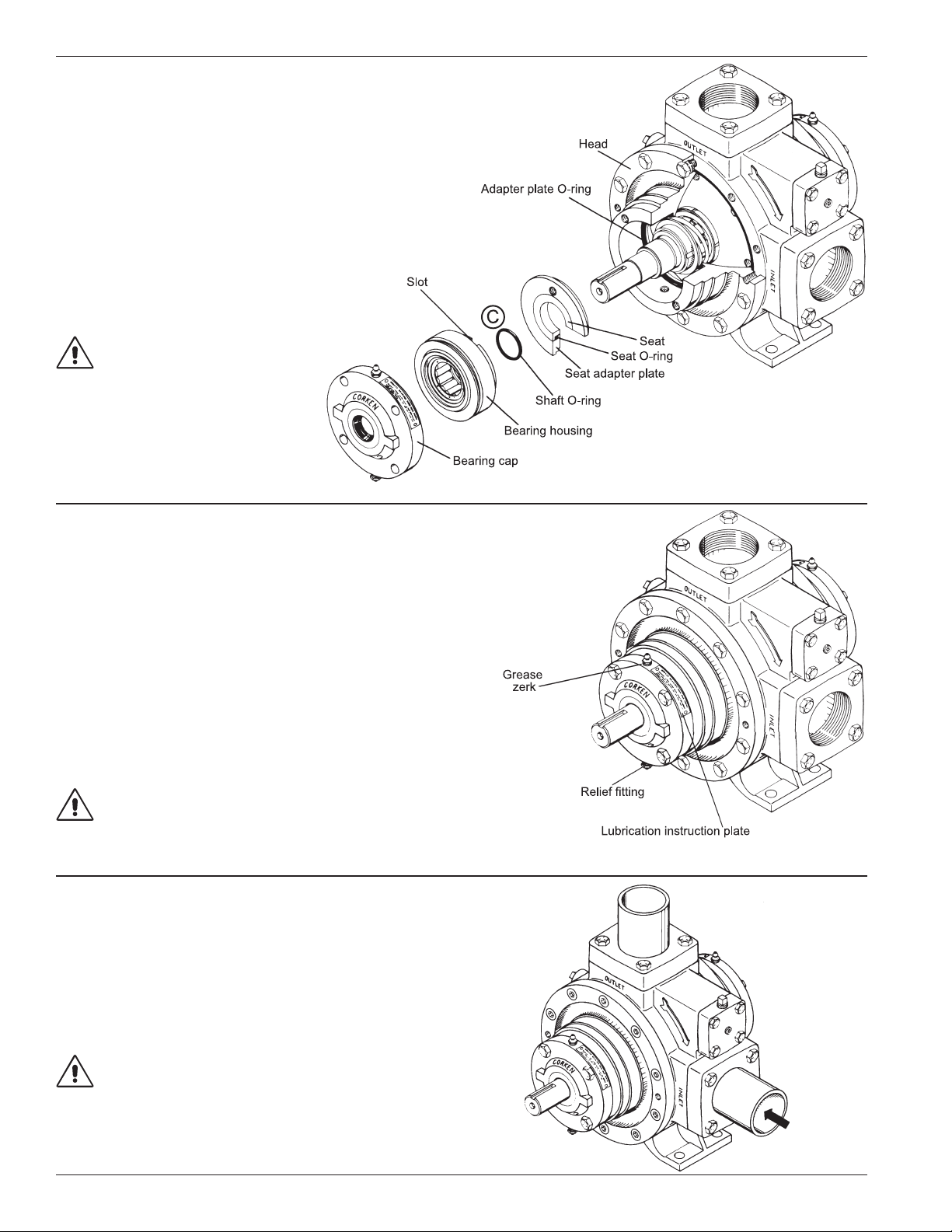
Chapter 4—Seal Replacement Instructions
For all models 521 and 1021.
Simple as A, B, C... but watch alignments A, B and C or
your new seal will leak!
Caution: Bleed all pressure from the pump and
piping before starting to install your seal assembly.
Cleanliness
Even the smallest amount of dirt on your new seal
can cause early failure. Keep all parts, tools and your
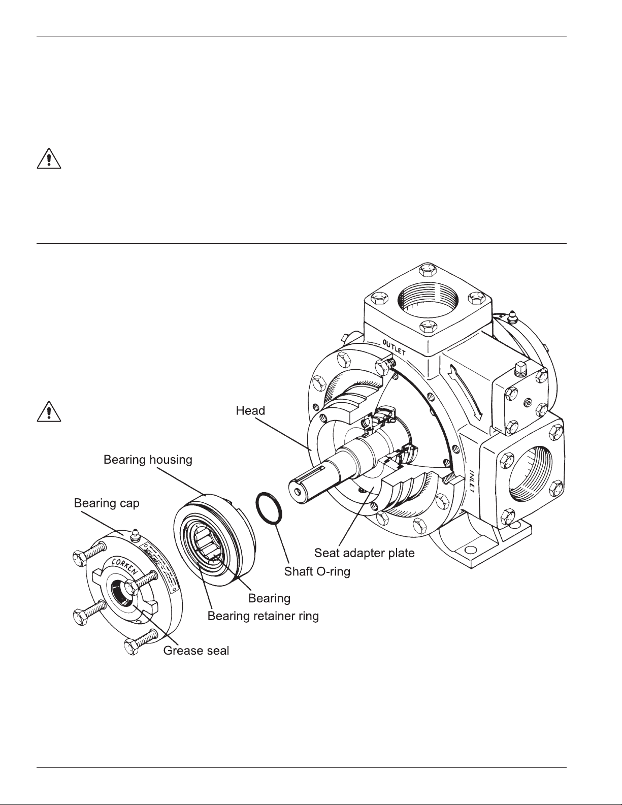
Step 1
Depressurize and open the pump.
Remove the bearing cap and bearing housing. Should
the bearing housing be rusted or frozen in place it may be
necessary to remove the entire pump head. The housing
can then be driven out gently with a block of wood.
hands clean while installing the seal. Never touch the
smooth lapped faces of the carbon rotor or seal seat.
With LP-Gas, anhydrous ammonia, and similar liquids,
the fluid is 5 to 10 times thinner than water so the
smooth/lapped surfaces of the new seal need to be as
clean as possible.
Workmanship
This pump is a precision piece of equipment with very
close clearances and should be treated with care. Never
beat on it when inserting or removing parts.
Remove the old shaft O-ring and discard it. Never reuse
an old O-ring except in an emergency. If you are also
installing a new bearing or grease seal do so now.
Follow established safety
regulations!
10
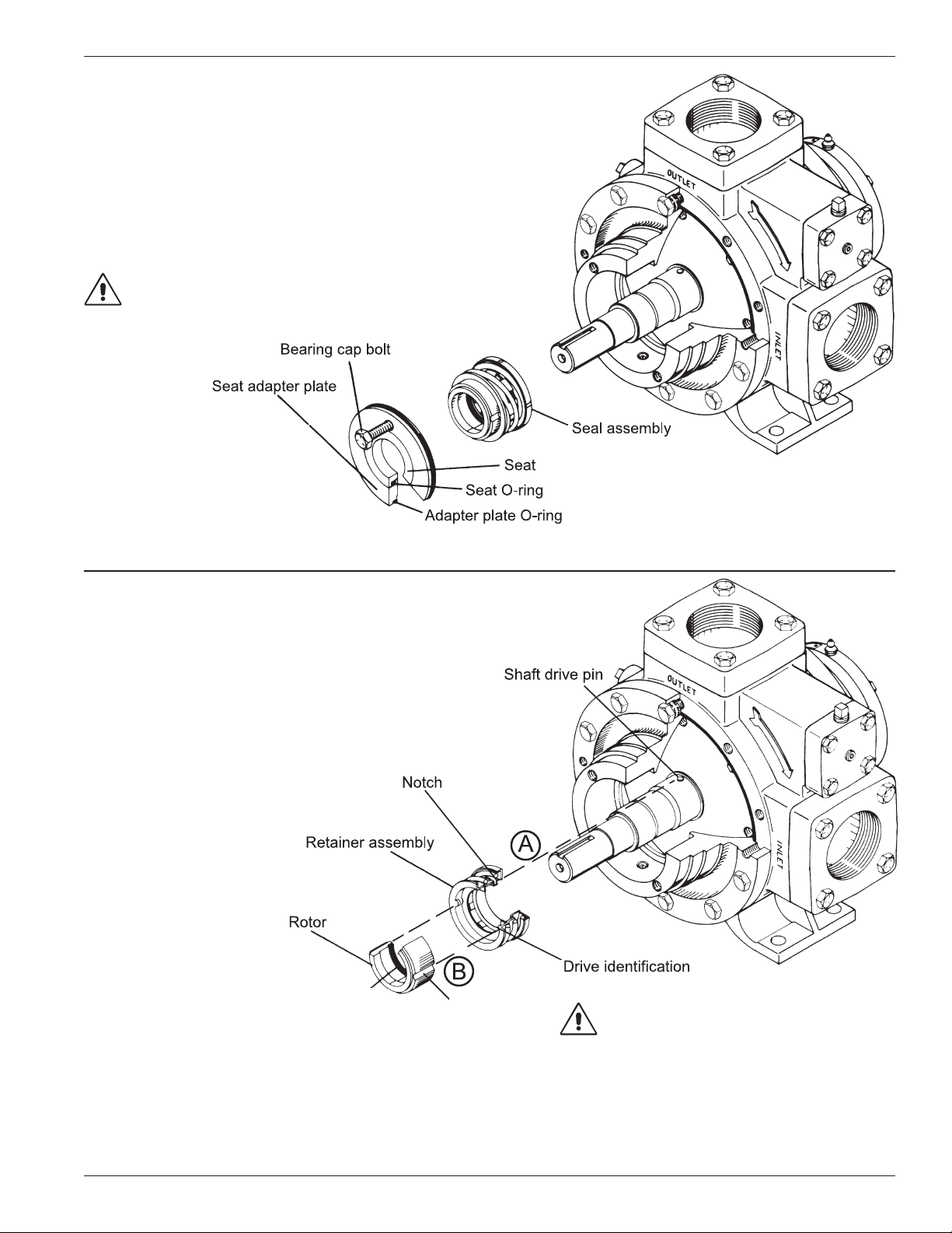
Step 2
Remove the old seal.
The seat adapter plate can be removed using a bearing
cap bolt as a puller. Disregard the old adapter plate O-ring,
seat, and seat O-ring. Remove and discard the rest of the
old seal. Thoroughly clean all surfaces that contact O-rings.
Use fine emery or crocus cloth. The shaft under the seal
O-ring should be shiny smooth. Lubricate all surfaces with
a clean, light oil. Do not let dirt settle on the parts.
Caution: Mechanical seals are precision devices.
Care must be used when handling and installing
the seal seat to prevent chipping or cracking.
Step 3
Proper alignment of the new seal.
This is the most critical step of the seal installation. With clean
hands unwrap the new seal without touching the seal faces.
A. Locate the notch on the back of the retainer assembly
and position over the shaft drive pin as shown in the
illustration. If the shaft drive pin is not aligned with the
notch, the seal will be
improperly positioned
and leak. It should not
require any force to install
the retainer assembly.
Hold the carbon rotor
without touching the
lapped face; lubricate
the rotor O-ring with a
light oil and install both
on the pump shaft. (For
the optional PTFE CoroSeal installation, see the
following paragraph.)
Rotor O-ring
(or optional Coro-Seal)
Groove
Watch alignments A and B!
If you are using the optional PTFE Coro-Seal, make sure
the shaft is very clean and smooth as the PTFE seal is not
as tolerant of surface blemishes as rubber O-rings. After
lubricating the Coro-Seal, install in the backside of carbon
rotor with the spring toward you and slide the carbon rotor
in position as previously described.
B. The two grooves in the carbon rotor must line up with
the drive indentations in the retainer assembly. If they
do not, the seal will be improperly positioned and
leak. Do not allow the carbon rotor to cock. This may
chip the lapped face.
11
Step 4
Completing the installation.
After applying some oil to the new adapter plate O-ring,
insert it into the pump head. Without touching the lapped
face, insert the new seat and oiled seat O-ring into the
adapter plate. Install the adapter plate in the pump head.
Install the shaft O-ring on the shaft.
C. Slide the bearing housing over the
shaft and install the bearing cap
using a criss-cross method on the
bolts and make sure the pump
shaft turns freely.
Watch alignment C!
Step 5
Proper lubrication.
For proper lubrication, use MIL-G-10924C ball bearing
grease only. Each pump is equipped with a grease zerk and
relief fitting. Before greasing the bearing, the grease zerk and
relief fitting must be cleaned thoroughly. If any dirt is forced
through the grease zerk, early bearing failure will result.
Overgreasing will damage the pump bearings. To help
prevent overgreasing, use a hand operated grease gun.
Insert the grease slowly and stop as soon as the relief
fitting opens. Excessive grease may drip out of the relief
fitting for several hours after lubrication.
Do not overgrease!
NOTE: When lubricating truck pumps, grease the U-joints
and the spline of the drive shaft as well.
Step 6
Repressurize the system.
For best results slowly pressurize the pump with vapor
before introducing liquid to the pump. When liquid enters
a unpressurized pump-even slowly-it can sometimes
refrigerate enough to keep the O-rings/elastomers from
sealing properly and cause a leak.
Vapor first, then liquid!
12
 Loading...