

Page 1
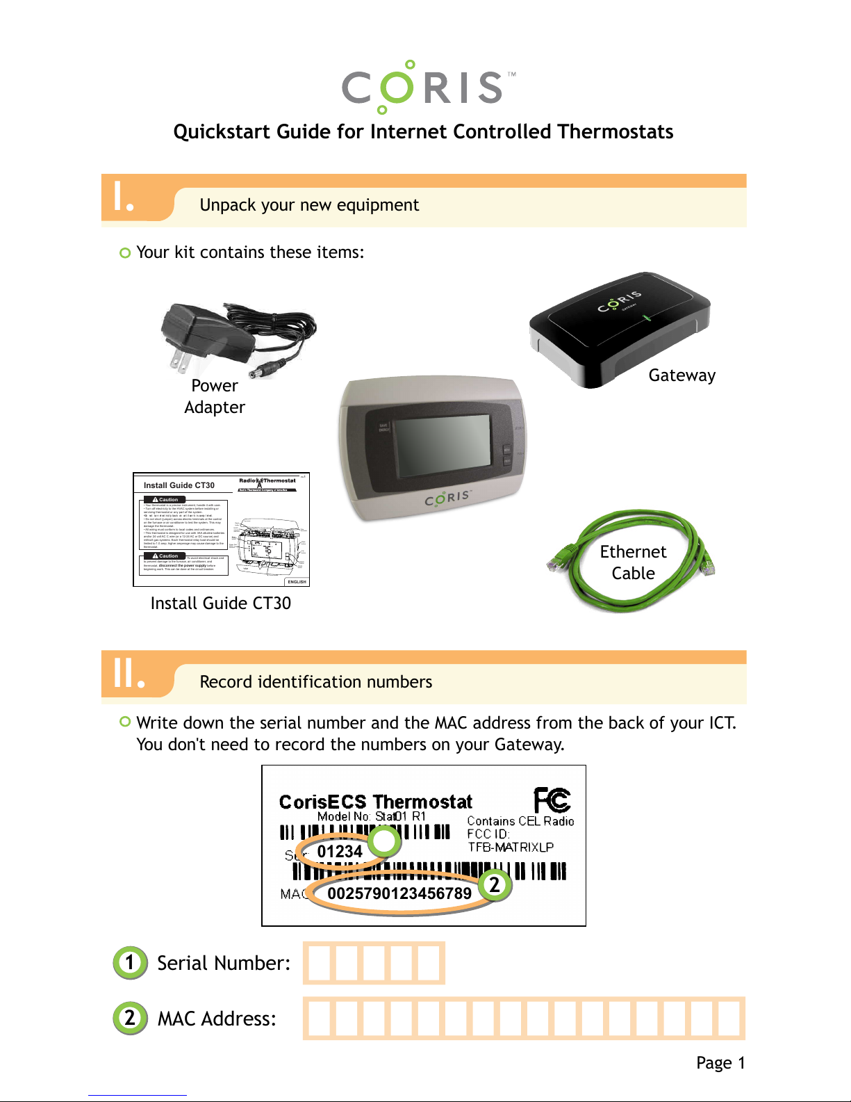
Your kit contains these items:
Quickstart Guide for Internet Controlled Thermostats
Serial Number:
MAC Address:
Gateway
Ethernet
Cable
Write down the serial number and the MAC address from the back of your ICT.
You don't need to record the numbers on your Gateway.
Power
Adapter
Page 1
I.
Unpack your new equipment
II.
Record identification numbers
2
1
$Id: page1.svg 4779 2012-02-28 20:32:45Z martini $
Install Guide CT30
PG1
Install Guide CT30
Caution
•Your thermostatis aprecise instrument, handleit withcare.
•Turn offelectricity tothe HVACsystem before installingor
servicingthermostat or anypart ofthe system.
•Do not turnelectricity backon until wor ki scomp l et ed.
•Do not short(jumper) acrosselectric terminalsat thecontrol
onthe furnace orair conditionerto testthe system.This may
damagethe thermostat.
•All wiringmust conform tolocal codesand ordinances.
•This thermostatis designed foruse with3AA alkalinebatteries
and/or24 voltAC C wire(or a12-24 ACor DCsource) and
millivoltgas systems. Eachthermostat relayload shouldbe
limitedto 1.0 amp;higher amperagemay causedamage tothe
thermostat.
Caution
Toavoid electricalshock and
toprevent damage tothe furnace,air conditioner,and
thermostat,disconnect thepower supplybefore
beginningwork. Thiscan be doneat thecircuit breaker.
ENGLISH
Save
Energy
button
PowerGrid
status
indicator
topcover
Touchscreen
Wire
terminals
Mode
button
Fan
button
MENU
butto
n
PROG
butto
Reset
button
HVAC
selections
switches
bottom
cover
DAY
F
LINK
RADIO
TARGETTEMP
1
COOL
A
U
TO
P
M
n
01234
0025790123456789
2
1
Internet Controlled
Thermostat (ICT)
Page 2
Have a licensed contractor or HVAC professional install your new ICT, using
the Install Guide CT-30 as a step-by-step reference.
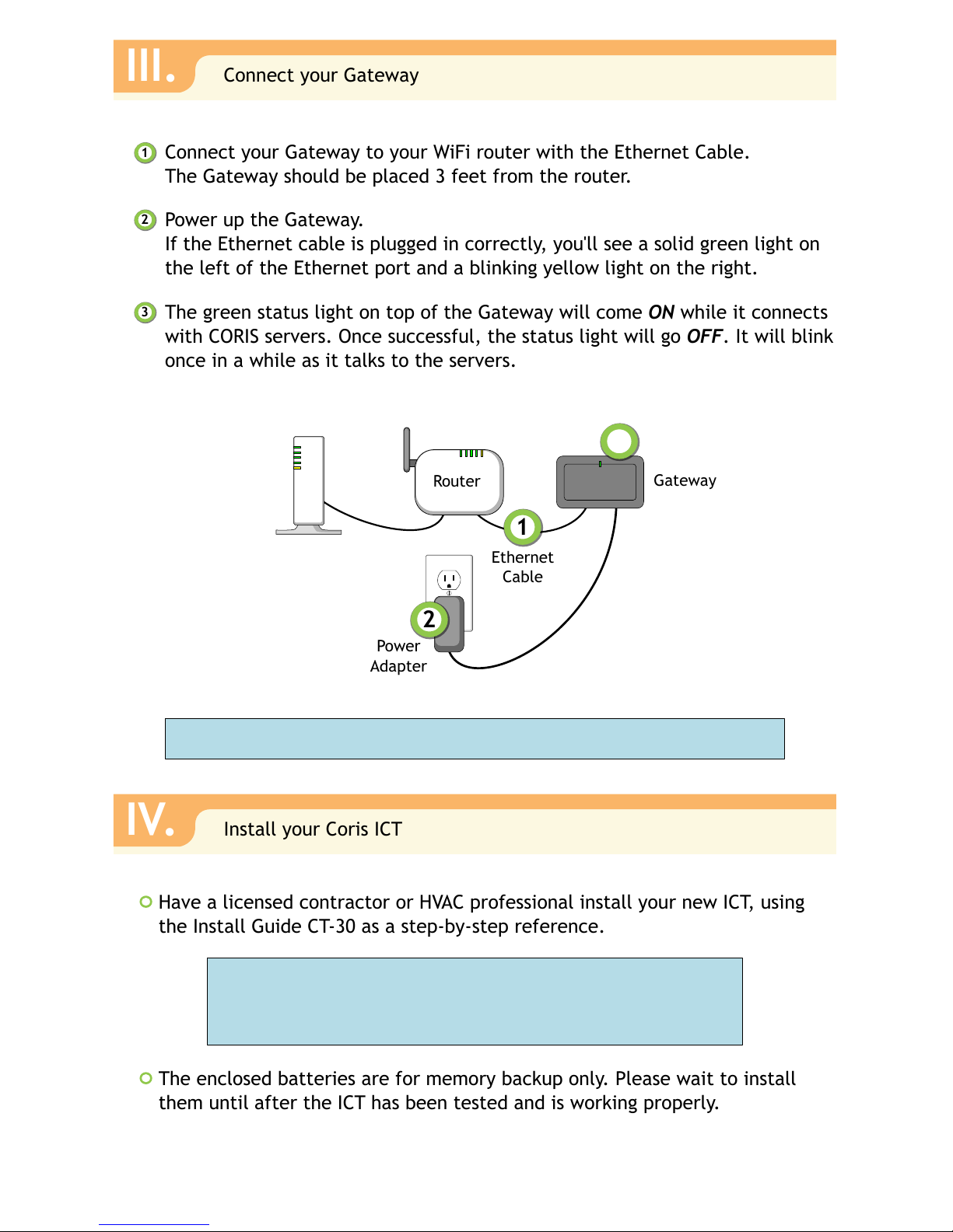
Connect your Gateway to your WiFi router with the Ethernet Cable.
The Gateway should be placed 3 feet from the router.
III.
Connect your Gateway
IV.
Install your Coris ICT
Power up the Gateway.
If the Ethernet cable is plugged in correctly, you'll see a solid green light on
the left of the Ethernet port and a blinking yellow light on the right.
The green status light on top of the Gateway will come ON while it connects
with CORIS servers. Once successful, the status light will go OFF. It will blink
once in a while as it talks to the servers.
2
1
3
The enclosed batteries are for memory backup only. Please wait to install
them until after the ICT has been tested and is working properly.
Power
Adapter
Ethernet
Cable
Router
1
2
Gateway
3
Cable
Modem
Note: Some wireless systems use all-in-one cable modems & routers.
Important: the ICT is a sophisticated electrical device;
please use an expert. If you need further assistance with
installation, please call the manufacturer at 877-602-5028.
Page 2
$Id: page2.svg 4845 2012-03-06 23:03:46Z martini $
Page 3
$Id: page3.svg 4845 2012-03-06 23:03:46Z martini $
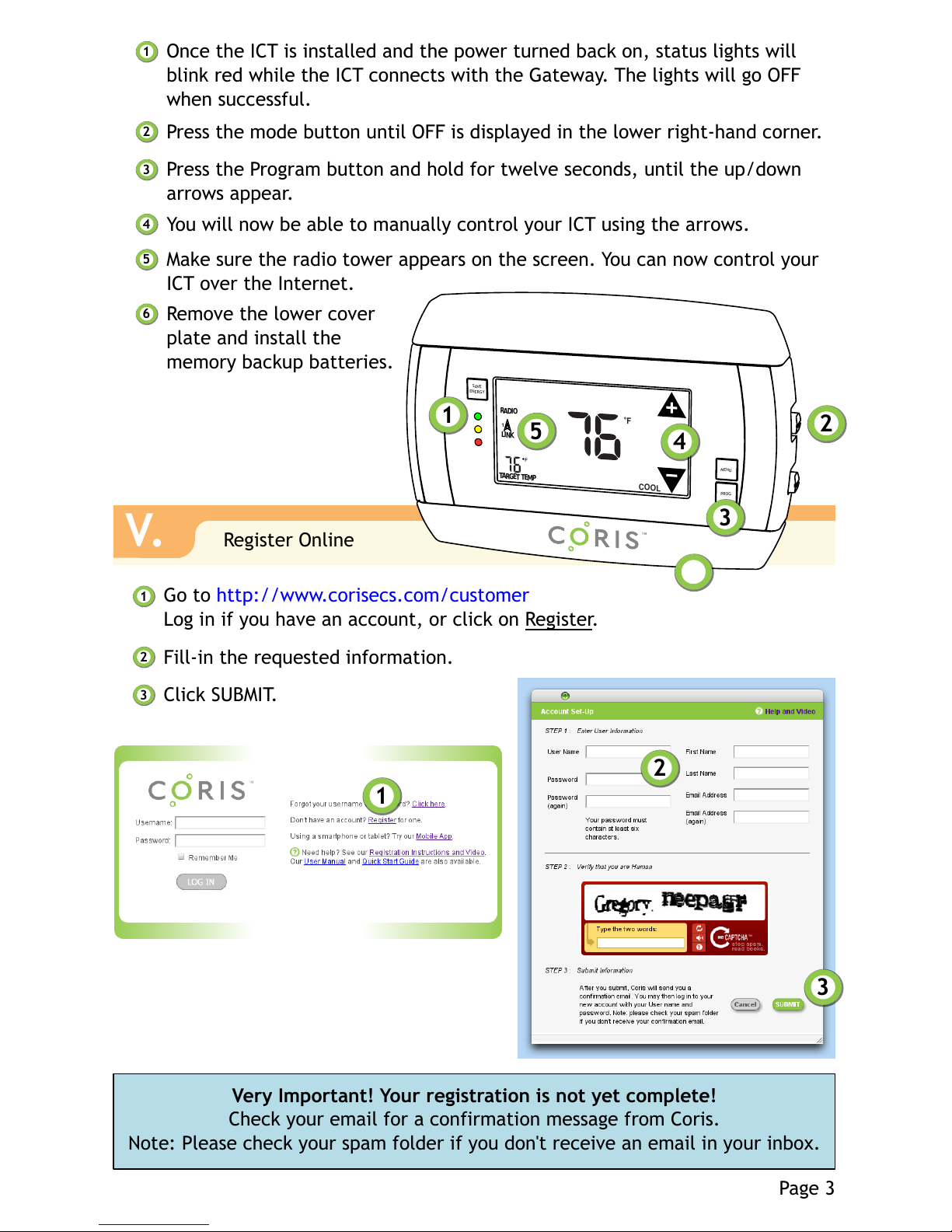
Once the ICT is installed and the power turned back on, status lights will
blink red while the ICT connects with the Gateway. The lights will go OFF
when successful.
Press the mode button until OFF is displayed in the lower right-hand corner.
Press the Program button and hold for twelve seconds, until the up/down
arrows appear.
2
1
3
You will now be able to manually control your ICT using the arrows.
4
Make sure the radio tower appears on the screen. You can now control your
ICT over the Internet.
5
Page 3
V.
Register Online
Go to http://www.corisecs.com/customer
Log in if you have an account, or click on Register.
Fill-in the requested information.
Click SUBMIT.
2
1
3
Very Important! Your registration is not yet complete!
Check your email for a confirmation message from Coris.
Note: Please check your spam folder if you don't receive an email in your inbox.
1
2
3
F
LINK
RADIO
TARGET TEMP
1
COOL
PROG
1
2
3
5
MENU
SAVE
ENERGY
4
Remove the lower cover
plate and install the
memory backup batteries.
6
6
Page 4
BuildingStaff
28 = Internet Controlled Thermostat
Room405
My new Coris smart thermostat
Room405
Module: Room405
Room405
1
2
3
Heating Target Temperature:
Cooling Target Temperature:
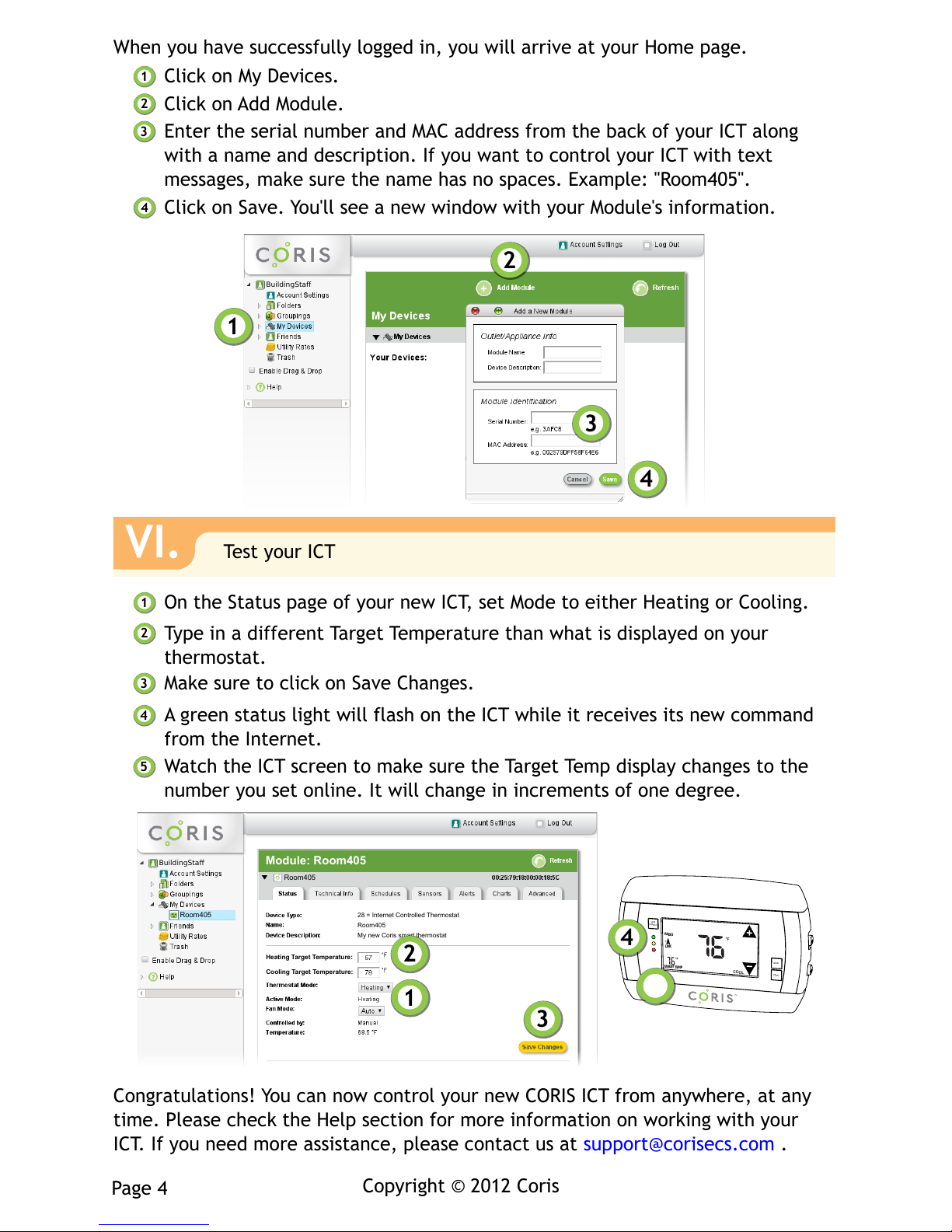
When you have successfully logged in, you will arrive at your Home page.
Click on My Devices.
Click on Add Module.
Enter the serial number and MAC address from the back of your ICT along
with a name and description. If you want to control your ICT with text
messages, make sure the name has no spaces. Example: "Room405".
2
1
3
Click on Save. You'll see a new window with your Module's information.
4
2
1
BuildingStaff
3
4
VI.
Test your ICT
On the Status page of your new ICT, set Mode to either Heating or Cooling.
Type in a different Target Temperature than what is displayed on your
thermostat.
Make sure to click on Save Changes.
2
1
3
A green status light will flash on the ICT while it receives its new command
from the Internet.
4
Watch the ICT screen to make sure the Target Temp display changes to the
number you set online. It will change in increments of one degree.
5
Congratulations! You can now control your new CORIS ICT from anywhere, at any
time. Please check the Help section for more information on working with your
ICT. If you need more assistance, please contact us at support@corisecs.com .
Copyright © 2012 Coris
Page 4
$Id: page4.svg 4844 2012-03-06 22:28:10Z martini $
F
LINK
RADIO
TARGETTEMP
1
COOL
PROG
MENU
SAVE
ENERGY
4
5
 Loading...