

Page 1

8600 Smart Routers
8665 Smart Router FP7.0
Reference Manual
76.8670-40128B
14.12.2015
Page 2
Document Information
Revision History
Document
No.
Date
Description of Changes
76.867040128B
14.12.2015
- Cautionary note regarding cable connections added to ch.
2.3.4 Timing Block, 2.5.3 Console Port,and2.5.4 External Alarm
Interface.
- Restriction regarding maximum current usage added as a footnote to
‘Power input specification’ row in ch. 6.1 8665 Smart Router Technical
Specifications.
76.867040128A
25.05.2015
Initial release of the document for 8665 Smart Router FP7.0.
This revision of the manual documents the following network element and the corresponding
feature pack or higher.
8665 Smart Router FP7.0
If a different feature pack of 8600 products, please refer to the relevant product document
program on the Tellabs and Coriant Portal by navigating to www.portal.tellabs.com > Product
Documentation > Data Networking > Tellabs 8600 Smart Routers > Technical Documentation.
© 2015 Coriant. All rights reserved.
This manual is protected by U.S. and international copyright laws, conventions and treaties. Your right to use this manual is
subject to limitations and restrictions imposed by applicable licenses and copyright laws. Unauthorized reproduction, m odification,
distribution, display or other use of this manual may result in criminal and civil penalties.
The specifications and information regarding the products in this manual are subject to change without notice. All statements,
information, and recommendations in this manual are believed to be accurate but are presented without warranty of any kind,
express or implied. Users must take full responsibility for their application of any products.
Adobe
®
Reader®are registered trademarks of Adobe Systems Incorporated in the United States and/or other countries.
8600 Smart Routers 76.8670-40128B
8665 Smart Router FP7.0 Reference Manual © 2015 Coriant.
2
Page 3

Document Information
Terms and Abbreviations
Term Explanation
ASIC Application Specific Integrated Circuit
BFD Bidirectional Forwarding Detection
BGP-4 Border Gateway Protocol version 4
BMP Broadband Management Protocol. A communication protocol which is used between
8600 network elements and 8000 network manager.
BSC Base Station Controller
CAC Connection Admission Control
CCN Configuration Change Notification
CDC Control and DC Power Card
CES Circuit Emulation Service
CLI Command Line Interface
Control card The control card in the 8600 system consists of a Control and DC Power Card CDC
(used in 8630 Smart Router and 8660 Smart Router), Switching and Control Module
SCM (used in 8611 Sma rt Router). In 8000 Intelligent Networ
k Manager and CLI
referred to as unit.
CPU Central Processor Unit
CSMA/CD Carrier Sense Multiple Access/Collision Dete
ct
CU Control functionality (used in 8615 Smart Router and 8665 Smart Router)
ECMP Equal Cost Multi Path routing
EEPROM Electrically Erasable Programmable
Read Only Memory
EMC Electromagnetic Compatibility
EMI ElectroMagnetic Interference
ERM Electromagnetic Compatibility
and Radiospectrum Matters
ESMC Ethernet Synchronization Message Channel
Fan One fan in a fan module
Fan Module A module consisting of two
or more fans, the mechanics and possibly the control
electronics
FIFO First In First Out memory
FLASH Electrically erasa
ble and programmable memory type
FMC Fixed m obile convergence
FTP File Transfer Protocol
FTP Foil S hielded Tw
isted Pai r
GND Ground
GUI Graphical User Interface
76.8670-40128B 8600 Smart Routers
© 2015 Coriant. 8665 Smart Router FP7.0 Reference M anual
3
Page 4

Document Information
I2C Bidirectional two-wire serial bus that provides a communication link between
integrated circuits (ICs).
IEEE Institute o f Electrical and Electronics Engineers
IP Internet Protocol
IRB Integrated Routing and Bridging
IS-IS Intermediate System to Intermed iate System (Interior Gateway Protocol)
I-TEMP Industrial Temperature Range
ITU-T International Telecommunication Union - Telecom Standardization Sector
LDP Label Distribution Protocol
LED Light-Emitting Diode
LER Label Edge Router
Line card The line card in the 8600 system consists of an Ethernet Line Card (ELC1), Interface
Module Concentrator (IFC) and up to two Interface Modules (IFMs) (used in 8630
Smart Router and 8660 Smart Router). In 8000 Intelligent Network Manager and
CLI referred to as unit.
Line unit The line unit in the 8665 Smart Router is the basic building block for the element.
One line unit contains always t he traffic functionality (LU) and, optionally control
functionality (CU).
LU Traffic functionality (used in 8615 Smart Router and 8665 Smart Router).
LU1 Line Unit in 8665 Smart Router.
LSP Label Switched Path
LSR Label Switch Router
LTE Long Term Evolution
MAC Media Access Control Sublayer of Data Link Layer
MP-BGP Multiprotocol Border Gateway Protocol
MPLS Multiprotocol Label Switching
MTU Maximum Transfer/Transmission Unit
NE Network Element
NEBS Network Equipment Building Systems
NRTL Nationally Recognized Testing Laboratory
OAM Operation, Administration and Maintenance
OSPF Open Shortest Path First
OSS Operating Support System
PCML Pseudo Current Mode Logic
PFC Power Factor Correction Circuit
PHY Physical Layer Device
PIM Power Input Module
PLL Phase Locked Loop
PPP Point-to-Point Protocol
8600 Smart Routers 76.8670-40128B
8665 Smart Router FP7.0 Reference Manual © 2015 Coriant.
4
Page 5

Document Information
PPS Pulse-per-Second
PSN Packet Switch Network
PSU Power Supply Unit
PWE3 Pseudowire Edge to Edge Emulation
PWM Pulse Width Modulation
QoS Quality of Service. A way of guaranteeing a defined performance through the
network. Implementation of QoS in the network means specific bandwidth, latency,
jitter and loss guarantees per each traffic flow.
RAN Radio Access Network
RFC Request For Comments
RIB Routing Information Base
RISC Reduced Instruction Set Computer
RNC Radio Network Controller
RSVP-TE Resource Reservation Protocol – Traffic Engineering
RTC Real Time Clock
SCI Station Clock Input
SCO Station Clock Output
SDH Synchronous Digital Hierarchy
SDRAM Synchronous Dynamic Random Access Memory
SEC Synchronous Equipment Clock
SFP Small Form-Factor Pluggable. A transceiver type used in 8600 IFMs.
SM Single Mode
SNMP Simple Network Management Protocol
SONET Synchronous Optical Network
SSM Synchronization Status Messages
STM Synchronous Transfer Mode
STP Shielded Twisted Pair
SU1 Switch Unit in 866 5 Smart Router
VCCV Virtual Circuit Connectivity Verification
VLAN Virtual LAN (Local Area Network)
VPN Virtual Private Network
VRF VPN R outing and Forwarding Table
VRRP Virtual Router Redund ancy Protocol
VSI Virtual Switching Instances
WFQ Weighted Fair Queueing
WiMAX Worldwide Interoperability for Microwave Access
WRED Weighted Random Early Detection
76.8670-40128B 8600 Smart Routers
© 2015 Coriant. 8665 Smart Router FP7.0 Reference M anual
5
Page 6

Document Information
XFP 10-Gigabit Small Form-Factor Pluggable. A transceiver type used in 860 0 ELC1
line card.
Compliance Statement
Hereby, Coriant Oy declares that this product is in compliance with the essential requirements and
other relevant provisions of Directive 1999/5/EC and Directive 2011/65/EU.
FCC Notification Statement
Federal Communications Commission (FCC) Rules require that you be notified of the following:
This equipment has been tested and found to comply with the limits for a Class A digital device,
pursuant to Part 15 of the FCC rules. These limits are designed to provide reasonabl e protection
against harmful interference in a residential installation. This equipment generates, uses and can
radiate radio frequency energy and, if n ot installed and used in accordance with the instructions,
may cause harmful interference to radio com m uni cations. H owever, there is no guarantee that
interference w ill not occur in a particular installation. If this equipment does cause harmful
interference to radio or television reception, which can be determined by turning the equipment off
and on, the user is encouraged to try to correct the interference by one or more of the following
measures:
• Reorient or relocate the receiving antenna.
• Increase the separation between the equipment and the receiver.
• Connect the equipment into an outlet on a circuit different from that to which the receiver is
connected.
• Consult the dealer or an experienced radio/TV technician for help.
Changes or modifications not expressly approved by Coriant Operations, Inc., in writing can void
the user’s authority to operate the equipment.
8600 Smart Routers 76.8670-40128B
8665 Smart Router FP7.0 Reference Manual © 2015 Coriant.
6
Page 7

Table of Contents
Table of Contents
About This Manual............................................................................................................10
Objectives....................................................................................................................................................................... 10
Audience......................................................................................................................................................................... 10
8600 Smart Routers Technical Documentation.............................................................................................................. 10
Document Conventions.................................................................................................................................................. 13
Documentation Feedback............................................................................................................................................... 13
8600 Smart Routers Discontinued Products ..................................................................14
Safety Notes ......................................................................................................................15
Intended Purpose ............................................................................................................................................................ 15
Class 1 Laser Product ..................................................................................................................................................... 15
Jewelry Removal ............................................................................................................................................................ 16
Installation and Maintenance ......................................................................................................................................... 16
Lightning Activity .......................................................................................................................................................... 18
1 8665 Smart Router Overview......................................................................................19
1.1 Subrack ................................................................................................................................................................ 19
1.1.1 Backplane ............................................................................................................................................ 20
1.1.2 Unit Slots ............................................................................................................................................. 21
1.1.3 Cooling ................................................................................................................................................ 23
1.2 8665 Smart Router Powering .............................................................................................................................. 25
1.3 8665 Smart Router Power Consumption ............................................................................................................. 26
1.4 Synchronization ................................................................................................................................................... 27
1.5 8665 Smart Router Redundancy.......................................................................................................................... 27
1.5.1 Control Redundancy ............................................................................................................................ 27
1.5.2 Line Unit Redundancy......................................................................................................................... 28
1.5.3 Switch Unit Redundancy ..................................................................................................................... 28
1.5.4 Redundancy Terminology.................................................................................................................... 28
2 Line Unit (LU1).............................................................................................................29
2.1 Overview ............................................................................................................................................................. 29
2.2 Main Features ...................................................................................................................................................... 29
76.8670-40128B 8600 Smart Routers
© 2015 Coriant. 8665 Smart Router FP7.0 Reference M anual
7
Page 8

Table of Contents
2.3 Operation ............................................................................................................................................................. 30
2.3.1 CPU Subsystem ................................................................................................................................... 30
2.3.2 NPU Subsystem ................................................................................................................................... 31
2.3.3 FPGA Subsystem ................................................................................................................................. 31
2.3.4 Timing Block ....................................................................................................................................... 31
2.3.5 Backplane Data Links.......................................................................................................................... 33
2.3.6 Power Supply....................................................................................................................................... 33
2.3.7 Test Features ........................................................................................................................................ 33
2.4 Interfaces ............................................................................................................................................................. 34
2.5 Front Panel........................................................................................................................................................... 35
2.5.1 CFP2, SFP+ and SFP Transceivers ..................................................................................................... 35
2.5.2 USB Port.............................................................................................................................................. 36
2.5.3 Console Port ........................................................................................................................................ 36
2.5.4 External Alarm Interface ..................................................................................................................... 37
2.6 LU1 LEDs............................................................................................................................................................ 38
2.6.1 LU1 Status LEDs ................................................................................................................................. 38
2.6.2 LU1 Ethernet LEDs ............................................................................................................................. 38
2.7 Cabling................................................................................................................................................................. 39
2.8 Laser Safety ......................................................................................................................................................... 39
2.9 LU1 Cooling ........................................................................................................................................................ 39
3 Switch Unit (SU1) ........................................................................................................ 40
3.1 Overview ............................................................................................................................................................. 40
3.2 Main Features ...................................................................................................................................................... 40
3.3 Operation ............................................................................................................................................................. 40
3.3.1 CPU Subsystem ................................................................................................................................... 41
3.3.2 FPGA Subsystem ................................................................................................................................. 42
3.3.3 Control Ethernet Switch ...................................................................................................................... 42
3.3.4 Backplane Data Links.......................................................................................................................... 42
3.3.5 Power Supply....................................................................................................................................... 42
3.3.6 Test Features ........................................................................................................................................ 42
3.4 Front Panel........................................................................................................................................................... 43
3.4.1 SU1 Status LEDs ................................................................................................................................. 43
4 Power Input Module .................................................................................................... 45
4.1 Overview ............................................................................................................................................................. 45
4.2 Operation ............................................................................................................................................................. 45
4.3 Front Panel and Connectors................................................................................................................................. 46
4.4 Input Fault Detection and LEDS ........................................................................................................................ 46
4.5 Cabling................................................................................................................................................................. 46
5 Pluggable Transceivers ..............................................................................................47
6 Technical Specifications............................................................................................. 48
8600 Smart Routers 76.8670-40128B
8665 Smart Router FP7.0 Reference Manual © 2015 Coriant.
8
Page 9

Table of Contents
6.1 8665 Smart Router Technical Specifications....................................................................................................... 48
6.2 LU1 Technical Specifications.............................................................................................................................. 52
6.3 SU1 Technical Specifications .............................................................................................................................. 52
6.4 8665 Smart Router DC48 Power Input Module Technical Specifications .......................................................... 53
6.5 8665 Smart Router Fan Module Technical Specifications .................................................................................. 53
6.6 Timing Block Technical Specifications ............................................................................................................... 53
End of Life Treatment ....................................................................................................... 55
76.8670-40128B 8600 Smart Routers
© 2015 Coriant. 8665 Smart Router FP7.0 Reference M anual
9
Page 10
About This Manual
About This Manual
This section discusses the objectives and inten ded audience of this manual, 8665 Smart Router
Reference M anual and consists of the following sections:
• Objectives
• Aud ience
• 8600 Smart Routers Technical Documentation
• Docu men t Conventions
• Documentation Feedback
Objectives
The goal is to describe the network element features of 8665 Smart Router.
Audience
This manual is intended for system specialists and personnel involved in network planning.
8600 Smart Routers Technical Documentation
The document numbering scheme consists of the document ID, indicated by numbers, and the
document revision, indicated by a letter. The references in the Related Documentation table below
are generic and include only the document ID. To make sure the references point to the latest
available document versions, please refer to the relevant product document program on the Tellabs
and Coriant Portal by navigating to www.portal.tellabs.com > Product Documentation & Software
> Data Networking > 8600 Smart Routers > Technical Documentation.
Document Title Description
8600 Smart Routers
ATMandTDMConfiguration
Guide
(76.8600-50110)
Provides an overview of 8
600 NEs PWE3 applications,
including types, Single-Segment and Multi-Segment; PWE3
Redundancy; ATM applica
tions, including PWE3 tunnelling,
Traffic Management, Fault Management OAM, protection a nd
TDM applications as we
ll as instructions on how to configure
them with CLI.
8600 Smart Routers
Boot and Mini-Applications
Embedded Software Release Notes
(76.8600-50108)
Provides information related to the boot and mini-applications
software of 8605 Smart Router, 8607 Smart Router, 8609
Smart Router, 8611 Smart Router, 8620 Smart Router, 8630
Smart Router and 8660 Smart Router as well as the installation
instructions.
8600 Smart Routers
CLI Commands Manual
(76.8600-50117)
Provides commands available to configure, monitor and maintain
8600 system with CLI.
8600 Smart Routers 76.8670-40128B
8665 Smart Router FP7.0 Reference Manual © 2015 Coriant.
10
Page 11
About This Manua l
Document Title Description
8600 Smart Routers
Embedded Software Release Notes
8600 Smart Routers SR7.0 Embedded Software Release Notes
(76.8670-50177) for the following products:
• 8602 Smart Router FP7.0
• 8609 Smart Router and 8611 Smart Router FP7.0
• 8615 Smart Router FP7.0
• 8630 Smart Router and 8660 Smart Router FP7.0
• 8665 Smart Router FP7.0
8600 Smart Routers
Equipment Management
Configuration Guide
(76.8600-50118)
Provides an overview of 8600 system HW inventory, software
management, equipment protection 1+1 (CDC and SCM) as well
as instructions on how to configure them with CLI.
8600 Smart Routers
Ethernet Configuration Guide (76.
8600-50133)
Provides an overview of 8600 system Ethernet applications,
including interfaces; Ethernet forwarding (MAC Switching,
Ethernet PWE3, IRB, VLAN, VPLS); Ethernet OAM; LAG;
ELP as well as instructions on how to configure them with CLI.
8600 Smart Routers Smart Routers
Fault Management Configuration
Guide (76.8600-50115)
Provides an overview of 8600 system fault management,
including fault source, types and status as well as instructions on
how to configure it with CLI.
8600 Smart Routers
Frame Relay Configuration Guide
(76.8600-50120)
Provides an overview of 8600 system Frame Relay applications,
including interfaces; Performance Monitoring; protection; Traffic
Management as well as instructions on how to configure them
with CLI.
8600 Smart Routers
Hardware Installation Guide
(76.8600-40039)
Provides guidance on mechanical installation, cooling,
grounding, powering, cabling, maintenance, commissioning and
ESW downloading.
8600 Smart Routers
Interface Configuration Guides
The Interface Configuration Guides provides an overview
of the
8600 NEs interface functions, including NE supported interface
types and equipping; interface features; configuratio
n options and
operating modes; fault management; performance monitoring;
interface configuration layers and port protocol
saswellas
instructions on how to configure them with CLI. The following
interface configuration guides are available:
• 8600 Smart Routers Network Interfaces Configuration
Guide (76.8600-50161) (for 8602 Smart Router, 8
615 Smart
Router and 8665 Smart Router)
• 8609 Smart Router and 8611 Smart Router FP7.
0 Interface
Configuration Guide (76.8670-50179)
• 8600 Smart Routers FP7.0 Interface Configu
ration Guide
(76.8670-50180) (for 8630 Smart Router and 8660 Smart
Router)
8600 Smart Routers
IP Forwarding and Traffic
Management Configuration Guide
(76.8600-50122)
Provides an overview of 8600 NEs IP, forwarding and traffic
management functionality, including: IP addressing; IP hosting
(ARP, DHCP); IP routing (static); ACL; Differentiated Services
(Policing, Queue Management, Shaping) as well as instructions
on how to configure them with CLI.
8600 Smart Routers
Management Communications
Configuration Guide
(76.8600-50125)
Provides an overview of 8600 system management
communications functions, including communication protocols:
BMP; FTP; RADIUS; SNM P; SSH; TELNET as well as
instructions for configuring them with CLI.
76.8670-40128B 8600 Smart Routers
© 2015 Coriant. 8665 Smart Router FP7.0 Reference M anual
11
Page 12
About This Manual
Document Title Description
8600 Smart Routers
Mobile Optimization Configuration
Guide (76.8600-50100)
Provides an overview of 8600 system Mobile Optimization
applications as well as instructions on how to configure them
with CLI.
8600 Smart Routers
MPLS Applications Configuration
Guide (76.8600-50123)
Provides an overview of 8600 NEs MPLS applications (including
FRR (one-to-one and facility backup); LDP; protection and
Traffic Engineering), MPLS-TP applications (including OAM,
linear protection), S-MPLS applications as well as instructions
on how to configure them with CLI.
8600 Smart Routers
Performance Counters Reference
Guide (76.8600-50143)
Provides an overview of 8600 system supported performance
counters.
8600 Smart Routers
Reference Manuals
The reference manuals describe the 8600 network element
features including:
• NE enclosure, baseboard, power supply modules, and
interfaces in 8602 Smart Router FP7.0 Reference Manual
(76.8670-40130)
• NE enclosure, baseboard, power supply modules, interfaces
and physical LM types in 8609 Smart Router FP7.0 Reference Manual
• NE enclosure, baseboard, power supply modules, SCMs, HM
and LM types in 8611 Smart Router FP7.0 Reference M anual
• NE enclosure, baseboard, power supply modules, and interfaces in 8615 Smart Router FP7.0 Reference M anual
(76.8670-40132)
• NE subrack, fan modules, CDCs, line cards and IFMs in 8630
Smart Router FP7.0 Reference Manual
• NE subrack, fan modules, CDCs, line cards and IFMs in 8660
Smart Router FP7.0 Reference Manual
• NE subrack, fan modules, line unit and switch unit in 8665
Smart Router FP7.0 Reference Manual (76.8670-40128)
8600 Smart Routers
Routing Protocols Configuration
Guide (76.8600-50121)
Provides an overview of 8600 NEs routing protocols, including
BFD; BGP; BGP MP; ECMP; IS-IS; OSPF and VRRP as well as
instructions on how to configure them with CLI.
8600 Smart Routers
Scalability Reference Manual
(76.8600-50160)
Provide a summary of tested scalability limits of the 8600 Smart
Routers.
8600 Smart Routers
SNMP MIB Support
(76.8600-50116)
Describes SNMP MIB support by the 8600 NEs and
provides
information on the supported objects a nd traps. For further
information on SNMP MIBs, see the related RF
Cs.
8600 Smart Routers
Statistic Counters Reference Guide
(76.8600-50142)
Provides an overview of 8600 system supported statistic counters.
8600 Smart Routers
Synchronization Configuration
Guide (76.8600-50114)
Provides an overview of 8600 NEs synchronization functionality,
including physical layer F requency Synchronization (SEC, EEC);
PTP Frequency Synchronization; Phase-Time Synchronization
(L2 and L3 applications) as well as instructions on how to
configure them w ith CLI.
8600 Smart Routers 76.8670-40128B
8665 Smart Router FP7.0 Reference Manual © 2015 Coriant.
12
Page 13
About This Manua l
Document Title Description
8600 Smart Routers
Test and Measurement Configuration
Guide (76.8600-50124)
Provides an overview of 8600 NEs measurement and connectivity
verification tools, including Ethernet loopback; IP ping and
traceroute; MAC swap loopback; MPLS ping and traceroute;
PLT; PWE3 loopback; VCCV (BFD, LSP ping) as well as
instructions on how to configure them with CLI.
8600 Smart Routers
VPNs Configuration Guide
(76.8600-50128)
Provides an overview of 8600 system virtual private network
(VPN) layer 3 applications as well as instructions on how to
configure them w ith CLI.
8000 Intelligent Network Manager
Online Help
Provides instructions on how different operations are performed
with the 8000 Intelligent Network Manager. Describes also
different parameters and controls of the 8000 Intelligent Network
Manager dialogs and windows.
Note that the Online Help is not available on the Portal but it is
incorporated in the 8000 Intelligent Network Manager.
Document Conventions
This is a note symbol. It emphasizes or supplements information in the do
cument.
This is a caution symbol. It indicates that damage to equipment is possible if the instructions
are not followed.
This is a warning symbol. It indicates that bodily injury is possible if the instructions are not
followed.
Documentation Feedback
Please contact us to suggest improvements or to report errors in our documentation:
Email: fi[email protected]
76.8670-40128B 8600 Smart Routers
© 2015 Coriant. 8665 Smart Router FP7.0 Reference M anual
13
Page 14

8600 Smart Routers Discontinued Products
8600 Smart Routers Discontinued Products
8600 Smart Routers Manufacture Discontinued (MD) notifications are available on the Tellabs
and Coriant Portal, www.portal.tellabs.com > Product Documentation & Software > Data
Networking > [8600 Smart Routers product name] > Product Notifications.
8600 Smart Routers 76.8670-40128B
8665 Smart Router FP7.0 Reference Manual © 2015 Coriant.
14
Page 15
Safety Notes
Safety Notes
This chapter lists safety notes and their translations for 8600 network elements.
Intended Purpose
The equipment shall be used only fo r its intended purpose.
Das Gerät soll nur für den vorgesehen Einsatzzweck verwendet werden.
CAUTION: Do not insert an RJ-11 (telephone) plug into Ethernet or
E1/T1 ports. Equipment
damage may result.
ACHTUNG: Stecken Sie keine RJ-11 (Telefon) Stecker in die Ethern
et oder E1/T1 Anschlüsse
da dieses zu einer Beschädigung des Gerätes führen kann.
CAUTION: Do not climb on or stand on the 8600 network element. Neither the network element
nor its enclosure is designed to support the weight of a person.
ACHTUNG: Ste igen Sie oder stellen Sie sich nicht auf das 8600 Netzwerk Eleme nt. Weder
des Netzwerk Element noch da s Gehäuse sind dafür ausgelegt worden das Gewicht einer
Person zu tragen.
Class 1 Laser Product
Class 1 laser product.
Laserprodukt der Klasse 1.
WARNING: No other types of lasers can be used than supplied an d approved by Coriant. If
other types are used, th
e laser class and compliance to laser safety and EMC standards
must be checked.
WARNUNG: Verwenden Sie
keine anderen als die von Corian t gelieferten und zugelassenen
Lasertypen. Falls Sie andere Typen verwenden, müs sen die Laserklasse und die Einhaltung
von Laser sicherheits-
undEMV-Normengeprüftwerden.
76.8670-40128B 8600 Smart Routers
© 2015 Coriant. 8665 Smart Router FP7.0 Reference M anual
15
Page 16
Safety N otes
WARNING: Install only l asers that have been demonstrated to meet Class 1 eye safe levels by
a Nationally recognized Authority such as The Food and Drug administration's 21CFR1040
Laser Energy Source, UL 60950-1 Information Technology equipment and European norms
EN60950-1, EN60825-1 and EN60825-2. Failure to use laser transceivers which meet these
standards could result in eye damage to users or service personnel working around the
equipment.
WARNUNG: Installieren Sie nur Laser der Klasse 1 die die Augenschutz Richtlinien
der staatlich anerkannten Organisationen wie z.B. The Food and Drug administration’s
21CFR1040 Laser Energy Source, UL 60950-1 Information Technology equipment oder die
Europa Normen EN60950-1, EN60825-1 un d EN60825-2 erfüllen. Laser die diese Standards
nichterfüllenkönnenzuVerletzungenanAugendesBenutzersunddesServicePersonals
das in der Nähe der Geräte arbeitet führen.
WARNING: Optic operation should be verified by observing the status LEDs. Do not look into
the laser or fiber to verify operation.
WARNUNG: Überprüfen Sie die Funktionstüchtigkeit der Optischen Einheit anhand der Status
LED. Schauen Sie nie in den Laser oder die Glasfaser um die Funktion zu prüfen.
WARNING: Because invisible radiation may be emitted from the aperture of the port when no
fiber cable is connected, avoid exposure to radiation and do not stare into open apertures.
WARNUNG: Aus der Stecker Öffnung können unsichtbare Strahlen emittieren wenn kein
Glasfaserkabel angeschlossen ist. Vermeiden Sie es sich den Strahlungen auszusetzen und
starren Sie nicht in die Öffnungen.
Jewelry Removal
WARNING: Before working on equipment that is connected to power source, remove jewelry
(including rings, necklaces, and watches). Metal objects will heat up when connected to
power and ground and can cause serious burns or weld the metal object to the terminals.
WARNUNG: Bevor Sie an Geräten arbeiten die an eine Spannungsversorgung angeschlossen
sind, entfernen Sie all Ihren Schmuck (einschließlich Ringe, Ketten und Uhren). Metallobjekte
erhitzen sich wenn sie einen Kurzschluss zwischen Spannungsversorgung und Masse/Erdung
verursachen. Dieses kann zu schweren Verbrennungen führen oder das Anschweißen an die
Anschlussklemmen zur Folge haben.
Installation and Maintenance
WARNING: This equipment is to be installed and maintained by qualified service personnel
only.
WARNUNG: Dieses Gerät darf nur von qualifiziertem Fach- oder Servicepersonal installiert
oder gewartet werden.
8600 Smart Routers 76.8670-40128B
8665 Smart Router FP7.0 Reference Manual © 2015 Coriant.
16
Page 17
Safety Notes
CAUTION: Electrical interfaces may require external protection devices to safeguard against
overvoltages, transients, earth potential differences and/or power cross-contacts.
ACHTUNG: Elektrische Anschlü sse benötigen evtl. externe Schutzs chaltungen
um sie vor Überspannung, Einschaltspitzen, Erdpotentialunterschieden und/oder
Fremdspannungsüberlagerung zu schützen.
CAUTION: While handling the modules (Interface Modules, Line Modules, High Speed
Modules, SCM, CDC, Line Cards, Power Modules, Power Input Modules and Fan Modules) of
the 8600 network elements, always take care of proper handling, e.g. do not bend or twist
the modules, do not touch the components on the modules, take care of good ESD working
practices, do not use excessive force while inserting or removing the modules, do not drop
the modules.
ACHTUNG: Achten Sie darauf, dass Sie mit den Modulen (Schnittstellenmodulen,
Netzmodulen, Hochgeschwindigkeits-Netzmodulen, SCM, CDC, Netzkarten, Netzteilmodulen,
Netzeingangsmodulen und Lüftermodu le n) der 8600-Netzwerkelemente sorgsam umgehen
und diese nicht verbiegen oder verdrehen. Berühren Sie nicht die Bauteile auf den Modulen.
Wenden Sie beim Ein- oder Ausbauen der Module keine übermäßige Kraft an und lassen Sie
die Module nicht fallen. Beachten Sie außerdem die Arbeitsrichtlinien im Zusammenhang
mit elektrostatischer Entladung.
WARNING: For US usage: this equipment must only be used with a Nat
ionally Recognized
Testing Laboratory (NRTL) approved power supply.
WARNUNG: Für den Gebrauch in den USA: Dieses Gerät darf nur m it ei
ner von einer national
anerkannten Test Einrichtung (NTRL) zugelassenen Spannungsversorgung betrieben werden.
WARNING: Read the installation instructions before you connect the system to its power
source.
WARNUNG: Lesen Sie d ie Installationsanweisungen bevor Sie das System an die
Spannungsversorgung anschließen.
WARNING: When installing or performing maintenance on the equipment, the ground
connection must always be made first. Never operate or maintain an ungrounded e quipment.
WARNUNG: Bei der Installation oder b ei Wartungsarbeiten am Gerät muss die Masse/Erdung
immer als erstes angeschlossen werde n. Betreiben Sie oder arbeiten Sie niemals an einem
Gerät das nicht geerdet ist.
76.8670-40128B 8600 Smart Routers
© 2015 Coriant. 8665 Smart Router FP7.0 Reference M anual
17
Page 18

Safety N otes
Lightning Activity
WARNING: Do not work on the system or connect or disconnect cables during periods of
lightning activity.
WARNUNG: A rbeiten Sie während eines Gewitters mit Blitzschlag nicht an dem Gerät oder
schließen Sie auch keine Kabel an bzw. trennen Sie keine ab.
8600 Smart Routers 76.8670-40128B
8665 Smart Router FP7.0 Reference Manual © 2015 Coriant.
18
Page 19

1 8665 Smart Router Overview
1 8 665 Smart Router Overview
8665 Smart Router is a cost efficient, 900 Gbp/s full duplex IP/MPLS router for pure packet
networks providing Ethernet interfaces from 1 to 100 Gbp/s. It is designed to be deployed in
medium-sized aggregation and large mobile macro sites as well as controller and S-GW sites in
technically advanced all-IP networks. It provides the flexibili ty and capabilities to serve all-IP
mobile and fixed networks inc lud ing applications ranging from traditional consumer, enterprise and
machine-to-machine connectivity to cloud networking needs. It has the interface density, throughput
and cost effectiveness to meet the needs of fast growing data services while maintaining high
quality for low latency voice traffic.
1.1 Subrack
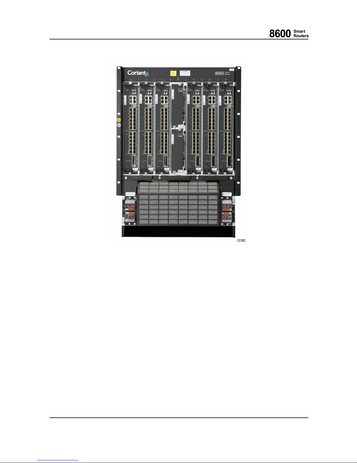
The 8665 Smart Router subrack can be installed into 600 mm deep 19” rack. The outer dim ensions
ofthesubrackare445mm/17.51inx666mm/26.22inx445mm/17.51in(wxhxd),thewidth
with the integrated side adapter front flange is 483 mm/19.01 in.
The 8665 Smart Router is 15U high and designed for front to back airflow installations. The 8665
Smart Router subrack allows the subrack and backplane serial num bers to be read by the software
from an EEPROM device, thereby making them visible on 8000 Intelligent Network Manager and
CLI.
76.8670-40128B 8600 Smart Routers
© 2015 Coriant. 8665 Smart Router FP7.0 Reference M anual
19
Page 20
1 8665 Smart Router Overview
Fig. 1 Equipped 8665 Smart Router Subrack
1.1.1 Backplane
8665 Smart Router uses a dual backplane architecture, which allows that all the cards are accessible
from the front panel. The backside of the subrack has a metal cover and all the interface connectors
are located on the front side. The signal backplane itself is passive and only provides connectors
and signal paths for high speed data packet transfer. Power distribution and low speed signaling
among the cards is handled by a separate backplane. The power backplane contains some passive
components for line termination, signal integrity purposes and the identification EEPROM.
The backplane data transmission architecture is based on differential signals in which the switch
cards are the center points for a dual star topology in a redundant configuration. There is also a
separate internal communication dual star bus topology between the units in the NE. This separate
control bus assures that the NE internal control is not lost even if the forwarding plane network
processors have problems. The other buses are power, synchronization (clock), fan module co ntrol
and unit presence busses.
8600 Smart Routers 76.8670-40128B
8665 Smart Router FP7.0 Reference Manual © 2015 Coriant.
20
Page 21
1 8665 Smart Router Overview
1.1.2 Unit Slots
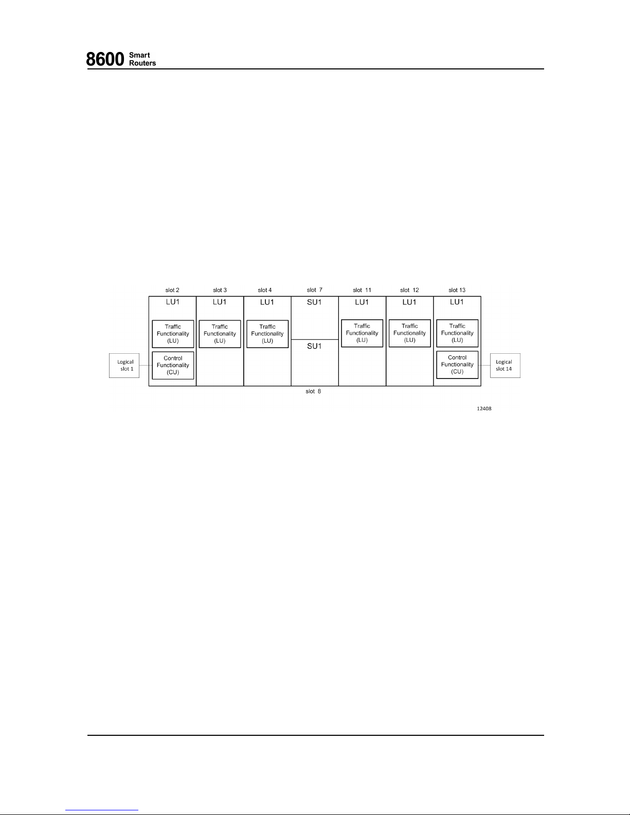
There are 8 slots in 8665 Smart Router, of which 6 (slots 2...4 on the left side and slots 11...13 on the
right side) are available for the line units with user traffic interfaces. The central slot, divided into
two slots (7 and 8) is reserved for the two switch units, SU1s.
At least one SU1 must be installed into one of the switch slots for the 8665 Smart Router t o be
operational. Equipping the second slot with an SU 1 is highly recommended, although the need for it
depends on protection requirements. All units are hot-removable and hot-insertable.
Besides the physical slots, logical slots 1 and 14 are reserved for the control functionality running on
the line units. Refer to chapter Control Functionality (CU) for more information.
Fig. 2 8665 Smart Rou ter Slot Distribution
8665 Smart Router Line Unit (LU1)
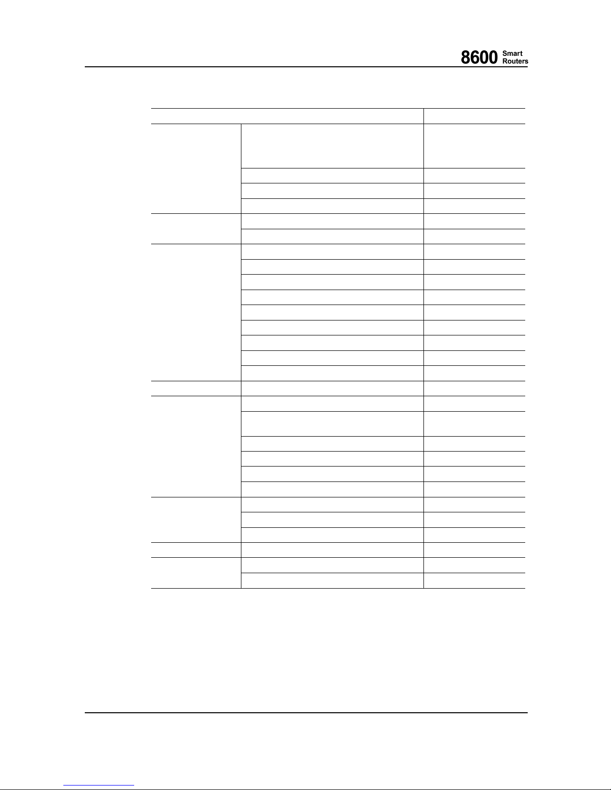
8665 Smart Router line unit LU1 has the following interfaces:
• 1x100GE (CPF2) + 24x1/10GE ( SFP+/SFP) with two user selectable op erating modes:
• 1x100G E (CPF2) + 14x1 /10 GE (SFP+/SFP)
• 24x1/1 0GE SFP+/SFP
LU1 contains the following f unction al features:
• High sp eed data links with the switch unit
• Line interfaces
• Local power supply
• CPU for control plane processing
• Network processor for packet processing
• Timing interfaces and stable OCXO clock
76.8670-40128B 8600 Smart Routers
© 2015 Coriant. 8665 Smart Router FP7.0 Reference M anual
21
Page 22
1 8665 Smart Router Overview
LU1 Features
Feature
LU1 Support
Throughput capacity 130 Gbps/s with one
operational SU1
200 Gbps/s w ith two
operational SU1s
IPv4 routing Supported
MPLS switching Supported
Forwarding
Ethernet MAC switching Supported
IP VPN
Supported
Services
Pseudowire attachment circuits Supported
7DiffServtraffic classes (EF, AF, BE, CS) Supported
7 queues per port
Supported
VLAN queuing Supported
Ingress packet policers Supported
RED/WRED queue management Supported
Tail drop queue management Supported
Strict priority and WFQ scheduling Supported
Egress port queue shaping
—
Traffic management
VLAN shaping Supported
Synchronization Synchronous Ethernet Supported
Ethernet Link Protection (ELP) Supported
[IEEE 802.1AX] Ethernet link aggregation
(intra-IFM) (LAG)
Supported
Equal Cost Multipath (ECMP) Supported
Fast Reroute (FRR)
—
Virtual Router Redundancy Protocol (VRRP) Supported
Protection
Ethernet Pseudowire redundancy Supported
Port and layer 2 protocol statistics Supported
IP a
nd MPLS statistics
—
Statistics
VLAN statistics Supported
OAM
[IEEE 802.1ag]/[Y.1731] Ethernet OAM Supported
L3/L4 access lists SupportedMiscellaneous
Power consumption measurement Supported
Control Functionality (CU)
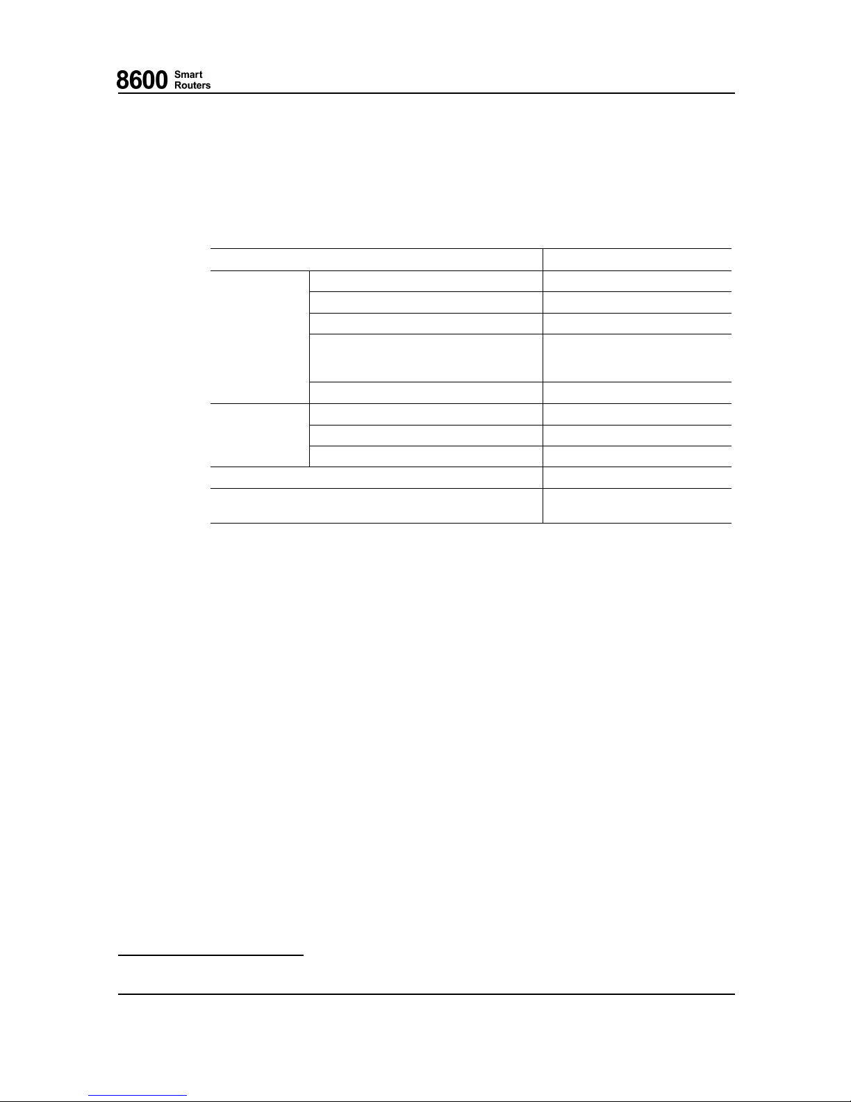
The control functionality (CU) in 8665 Smart Router is run on one or two line units, depending on
the required level of redundancy and the am ou nt of units present in the network element. Note that
the CU on the line units is a completely separate running protected process.
8600 Smart Routers 76.8670-40128B
8665 Smart Router FP7.0 Reference Manual © 2015 Coriant.
22
Page 23
1 8665 Smart Router Overview
Currently, the control functionality can be run only on the line units in slots 2 an d 13, respectively
the leftmost and rightmost line units in the network element. When both units in slots 2 and 13 are
installed, the network element is fully redundant.
Note that the timing a nd alarm interfaces should be only used from slots 2 and 13.
Control Plane Functionality Inside an LU1 Via CU
Feature
Control plane functionality
CPU cores
8 (Dual threaded 16)
Operating frequency
1666 MHz
Memory speed 1800 MHz (DDR3)
Cache memory 32K L1 I+D cache per core,
4M L2 cache in two clusters,
1M L3 cache shared
CPU
Routing memory (RIB) Approximately 3200 MB
Management Ethernet port One of the normal traffic interfaces
Serial console port Supported
Interfaces
Pulse per second (PPS) interface Supported
SD card Supported
Timing Integrated timing control functions
in baseboard
8665 Smart Router Switch Unit (SU1)
8665 Smart Router switch unit SU1 is used for packet switching inside the network element. SU1 has
two separate switches. The main data plane switch, which has a capacity of 900 Gbps, and a separate
control plane switch with a c
apacity of 90 Gbps. Although almost full data plane capacity can be
reached with one SU1, it is strongly recommended to use two SU1s in a redundant configuration, as
the traffic load will be shared between the two SU1s to enhance throughput and latency
1
.
SU1 contains the followi
ng functional features:
• High speed data links with all line units
• Local power supply
• CPU for local mana
gement
• Packet based Switch Fabric
• Node control packet switch
1.1.3 Cooling
8665 Smart Router has three hot sw appab le fan modules.
1
When there is only one SU1, packet header terminations and additions, packet size and other facto rs affect the throughput.
76.8670-40128B 8600 Smart Routers
© 2015 Coriant. 8665 Smart Router FP7.0 Reference M anual
23
Page 24
1 8665 Smart Router Overview
8665 Smart Router is a forced convection-cooled equipment. Fresh air is taken from the
bottom-front of the subrack and funneled through the units and the outlet air is led to the top-back.
Forced cooling is needed to dissipate the generated heat load and to maintain the components
within their o per a ting lim i ts.
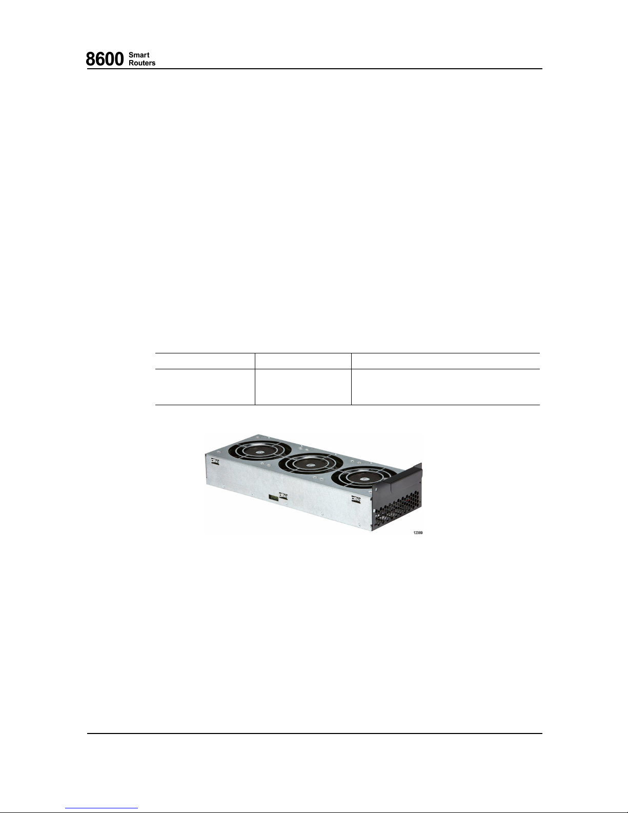
Three fan modules, located below the card shelf, blow air through the units. O ne module consists
of three parallel fans. If one of the fans fails, the other eight will maintain adequate cooling for
a limited time.
The control functionality on LU1 monitors and controls the equipment temperature by adjusting
the fan rotation speed via the backplane. The rotation speed control of the fans is based on the
temperature values measured from the components on the units in the NE. The 8665 Smart R o uter
fan module supports 16-step fan speed control. At start-up the fans are runningatfullspeeduntilthe
equipment is booted up and able to monitor the card temperatures. The operating temperature of a
unit measured by any sensor is targeted to be below +67° C/+152.6° F. I f any sensor exceeds that
value, the rotation speed of the fanswillbeadjustedtomaintainit.
There are several temperature measuring sensors on the line unit and switch unit. Some of them
measure the internal temperature of the components, while others measure the line unit temperatures
in different locations. Each sensor has its own threshold for hig h temperature warning and critical
temperature alarms. A high temperature warning is raised when the measured sensor temperature
exceeds its time-conditional threshold for over 15 minutes and immediately when the high
unconditional threshold is exceeded. The high te m perature warning indicates that the operating
ambient temperature is high and about to exceed the allowed operating range. If the warning occurs
and the equipment is not used in high ambient t emp e ratu re, it may be advisable to change the air
filter and check that there are no obstacles preventing smooth air flow. When operating at sea level
and the air filter is clean, this warning will occur at ambient near +45° C/+113° F.
If the data plane switch component temperature is exceeded the data forwarding for that SU1 is
disabled to cool down the unit, but the SU1 will still switch the N E internal communication to
protect the NE internal communication integrity.
LU1 will go to power-save mode, if the critical time-conditional threshold is exceeded for over 15
minutes or immediately, if the unconditional threshold is exceeded. LU1 will stay in power-save
mode for about 8-9 minutes before it checks if the conditions are acceptable.
LU1 Temperature Warning and Alar
m Thresholds
Sensor Name
High TimeConditional
Threshold
High
Unconditional
Threshold
Critical TimeConditional
Threshold
Critical
Unconditional
Threshold
NPU
81° C (177.8° F) 90° C (194° F) 90° C (194° F) 100° C (212° F)
CPU
81° C (177.8° F) 90° C (194° F) 90° C (194° F) 100° C (212° F)
8665 Smart Router Fan
Modules and Their Operating Voltages
8665 Smart Router fan module Operating voltage is the 48 Vdc battery voltage, fed to fan modules
via the power input modules and the backplane.
8600 Smart Routers 76.8670-40128B
8665 Smart Router FP7.0 Reference Manual © 2015 Coriant.
24
Page 25
1 8665 Smart Router Overview
Air Filtering
The air filter prevents dust from entering the subrack and keeps the cards clean in order to maintain
adequate cooling. The air filter is located in front of the fan modules in 8665 Smart Router subrack.
All empty unit slots must be shielded with a cover plate to enhance cooling, prevent EMC emissions
and dust entering the subrack.
The fan modules and air filter can be replaced on the fly without disturbing the data traffic through
the NE. Refer to the 8600 Smart Routers Hardware Installation Guide for detailed instructions.
Fan Module
One fan module has three brushless fans, three fan dri ve circuits and a com mon control logic
including a watchdog. Fuses protect the input against over-current, similarly the fan drive circui ts
have short circuit protection and limited output current in case of a fan failure. The control
functionality (CU) is able to control and monitor the operation of the fan module. If the CU fails to
control the module, the watchdog will set the fan speed to the maximum.
There is one LEDs on the front edge of the fan module.
LED Name
Color States
Power
GREEN
ON when module power is OK and a ll fans
rotating.
OFF otherwise.
Fig. 3 8665 Smart Router Fan Module
1.2 8665 Smart Router P
owering
The 8665 Smart Router can be powered with a power input module PIM with support for -48
Vdc nominal input voltage.
The NE has two s lots for PIMs. Redundant power feeding is achieved by installing a PIM in both
power module slots.
76.8670-40128B 8600 Smart Routers
© 2015 Coriant. 8665 Smart Router FP7.0 Reference M anual
25
Page 26

1 8665 Smart Router Overview
1.3 8665 Smart Router Power Consumption
The typical and maximum power consumption values of the 8665 Smart Router units and modules
are defined in the 6 Technical Specifications. These values are stored on the non-volatile memories,
EEPROMs, of the units and modules. An estimation of the power consumption of a particular NE
installation is calculated as a sum of all the units and m odules in the network element.
The network element software automatically calculates the sum of the power consumption values
from the EEPROMs of the installed units and modules in the network element. The software then
compares the power consumption sum w ith the maximum permissible power consumption or
cooling capacity (smaller value used by software) for the network element. If the maximum
permissible power is exceeded, an alarm will be raised and no new units will be accepted into the
hw-inventory and thus the usage of the units will no t be allowed. Currently no such configurations
exist for 8665 Smart Router.
The factors affecting the power consumption are e.g.:
• Equipping and configuration (and SFPs)
• Activity level of the product
• Supply voltage, both battery voltage and the actual oper ational voltages of the integrated circ ui ts
• Temperature, air flow, altitude and other environmental factors
• Different manufacturer’s integrated circuits for the same purpose
• Aging of components
Coriant has measured and evaluated the power consumptions of the cards and the power capability
of the NEs and adjusted the element software in a way that only reliable installations are allowed
by the software.
The software calculates from the EEPROMs:
• The sum of averages of the typical and maximum power consumption values for modules and
cards in LU1 and SU1 in 8665 Smart Router,
• The sum of maximum power consumption values of the Fan Modules,
• For power input modules (PIM), add the average of the typical an d maximum power co nsum ptions of PIM to the NE power consumption sum only once, even though there are two PIMs in
the NE.
Power consumption values of the network elements are needed for different purposes in central
offices and other telecommunications sites. To properly dimension systems and resources to support
the network elements in a sufficient but economically feasible way, the users of the 8600 products
may consider for what purpose they need the power consumption values and decide which value
they want to use for which purpose. The sum of typical power consumption values of the cards
and modules populated in the NE presents the typical power consumption o f the NE in most o f the
cases. The way the element software calculates the po wer consumption of the NE (described above)
is a good value fo r the maximum power consum pt ion with quite high probability. The sum of the
maximum power consumption values of the cards and modules is the theoretical absolute maximum
power consumption value for the NE, which should never realize with 8665 Smart Router.
8600 Smart Routers 76.8670-40128B
8665 Smart Router FP7.0 Reference Manual © 2015 Coriant.
26
Page 27
1 8665 Smart Router Overview
While dimensioning different things at the central offices and other telecommunications sites,
the information about the power consumption of the NE or the current drawn by the NE may be
needed. Cooling of the telecommunications site might be a good example for the former case and
dimensioning of the cables and circuit breakers for the latter. The maximum current for the N E can
be calculated by dividing the suitable evaluated maximum power consumption of the NE for the
purpose by the lowest specified battery voltage for the NE.
1.4 Synchronization
8665 Smart Router has a common timing generator. It is especially needed when synchronous
Ethernet interfaces are in use. The generator is located on every LU1, and the timing reference
signals are distributed to every unit in the NE via the backplane.
The Timing Module provides a Synchronous Equipment Clock (SEC) or Stratum 3 generator
complying with the relevant requirements. Typically, the NE is synchronized with a clock derived
from any of the following input signals:
• LU1 interfaces: 10GBASE-R and 1000BASE-X
• Station Clock Input signal (E1/DS1)
• Station Clock Input clock (E1 G.703 2048 kHz)
For details of the synchronization functionality please refer to 8600 Smart Routers
Synchronization Configuration Guide.
The selected reference signal mu st be originated from an equip men t having, at least, the SEC quality
clock, that is, the reference signal quality must be as defined in [ETS 300 462-3] and [EN 300
462-5-1] or [GR-253-CORE]. This means, for instance, that a 2048 kHz signal which complies with
[G.703] jitter and wander requirements may not be used as a reference.
When 8665 Smart Router is equipped with one LU1, the NE has one station clock interface (SCI),
i.e. one input and one ou tpu t port. With a redundant configuration both ports are duplicated and 1+1
protection is provided. The protecting port has a common parameter set with the protected port.
Both LU1 drive th eir own station clock output (SCO) port separately.
1.5 8665 Smart Router Redundancy
1.5.1 Control Redundancy
8665 Smart Rou ter can provide protection via the control functionality (CU). When two equal LU1
are installed in slots 2 and 13, 1+1 protection is provided for the NE control functionality and
for synchronization, if present in the line unit. At the same time, the power feed functionality
utilizes a protection where the input with a higher volt age feeds the NE. A criti cal failure in the
active LU1, where the CU is running, will trigger an automatic switchover to a redundant LU1.
On the other hand, a failure in the NE power distribution will not cause a switchover because the
DC inputs are shared continuously.
8665 Smart Ro
uter LU1 does not have a dedicated MFE (Management Fast Ethernet) port, instead
any available Ethernet port can be used as management interface. If this port needs to be protected,
ELPshouldbeusedtoprotectit.
76.8670-40128B 8600 Smart Routers
© 2015 Coriant. 8665 Smart Router FP7.0 Reference M anual
27
Page 28

1 8665 Smart Router Overview
1.5.2 Line Unit Redu ndancy
Ethernet Link Protection (ELP) or [IEEE 802.1AX] Ethernet Link Aggregation (LAG) are applied
for protecting E thernet physical interfaces. For more information see 8600 Smart Routers Ethernet
Configuration Guide.
1.5.3 Switch Unit Redundancy
8665 Smart Router provides two slots for the switch units. With one switch unit th e network element
is not redundant in terms of traffic switching. With two switch units the network element is fully
redundant on the data and control plane switching. Also trafficisloadsharedtobothswitchunitsto
enhance the QoS behavior and reduce switchover time in case of failure.
1.5.4 Redundancy Termino logy
The following terminology is used in connection with redundancy.
Static terms:
• Wo rkin g refers to the card with the higher slot numbe r.
• Protecting refers to the card with the lower slot num b er.
Dynamic terms:
• Active refers to the card or interface actually doing its task.
• Passive refers to the card or interface that is not currently in performance.
8600 Smart Routers 76.8670-40128B
8665 Smart Router FP7.0 Reference Manual © 2015 Coriant.
28
Page 29

2 Line Unit (LU1)
2LineUnit(LU1)
2.1 Overview
LU1 is a single-slot unit designed for network s requiring high switching capacity and multiple high
speed Ethernet interfaces for enabling smooth technology and capacity migration driven by HSPA
and LTE growth. The main applications of LU1 are MPLS trunking over the 10/100-Gigabit Ethernet
links in mesh or ring topology, and IP or IP VPN service endpoint, for example a t the RNC site.
LU1 combines 130 Gbp/s with a single operational SU1 and 200 Gbp/s with two operational SU1s
switching capacity, and two operating modes with the following port configuration options at
wire speed:
• 1x100GBASE-R (CFP2) + 14x1/10GBASE-R (SFP+/SFP)
• 24x100 0BA SE-X/10GBA SE-R (SFP+/SFP)
As not all the ports can be used at the same time, one of the supported modes has to be selected. For
more information on the operating modes, see chapter 2.4 Interfaces.
As all the other 8600 cards, LU1 is hot-swappable.
The maximum configuration of six LU1 can be achieved either with one or two 8665 Smart Router
DC48 power input modules in the 8665 Smart Router subrack.
Each LU1 h as a direct connection via the b ackplane to both switch units in 8665 Smart Router.
2.2 Main Features
• CPU subsystem
• SD-card for application software, field upgrade possible
• Layer 2 and layer 3 packet switching, packet forwarding, packet filtering and traffic management
functions (NPU subsystems)
• High speed backplane data links with swi tch units
• Four LEDs showing card status
• External alarm and timing i nterfaces
• Operation voltage monitoring and card temperature measurement
• I2C bus for accessing devices such as EEPR OMs, A/D converters and temperature sensors
• Serial EEPROM for the factory parameters
• Reference and equipment clock (SEC) selector and monitoring
76.8670-40128B 8600 Smart Routers
© 2015 Coriant. 8665 Smart Router FP7.0 Reference M anual
29
Page 30
2 Line Unit (LU1)
2.3 Operation
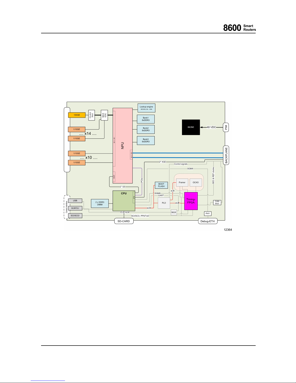
The function of LU1 is to perform layer 2 and layer 3 packet switching, packet forwarding, packet
filtering and traffic management functions. The CPU subsystem is used to control LU1 functionality.
The figure below p resents the LU1 functional block diagram.
Fig. 4 LU1 Block Diagram
2.3.1 CPU Subsystem
The CPU subsystem uses a high performance 64-bit RISC processor with the following memories:
• DDR3 DRAM
• Application FLASH (SD-memory card)
•BootFLASH
The application software is stored in FLASH memory. Thus, it is possible to update the software
on the field when new software feature packs become available. Similarly, the card and interface
parametersarestoredinFLASH,sothosearerestoredafterreset.
8600 Smart Routers 76.8670-40128B
8665 Smart Router FP7.0 Reference Manual © 2015 Coriant.
30
Page 31

2 Line Unit (LU1)
PLD
Various system control functions are embedded in H EP PLD.
I2C
I2C bus and switches are used for accessing devices such as EEPROMs, A/D converters and
temperature sensors.
RTC
The real time clock has backup for short power breaks. The time is kept for at least 20 hours (at
20º C/68º F).
A/D Converter
There is an analog-to-digi tal converter o n the baseboar d. It is used for measuring and monitoring
operating voltages and temperatures.
Asynchronous RS-232 Serial Interface
The asynchronous serial interface is used for local management connections.
External Alarm Interface
There is one dedicated general alarm output. There are also four alarm inputs.
2.3.2 NPU Subsystem
The NPU subsystem performs layer 2 and layer 3 packet switching, p acket forwarding, packet
filtering and traffic managem ent functions. For data buffering and o ther functions, the NPU uses
DDR3 as well as TCAM memories.
2.3.3 FPGA Subsystem
The FPGA subsystem implements the timing l ogi c for the timing block and many miscellaneous
control functions.
2.3.4 Timing Block
The timing block is a Network Element Clock generator with a station clock interface. The
station clock interface supports a [G.703] 2048 kHz synchronization interface or an interface w ith
Synchronization Status M essages.
The 8600 Smart Routers Network Element Clock complies with SEC [G.813] and Stratum 3
generator [GR-1244-CORE]. The functional modelling is specified in [ETS 300 417-6-1] and
[G.781].
76.8670-40128B 8600 Smart Routers
© 2015 Coriant. 8665 Smart Router FP7.0 Reference M anual
31
Page 32
2 Line Unit (LU1)
The timing block has the followin g main functional elements:
• Temperature compensated SEC/Stratum 3+ oscillator with PLL and holdover logic
• Station clock interface with PLL and framer
• Reference clock selection logic
• Clo ck monitoring logic
The Network Element Clock is distributed via the backplane to each line unit where the interfaces
supporting synchronization via Synchronous Ethernet may use it as a Tx reference. In the opposite
direction, the recovered line clock can be transferred to the timing block and, depending on the
configuration, the Network Element Clock is able to use it as a reference. The monitoring logic takes
care that the selected reference clock is valid. It also monitors the operation of both PLL and other
available reference clocks set on the fallback list (contains clock sources/priority order selected by
the user). If a l l the clock sources fail, the Network Element Clock will enter into holdover mode and
maintain the frequency and phase drift within the specified limits.
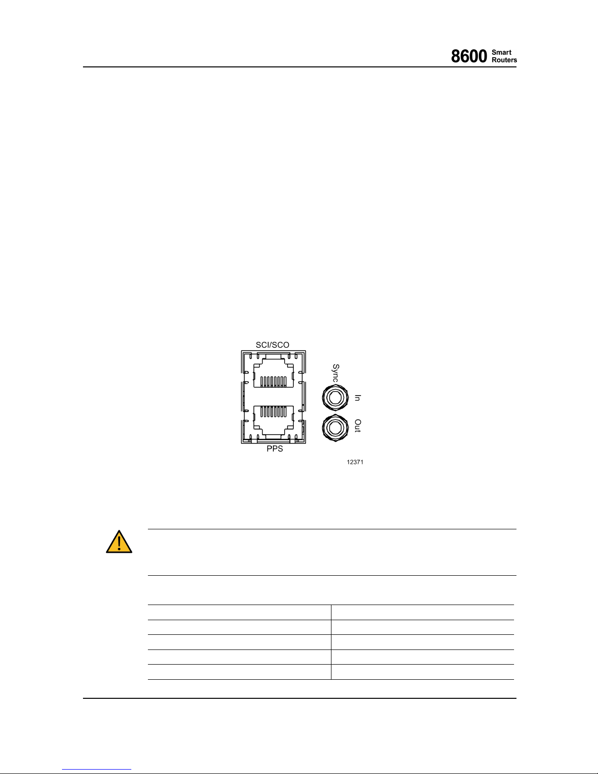
The station clock input/output interface is on the front plate of the timing block. Depending on the
user needs, either coaxial or differential cabling can be used w ith a corresponding connector, i.e.
SMB or RJ-48c. The front panel has also the Time of Day and Pulse Per Second (PPS) interfaces in
an RJ-45 connector. The Time of Day and PPS interfaces use a point-to-point ITU-T V.11 interface.
Fig. 5 8665 Smart Router Timing Front Panel Connectors
The port m ust be connected to the same type of port with proper cable, otherwise network
element functionality may be affected or p hysical damage may occur. Long cables should be
terminated properly to reduce interference.
Station Clock Interface Signals of RJ-48c, Female 8 Pins
Pin #
Description
1
Input A-wire (ring)
2
Input B-wire (tip)
3
Not connected
4
Output A-wire (ring)
8600 Smart Routers 76.8670-40128B
8665 Smart Router FP7.0 Reference Manual © 2015 Coriant.
32
Page 33
2 Line Unit (LU1)
Pin #
Description
5
Output B-wire (tip)
6
Not connected
7
Not connected
8
Not connected
Pulse per Second and Time of Day InterfaceSignalsofRJ-45,Female8Pins
Pin #
Description
1
Pulse per second cable compensation negative,
RS-422 level signal
2
Pulse per second cable compensation positive,
RS-422 level signal
3
Pulse per second negative, RS-422 level signal
4
Ground
5
Ground
6
Pulse per second positive, RS-422 level signal
7
Time of Day negative, RS-422 level signal
8
Time of Day positive, RS-422 level signal
2.3.5 Backplane Data Links
Near End Unit Remote End Unit Remote Device Raw Bandwidth
LU1 SU1
Switch Fabric FPGA 130 Gbp/s with one
operational SU1
200 Gbp/s with two
operational SU1s
LU1 SU1
Control ethernet switch 10 Gbp/s
2.3.6 Power Supply
LU1 contains an integrated power supply (DC/DC converters) on board. It generates all the voltages
needed within different blocks. The input voltage is fed by either of the PIMs (redundancy with
two PIMs). The generated output voltages are galvanically isolated from the battery voltage. LU1
also has polarity protection for input voltages.
2.3.7 Test Features
During boot-up, LU1 performs self tests to verify that the system operational status is nominal.
During norm al operation, the CPU monitors the following:
• LU1 operating voltages
• Temperature inside LU1
76.8670-40128B 8600 Smart Routers
© 2015 Coriant. 8665 Smart Router FP7.0 Reference M anual
33
Page 34
2 Line Unit (LU1)
• Mem ory access (DRAMs, FLASH memories)
• Performance of high speed data links with other cards
LU1 has a watchdog to reset itself in case of a fatal failure in the CPU subsystem.
2.4 Interfaces
LU1 provides two different interface configurations:
• 1x100GBASE-R (CFP2) + 14x1000BASE-X/10GBASE-R (SFP+/SFP)
• 24x100 0BA SE-X/10GBA SE-R (SFP+/SFP)
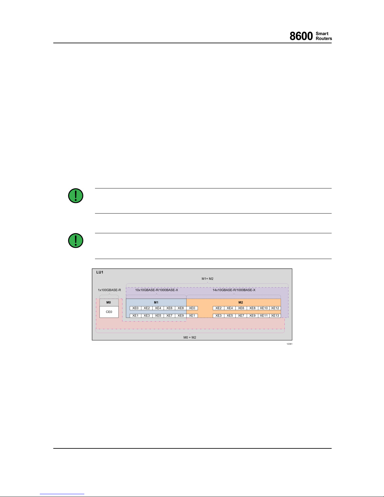
There are three virtual modules M0, M1 and M2 on LU1. The virtual M0 comprises the
1x100GBASE-R interface, M1 comprises the 10x1000BASE-X/10GBASE–R interfaces and M2
comprises the 14x1000BASE-X/10GBASE-R interfaces. M2 is always available, but M0 or M1
cannot be enabled at the same time.
When selecting between the 1G/10G modes it has to be done in pairs, i.e. M1/0 and M1/1,
M1/2 and M1/3 etc.
For M2/4...13 ports the maximum link span with 10GBASE-ZR SFP+ optics is ~65km depending
on the link conditions, all other 10GBASE-R port
s support the full link span.
Fig. 6 LU1 Virtual Modules and Ports
8600 Smart Routers 76.8670-40128B
8665 Smart Router FP7.0 Reference Manual © 2015 Coriant.
34
Page 35
2 Line Unit (LU1)
2.5 Front Panel
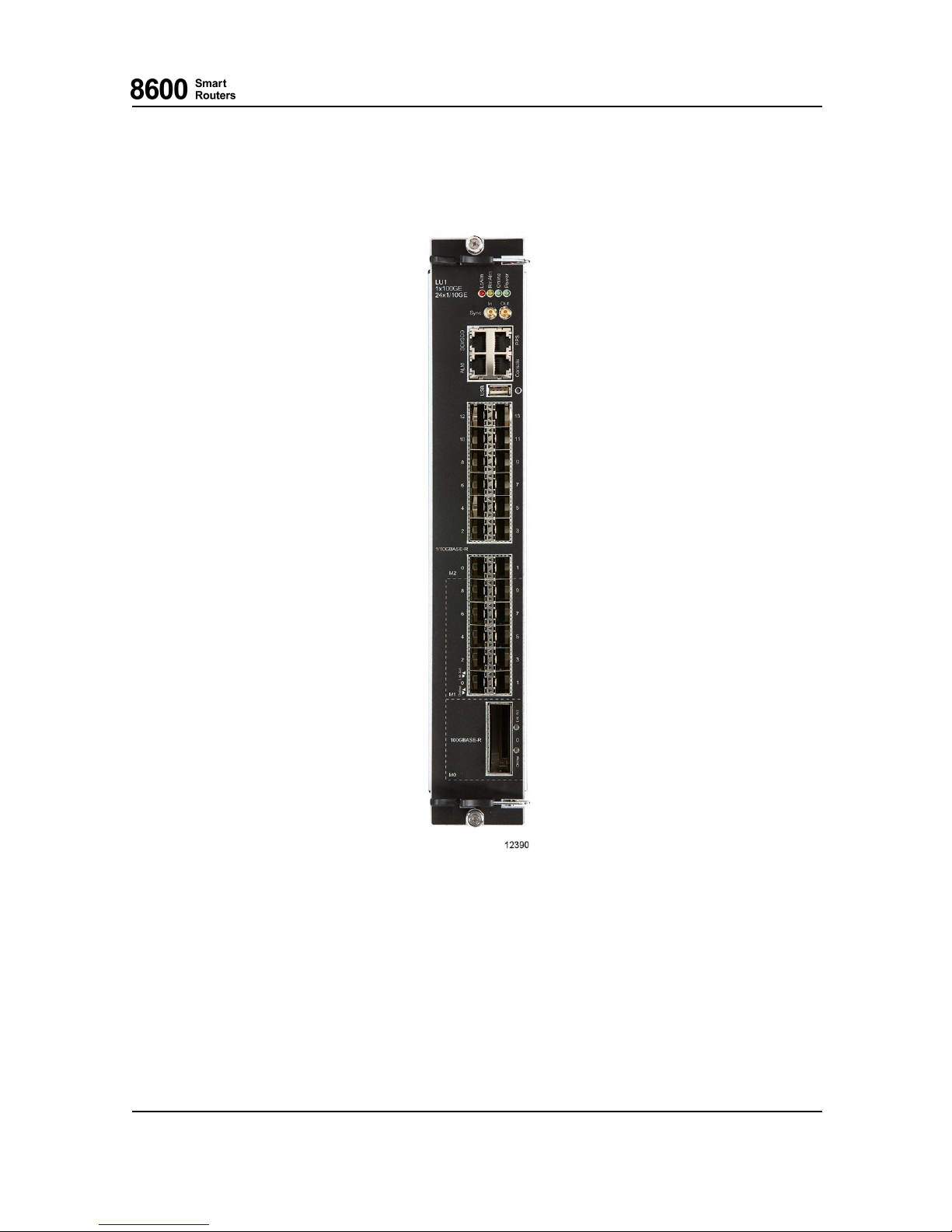
Fig. 7 LU1 Front Panel
2.5.1 CFP2, SFP+ and SFP Transceivers
For more info
rmation on CFP2, SFP+ and SFP transceivers approved by Coriant and the Receive
(Rx) and Transmit (Tx) directions in them, see 8600 S mart Routers Hardware Installation Guide.
76.8670-40128B 8600 Smart Routers
© 2015 Coriant. 8665 Smart Router FP7.0 Reference M anual
35
Page 36
2 Line Unit (LU1)
2.5.2 USB Port
This port is for future use and will become operational in a future software release.
The USB port is not currently supported.
2.5.3 Console Port
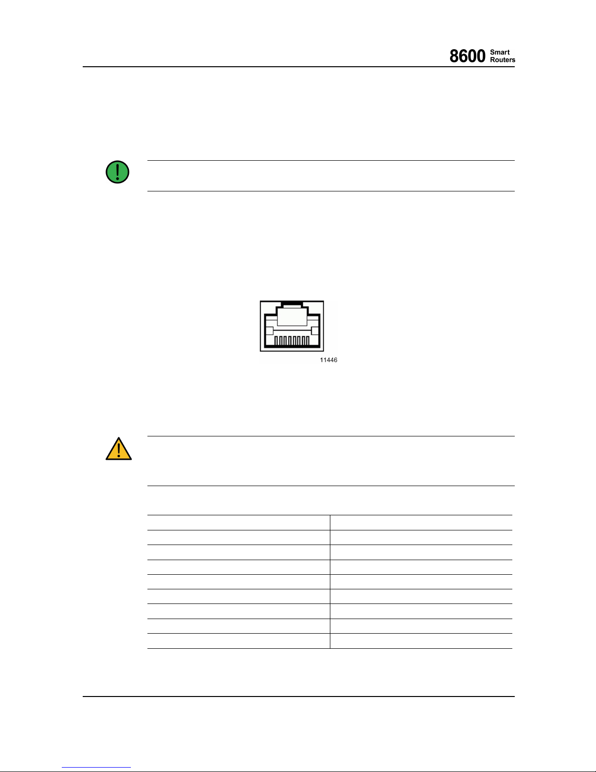
The asynchronous serial interface is accord ing to [EIA/TIA-232-E]. The baud rate
for this interface
is 38400 bps. The connector type is RJ-45, female, with 8 pins.
Fig. 8 RJ-45 Connector
The port m ust be connected to the same type of port with proper cable, otherwise network
element functionality may be affected or p hysical damage may occur. Long cables should be
terminated properly to reduce interference.
RJ-45 Female CLI Connector Pi
nMap
Pin
Signal Name
1
Do not connect
2
Not connected
3
TxD
4 GND
5 Do not connect
6
RxD
7
Not connected
8
Not connected
8600 Smart Routers 76.8670-40128B
8665 Smart Router FP7.0 Reference Manual © 2015 Coriant.
36
Page 37
2 Line Unit (LU1)
2.5.4 External Alarm Interface
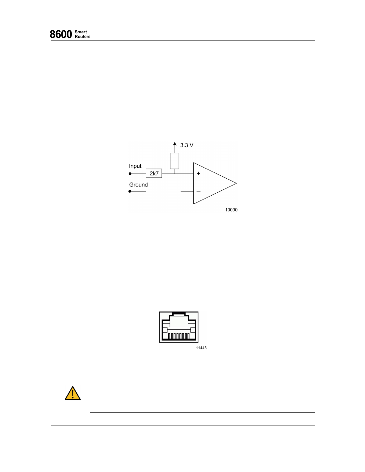
The external alarm interface is used for NE alarms and user configurable output and inputs. It
provides output with solid state relay contacts and inputs for external voltage free contacts, for
example relays. Inputs can also be voltage driven.
The user configurable output is similar to convention al relay and have three pins; common (Com),
normally closed (NC) and normally open (NO) pins. The con figuration is carried throu gh CLI or
8000 I ntel ligent Net wor k Manager.
Fig. 9 Input
In addition to the outputs, there are four user configurable inputs which consist of comparator and
protecting circuits. When the input is connected below the threshold voltage, for example, to ground
by an external device (relay), the state of the input is considered to be closed, otherwise open.
The user is able to configure a possible consequence action if the input state changes, i.e. what
kind of an alarm is risen. A typical application would be, for example, site intrusion detection or
site power supply problems.
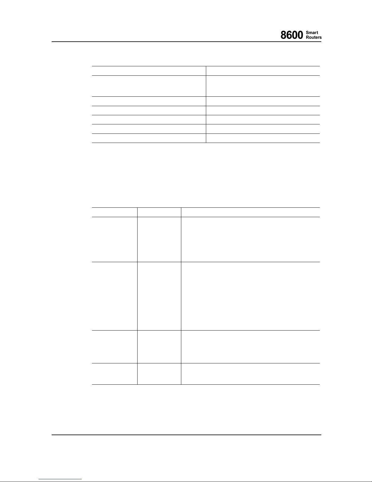
The connector type is RJ-45, female, with 8 pins.
Fig. 10 RJ-45 Connector
The port m ust be connected to the same type of port with proper cable, otherwise network
element functionality may be affected or p hysical damage may occur. Long cables should be
terminated properly to reduce interference.
76.8670-40128B 8600 Smart Routers
© 2015 Coriant. 8665 Smart Router FP7.0 Reference M anual
37
Page 38
2 Line Unit (LU1)
RJ-45 Female Alarm Connector Pin Map
Pin
Signal Name
8
6
7
General Out (NC)
General Out (NO)
General Out (Com)
1 Input1
2 Input2
3 Input3
4 Input4
5
GND
2.6 LU1 LEDs
2.6.1 LU1 Status LEDs
There are fou r LEDs to indicate the LU1 status and one for the power OK status.
LED Name
Color States
Local Alarm
RED
ON when NE itself has a fault.
BLINKING during the following operations:
1) Manually set to forced blinking.
2) If also yellow LED is blinking, the card/NE ha
s reached
shutdown state after " esw -shutdown" command and can be
removed from NE or power can be switched off.
OFF otherwise.
Remote Alarm
YELLOW
ON when online and NE detects or suspects a fault in another
NE or remote site.
BLINKING during the following operations:
1) Boot-up sequence.
2) Inventory create.
3) Inventory (backup) restoration.
4) Manually set to forced blinking.
5) If also red LED is blinking, the card/NE has reached
shutdown state after " esw -shutdown" command and can be
removed from NE or power can be switched off.
OFF otherwise.
OnLine
GREEN
ON when NE is online (it is “up” meaning successful boot-up
sequence finished and startup permission granted). Note that
online NE may still contain errors.
BLINKING when CU is active.
OFF otherwise.
Power
GREEN
ON when NE power is ON and und
ervoltage not detected.
BLINKING Power supply failure.
OFF otherwise.
2.6.2 LU1 Ethernet LEDs
There are two LEDs to indicate the LU1 Ethernet port status.
8600 Smart Routers 76.8670-40128B
8665 Smart Router FP7.0 Reference Manual © 2015 Coriant.
38
Page 39
2 Line Unit (LU1)
LED Name
Color States
Online
GREEN
ON when administrative status for Ethernet interface is online.
BLINKING when manually set to forced blinking.
OFF when administrative status for Ethernet interface is
shutdown or Ethernet link is down.
Link/Activity
GREEN
ON when Ethernet link is up.
BLINKING when Ethernet link is up and there is transmit
or receive activity.
OFF when Ethernet link is down or in shutdown state.
2.7 Cabling
Cabling depends on the SFP, SFP+ or CFP2 type on the optical interfaces, see chapter Pluggable
Transceivers in 8600 Smart Routers Hardware Installation Guide.
2.8 Laser Safety
See more on laser safety in chapter Pluggable Transceivers in 8600 Smart Routers Hardware
Installation Guide.
Laser safety
[IEC60825-1, A1, A2]
[IEC60825-2]
Check that the operational temperature range of the SFP
/SFP+/CFP2 module is suitable for
the installation environment. Note that the temperature of the SFP/SFP+/CFP2 case can be
approximately 15 degrees higher than the ambient temp
erature. For more information on the
allowed SFP/SFP+/CFP2 case temperature range see chapter Pluggable Transceivers in 8600
Smart Ro uters Hardware Installatio n Guide.
2.9 LU1 Cooling
It is important to ensure that adequate cooling is used when an LU1 is installed in a su brack. LU1
has temperature sensors that monitor the unit temperatures during operation. LU1 can endure a
single fan failure but if two or all the fans of one fan module fail, the LU1 located above it will go to
power-save mode after 6 minutes.
Thehightemperaturewarningwillberaisedwhenthecardisoperatedinhighambienttemperature.
This occurs at around +45° C/+113° F ambient. Another reason why this w arn ing can be active is if
the air flow is decreased, which can be caused by a dirty air filter in the subrack. There are also
critical temperature limits which will cause the cards to go to power-save mode if they are exceeded.
All empty line unit slots have to be shielded with blank cover plates.
76.8670-40128B 8600 Smart Routers
© 2015 Coriant. 8665 Smart Router FP7.0 Reference M anual
39
Page 40
3 Switch Unit (SU1)
3 Switch Unit (SU1)
3.1 Overview
SU1 provides 900 Gbps switching capacity for the network element and also control channel
Ethernet switching at 90 Gbps.
As all the other 8600 cards, SU1 is hot-swappable.
In 8665 Smart Router the maximum configuration of two SU1s is supported, but the network
element is fully functional with one SU1.
Each LU1 h as a direct connection via the b ackplane to both switch units in 8665 Smart Router.
Coriant recommend s to use always two SU1s in 8665 Smart Ro
uter.
3.2 Main Features
• CPU subsystem
• SD-card for application software, field upgrade possible
• SwitchmatrixFPGA
• Ethernet control switch
• Operation voltage monitoring and card temperature measurement
• I2C bus for accessing devi
ces such as EEPROMs, A/D converters and temperature sensors
• Serial EEPROM for the factory parameters
3.3 Operation
The function of SU
1 is to perform packet switching between the line units on data and control plane
levels. Control and data plane traffic is separated inside the chassis and they cannot disturb each
other in any situation. The CPU subsystem is used to control the switch unit functionality.
The figure belo
w presents the SU 1 functional block diagram.
8600 Smart Routers 76.8670-40128B
8665 Smart Router FP7.0 Reference Manual © 2015 Coriant.
40
Page 41
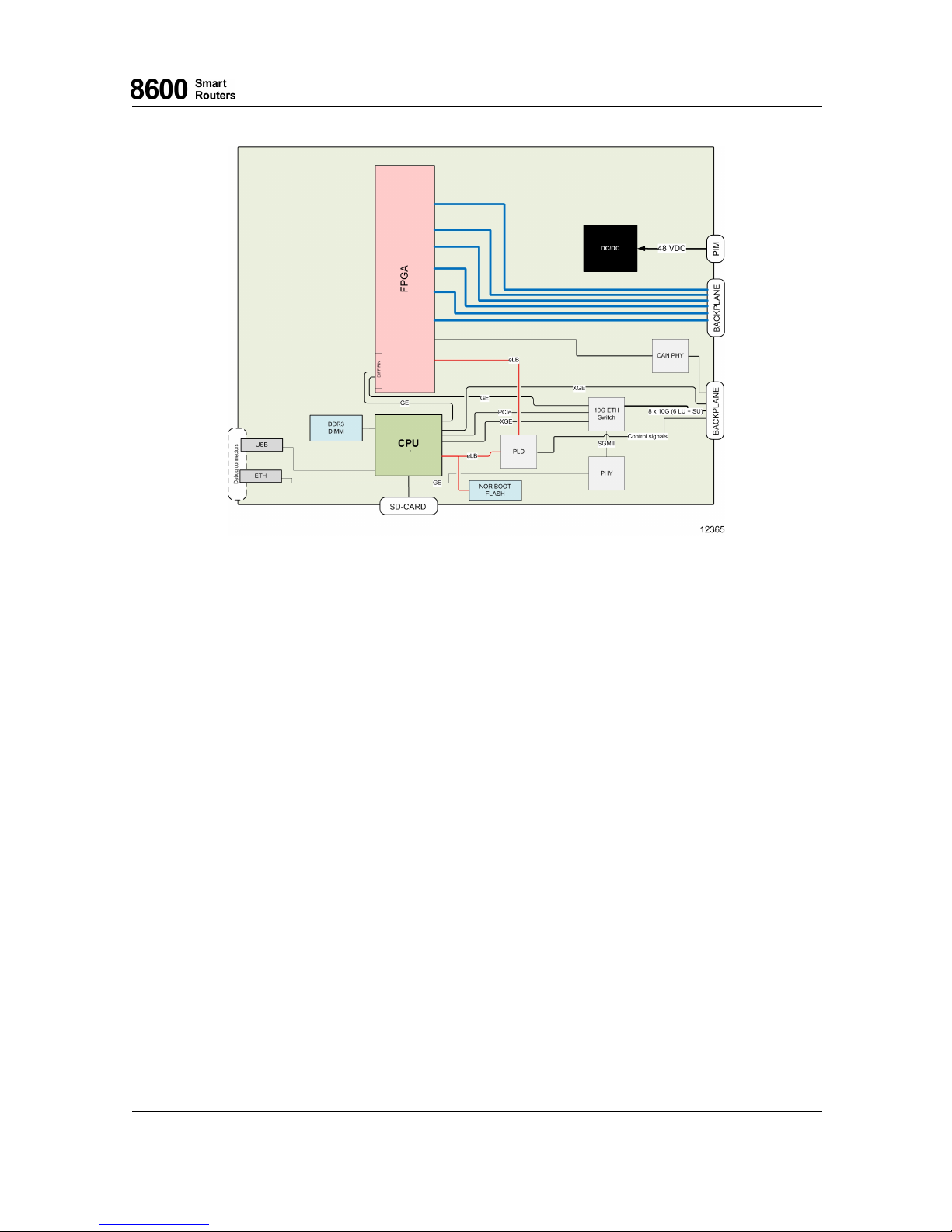
3SwitchUnit(SU1)
Fig. 11 SU1 Block Diagram
3.3.1 CPU Subsystem
The CPU subsystem uses a high perform
ance 64-bit RISC processor with the following memories:
• DDR3 DRAM
• Application FLASH (SD-memory card)
•BootFLASH
The application software is stored in FLASH memory. Thus, it is possible to update the software
on the field when new software feature packs become available. Similarly, the card and interface
parameters are stored in
FLASH, so those are restored after reset.
PLD
Various system control functions are embedded in SUP PLD.
I2C
I2C bus and switches are used for accessing devices such as EEPROMs, A/D converters and
temperature
sensors.
76.8670-40128B 8600 Smart Routers
© 2015 Coriant. 8665 Smart Router FP7.0 Reference M anual
41
Page 42
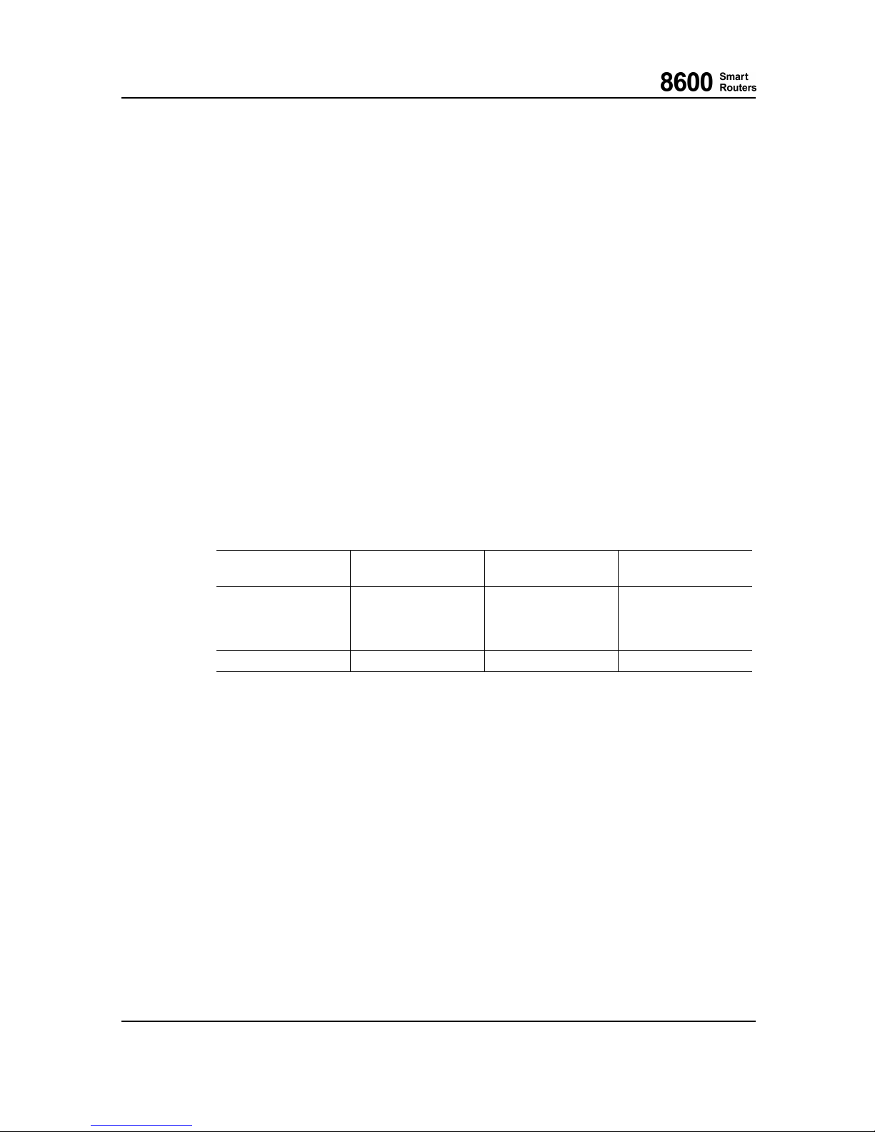
3 Switch Unit (SU1)
RTC
The real time clock has backup for short power breaks. The time is kept for at least 20 hours (at
20º C/68º F).
A/D Converter
There is an analog to digital converter on the baseboard. It is used for measuring and monitoring
operating voltages and temperatures.
3.3.2 FPGA Subsystem
The FPGA subsystem implements t he switch matrix functionality for t he NE at 900 Gbps.
3.3.3 Control Ethernet Switch
The control Ethernet switch is used for NE internal communication and it is fully separated from
the normal data plane.
3.3.4 Backplane Data Links
Near End Unit Remote End Unit Remote Device
Effective
Bandwidth
SU1 LU1
Switch Fabric FPGA 130 Gbp/s with one
operational SU1
200 Gbp/s with two
operational SU1s
SU1 LU1
Control ethernet switch 10 Gbps
3.3.5 Power Supply
SU1 contains an integrated power supply (DC/DC converters) on board. It generates all the voltages
which are needed within diff
erent blocks. The input voltage is fed by either of the PIMs (redundancy
with two PIMs). The generated output voltages are galvanically isolated from the battery voltage.
SU1 has a polarity protection for wrong polarity.
3.3.6 Test Features
During boot-up, SU1 performs self tests to verify that the system operational status is nominal.
During norm al oper
ation, the CPU monitors the following:
• SU1 operating voltages.
• Temperature inside SU1.
8600 Smart Routers 76.8670-40128B
8665 Smart Router FP7.0 Reference Manual © 2015 Coriant.
42
Page 43
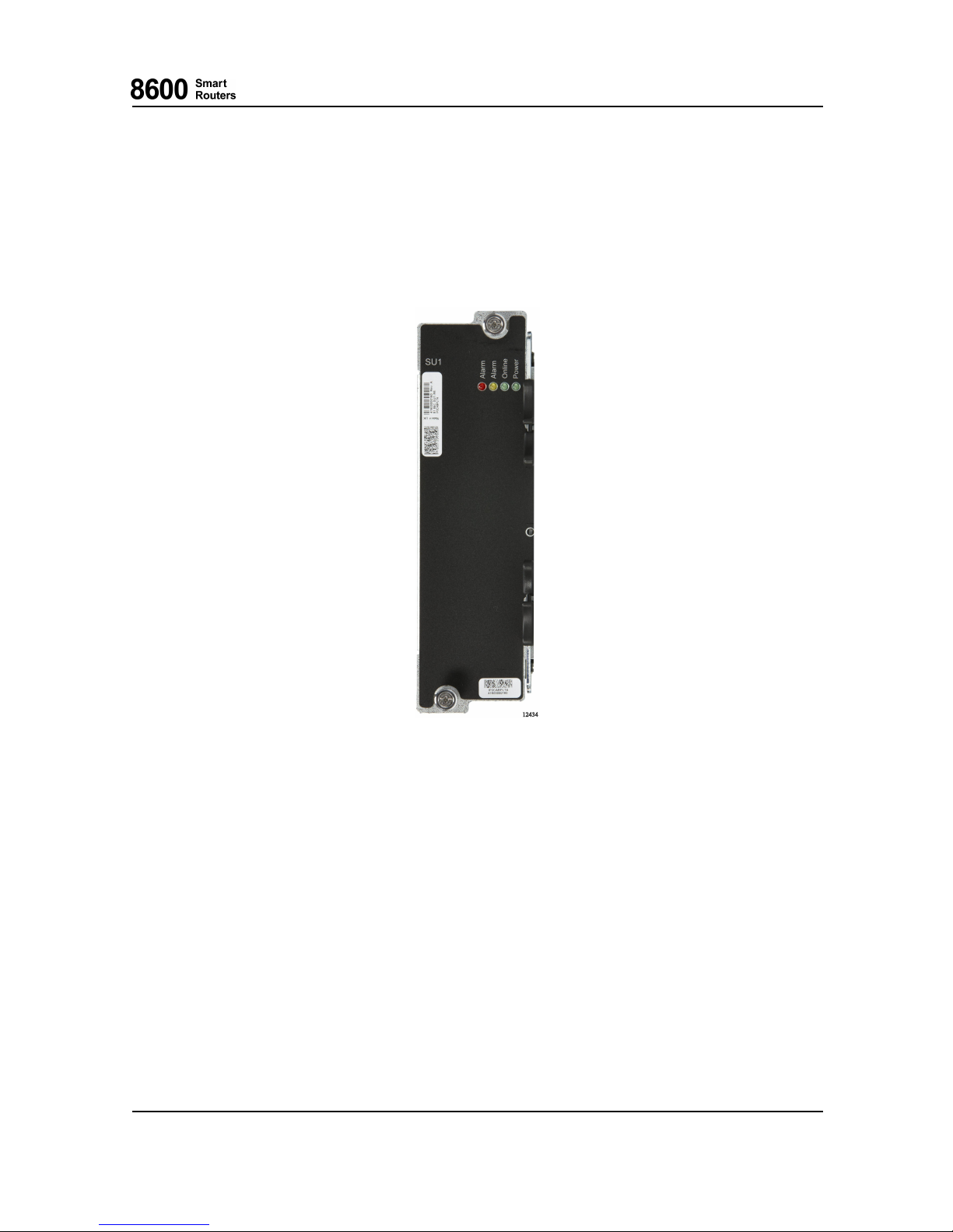
3SwitchUnit(SU1)
• Mem ory access (DRAMs, FLASH memories).
• Performance of high speed data links with other cards.
The SU1 has a watchdog to reset itself in case of a fatal failure in the CPU subsystem.
3.4 Front Panel
Fig. 12 SU1 F ront Panel
3.4.1 SU1 Status LEDs
There are four LEDs to indicate the SU1 status and one for the power OK status.
76.8670-40128B 8600 Smart Routers
© 2015 Coriant. 8665 Smart Router FP7.0 Reference M anual
43
Page 44
3 Switch Unit (SU1)
LED Name
Color States
Alarm
RED
ON when SU1 itself has a fault.
BLINKING during the following operations:
1) Manually set to forced blinking.
2) If also yellow LED is blinking, the card/NE has reached
shutdown state after " esw -shutdown" command and can be
removed from NE or power can be switched off.
OFF otherwise.
Alarm
YELLOW
ON when online and SU1 detects some non-critical fault.
BLINKING during the following operations:
1) Boot-up sequence.
2) Inventory create.
3) Inventory (backup) restoration.
4) Manually set to forced blinking.
5) If also red LED is blinking, the card/NE has reached
shutdown state after " esw -shutdown" command and can be
removed from NE or power can be switched off.
OFF otherwise.
OnLine
GREEN
ON when SU1 is online (it is “up” meaning successful boot-up
sequence finished and and the switch matrix is switching).
Note that online NE may still contain errors.
BLINKING when manually set to forced blinking.
OFF otherwise.
Power
GREEN
ON when NE power is ON and undervoltage not detected.
BLINKING Power supply failure.
OFF otherwise.
8600 Smart Routers 76.8670-40128B
8665 Smart Router FP7.0 Reference Manual © 2015 Coriant.
44
Page 45

4 Power Input Mod ule
4 Power Input Module
4.1 Overview
The DC48 power input module for 8665 Smart R outer offers -48 Vdc supply interface. 8665 Smart
Router subrack provides two power input modules (PIM) on the front side of the NE. Two power
input modules enable redundant power feeding. The nom in al input voltage is -48 Vdc. The -48 Vdc
output of the PIM is routed to the backplane for the use of line units, switch units and fans.
The PIM features are the following:
• Input over-current protection (fuses)
•EMIfiltering
• Input transient overvoltage protection
• Input voltage status monitoring
• Input voltage status LED
• 3,6 V auxiliary Power Supp ly Unit (PSU)
4.2 Operation
The input v oltage is fed through the input fuses and filters to the backplane. The PIM also includes
transient overvoltage protection. Redundancy is realized b y using two PIMs in the NE. There is no
active current sharing between the two PIMs. However, in the case of equal input voltages at input
connectors the current will be divided rather equally between the two PIMs. One PIM is able to
supply the whole current required by the 8665 Smart Router subrack in case of failure in other PIM.
76.8670-40128B 8600 Smart Routers
© 2015 Coriant. 8665 Smart Router FP7.0 Reference M anual
45
Page 46
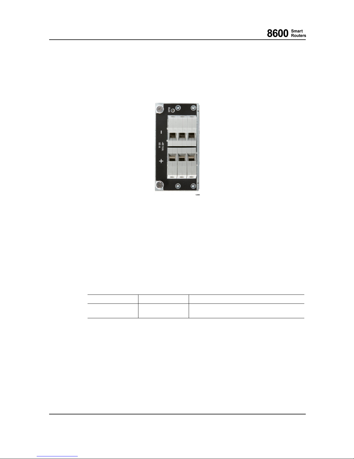
4 Power Input Module
4.3 Front Panel and Connectors
The fo llowing figure show s the PIM front panel.
Fig. 13 8665 Smart Router Power Input Module
The input connector is located on the front side of the PIM. The -48 Vdc output voltage and signal
connector is located on the back side of the PIM.
4.4 Input Fault Detection and LEDS
On the PIM there is a voltage monitor for input voltage detection. If the input voltage after the
fuse is missing or too low, an alarm is forwarded to the CU on the LU1, and a LED indicates the
input voltage status.
LED Name
Color States
Battery Voltage
GREEN
ON when Input voltage is valid.
OFF otherwise.
4.5 Cabling
The PIM can be used with normal copper power cables as screw terminals are used. The maximum
conductor cross section is 25 mm
2
(solid), 16 mm2(stranded) and 16 mm2(with ferrule). The
router can be wired with either single power cable pair or two pairs of cables if thinner cable is
preferred in the installation.
Also a grounding cable with the same or thicker cross-sectional area than the power cable must
be used with the 8665 Smart Router subrack with PIMs installed; that is, at least 16 mm
2
(approximately 5 AWG) or 25 mm2(approximately 3 AWG). For more details on power and
grounding cabling, please refer to 8600 Smart Routers Hardware Installation Guide.
8600 Smart Routers 76.8670-40128B
8665 Smart Router FP7.0 Reference Manual © 2015 Coriant.
46
Page 47

5 Pluggable Transceivers
5 Pluggable Transceivers
For detailed info rmation on the transceivers approved by Coriant supported in 8600 Smart Routers,
refer to 8600 Smart Routers H a rdware Installation Guide.
76.8670-40128B 8600 Smart Routers
© 2015 Coriant. 8665 Smart Router FP7.0 Reference M anual
47
Page 48
6 Technical Specifications
6 Technical Specifications
6.1 8665 Smart Router Technical Specifications
8665 Smart Router subrack
dimensions
445 x 666 x 445 mm (w x h x d), width is without the integrated
side adapter front flange, the width with the integrated side adapter
front flange is 483 mm.
17.51 x 26.22 x 17.51 in (w x h x d), width is without the integrated
side adapter front flange, the width with the integrated side adapter
front flange is 19.01 in.
Standard 19-inch rack or cabinet mounting.
8665 Smart Router subrack
weight
25 kg/55.11 lbs without cards.
34 kg/74.95 lbs with two DC48 Power Input Modules (PIMs) and
three fan modules
Blank cover plate w eight (only
for LU1)
81.86B-LUBLANK-R6 (line unit blank cover with air guide) 0.24
kg/0.52 lbs
Safety compatibility
[EN 60950-1:2006].
[IEC 60950-1:2005].
Electromagnetic compatibility
[EN300 386 V1.6.1]
[FCC 47 CFR Part 15, Subpart B] Class A
Installation environment: telecommunication centre
Storage:
[ETSI EN 300 019-1-1] Class 1.1
Temperature: -5° C to +45° C (+23° F to +113° F).
Transportation:
[ETSI EN 300 019-1-2] Class 2.3
Temperature: -40° C to +70° C (-40° F to +158° F)
2
Climatic/mechanical
compatibility
Operating Conditions:
[ETSI EN 300 019-1-3] Class 3.2
3
Temperature: -5° C to +40° C (+23° F to +104° F).
Relative humidity: 5% to 95%.
Usage altitude 60 m below sea level (106 kPa air pressure) to 3000
m (70 kPa).
The operational temperature range of the whole network element is determined on the
narrowest operating temperature of the interface modules and or SFP/SFP+/XFPs used.
2
Rain is not a llowed.
3
Condensation is not allowed.
8600 Smart Routers 76.8670-40128B
8665 Smart Router FP7.0 Reference Manual © 2015 Coriant.
48
Page 49
6 Technical Specifications
Check that the operational temperature range of the SFP/SFP+/XFP module is suitable for
the installation environment. Note that the temperature of the SFP/SFP+/XFP case will be
approximately 15 degrees higher than ambient temperature. For more information on the
allowed SFP/SFP+/XFP case temperature range see chapter Pluggable Transceivers in 8600
Smart Ro uters Hardware Installatio n Guide.
Power input specification 8665 Smart R outer equipped with PIMs:
• -48 Vdc nominal input voltage
• -40 Vdc...-60 Vdc absolute input voltage range
• 85A maximum current
4
• Fuses inside PIM 2* T60A, strip fuse, bolt down
External circuit breakers shall be used on the battery side of the
power cable for PIM. See recommendations for external circuit
breakers in 8600 Smart Routers Hardware Installation Guide.
Power consumption Maximum power capacity of
• 8665 Smart Router subrack equipped with 8665 Smart
Router DC48 power input modules can be used with power
consumptions of up to 3400 W. With LU-1 and SU-1 the
maximum power that can be used is maximum 1.7kW
The typical and maximum power consumption values for all cards
and modules can be seen in the corresponding chapters of this
manual.
See more information in chapter 1.3 8665 Smart Router Power
Consumption.
Heat dissipation In practice, all electrical power turns into heat in 8600 Smart
Routers. Thus, when calculating the power dissipation of the NE,
the same figure represents the heat dissipation in Watts.
Depending on the configuration of the system the equipment a rea
heat release may exceed the limit specified in [GR-63-CORE]
(995 [W/m2]). If this interferes with the cooling capacity of the
installation facility, additional equipment for room cooling may be
required.
PIM
Powerfeedcardforthechassis.
-48 Vdc power feed.
Max input current: 85 A.
Power feeding protection (redundancy) is achieved with two PIMs
in 8665 Smart Router R2 subrack.
Coriant recommends that 2 PIMs should always be used.
Unit Slots 6 slots for line units, 2 slots for switch units.
4
Chassis equipped with LU1 and SU1 cards does not use the full 85A, but in the worst conditions (temperature, components, voltage) up to 45A.
76.8670-40128B 8600 Smart Routers
© 2015 Coriant. 8665 Smart Router FP7.0 Reference M anual
49
Page 50
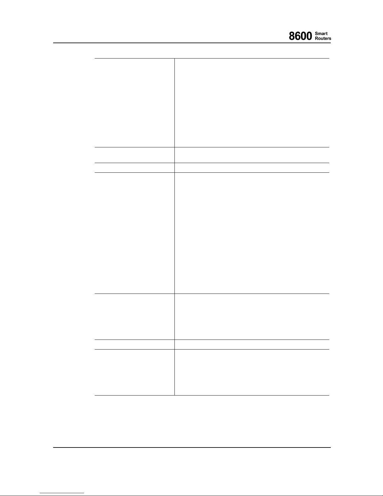
6 Technical Specifications
LU1
1-port 100GE + 24-port 1/10 Gigabit Ethernet Line Unit LU1
(1x100GBASE–R / 24x10GBASE-R/1000BASE-X, note the
different operating modes as all ports are not usable at the same time)
Timing block: ETSI SEC or ANSI Stratum 3 timing reference,
SyncIn/Out (RJ-48c and SMB connectors), PPS (RJ-45 connector,
point-to-point ITU-T V.11 interface), E1, 2MHz, T1 SF, and T1 ESF
interfaces.
Management interfaces: RS-232 serial (RJ-45 connector) and
Ethernet (RJ-45 connector) ports.
External Alarm In/Out interface (RJ-45 connector).
Runs routing and label distribution protocols via the control
functionality (CU).
Unit optionally protected (redundant) - synchronization management
androutingprotocols.
SU1
Switch unit.
Coriant recommends that two SU1s are always used.
Packet buffer size
LU1: 2 GBytes
Performance HW-based architecture guarantees forwarding at wire speed both for
IP and MPLS traffic under any condition.
Throughput:
• 130 Gbp/s bidirectional per LU1 with one operational SU1
• 200 Gbp/s bidirectional per LU1 with two operational SU1s
• 780 Gbp/s bidirectional per subrack assuming simple IMIX LU1
with one operational SU1
• 1200 Gbp/s bidirectional per subrack assuming simple IMIX
LU1 with two operational SU1s
2000 VRFs per LU1 and subrack.
440K IPv4 routes or 440K VPN routes with LU1.
16000 PWE3 tunnels per subrack.
8000 VLANs per LU1.
64 Link Aggregation groups.
16000 ACL entries per LU, 2000 ACL lists per subrack.
2000 Virtual Switching Instances (VSI) with LU1.
500 000 MAC address table with LU1.
IPv4 and MPLS routing and
label distribution protocols and
functionality
Static routing, OSPF-TE [RFC3630], IS-IS-TE [RFC378
4],
(MP)-BGP4 [RFC1771] and [RFC2858], LDP [RFC3036],
RSVP-TE [RFC3209].
IPv4 loadbalancing to RSVP-TE LSPs.
Equal Cost Multi Path (ECMP) routing.
Integrated Routing and Bridging.
IPv4 header compression [RFC2507].
L3 VPN technologies IP VPNs based on [RFC4364].
PWE3 functionality Ethernet raw mode PWE3 [RFC4448].
Ethernet tagged mode PWE3 [RFC4448].
Multi-segment pseudowires [RFC6073].
Pseudowire redundancy [draft-ietf-pwe3-redundancy].
VCCV BFD.
VCCV LSP ping.
Drop counters and history records for Layer 2 pseudowire.
8600 Smart Routers 76.8670-40128B
8665 Smart Router FP7.0 Reference Manual © 2015 Coriant.
50
Page 51
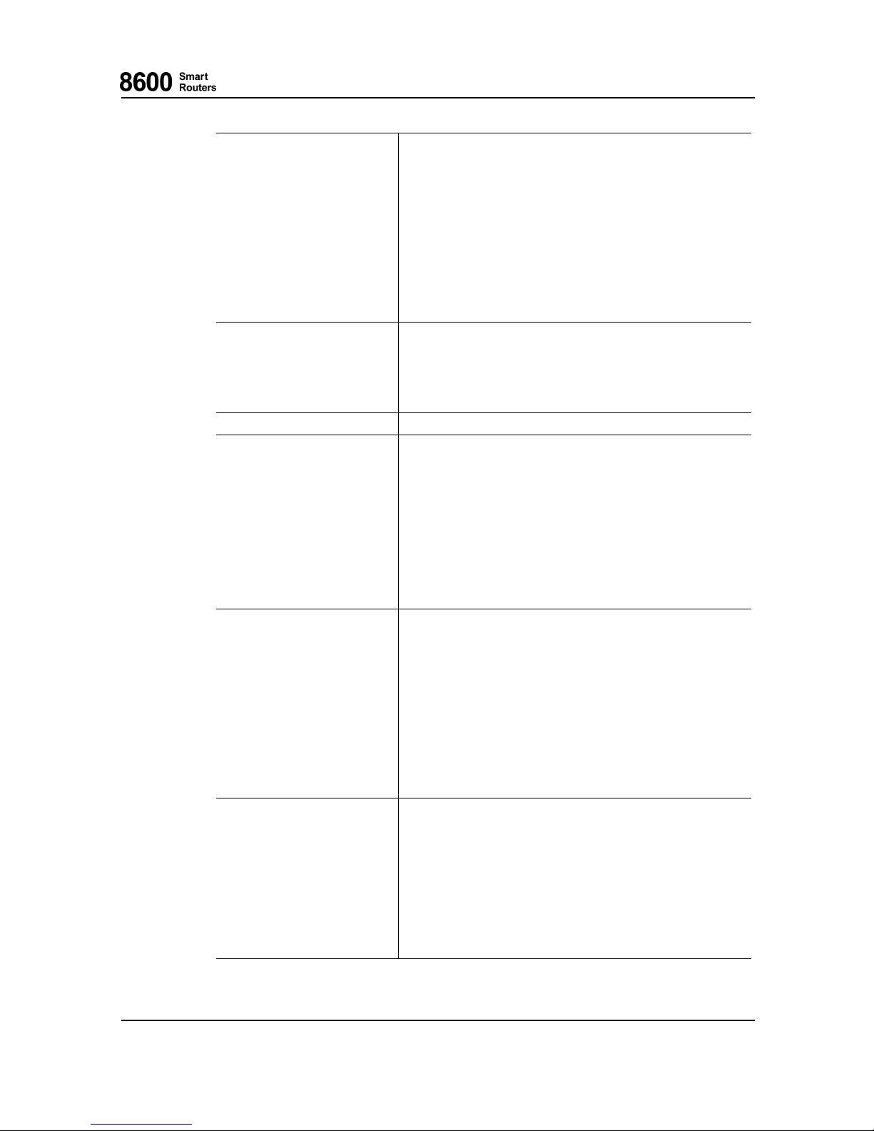
6 Technical Specifications
Ethernet functionality Virtual LAN (VLAN) interfaces.
MAC switching [IEEE802.1D], [IEEE802.1Q].
Virtual Switching Instances (VSI).
[IEEE 802.1ag]/ITU-T [Y.1731] Ethernet OAM connectivity check,
loobpack, and link trace.
ITU-T [Y.1731] Ethernet OAM delay, delay variation, and loss
measurements.
Ethernet line and equipment loops.
[IEEE 802.1AX] Ethernet link aggregation (LAG).
Stacked VLANs (Q-in-Q) in PWE3 applications.
Ethernet over MLPPP in PWE3 applications.
VLAN cross-connections.
VPLS and H-VPLS [RFC4762].
Synchronization
ITU-T [G.8262].
ITU-T [G.813] option 1.
Telcordia [GR-1244] Stratum 3.
Station clock input and output interfaces (SCI/SCO).
Synchronous Ethernet.
[G.8264] SSM over Ethernet.
Link Layer technologies Ethernet, VLAN.
Quality of service functionality DiffServ, DiffServ aware MPLS Traffic Engineering [RFC3270],
[RFC3564] and [RFC5462].
L-LSP and E-LSP supported for MPLS.
7 queues for QoS classes (cs7/StrictPriority1, EF/StrictPriority2, 4
AF classes, Best Effort) per port for IP, MPLS, and Ethernet traffic.
Trafficclassification can be done based on protocol, source and
destination address, source and destination port and Type of Service
field.
Policing with Two Rate Three Color Marker [RFC2698].
Queue based WRED for congestion control, SP/WFQ scheduling.
Optional traffic shaping per traffic class, VLAN or Ethernet port.
VLAN shaping.
Resiliency Common logic 1+1 protection, hot-swappable plug-ins.
1:1 RSVP-TE LSP protection.
Fast Reroute [RFC4090], one-to-one and facility backup modes.
Ethernet Link Protection (ELP).
[IEEE 802.1AX] Ethernet link aggregation (LAG).
Dynamic LSP rerouting.
VRRP [RFC3768].
OSPF Graceful Restart [RFC3623], Graceful Restart mech
anism for
BGP with MPLS [RFC4781] and LDP Graceful Restart [RFC3478]
mechanisms.
Restart signaling for Intermediate System to Intermediate System
(IS-IS) [RFC3847].
Pseudowire redundancy [draft-ietf-pwe3-redundancy].
Connectivity verification IPv4 ping and traceroute.
LSP ping and traceroute for RSVP-TE and LDP LSPs [RFC4379].
Single-hop BFD [RFC5880].
VCCV BFD [RFC 5085].
VCCV LSP ping and traceroute [RFC5085].
MPLS OAM [Y.1711].
Packet Loop Tester (PLT).
[IEEE802.1ag]/ITU-T [Y.1731] Ethernet OAM connectivity check,
loobpack, and link trace.
ITU-T [Y.1731] Ethernet OAM delay, delay variation, and loss
measurements.
76.8670-40128B 8600 Smart Routers
© 2015 Coriant. 8665 Smart Router FP7.0 Reference M anual
51
Page 52
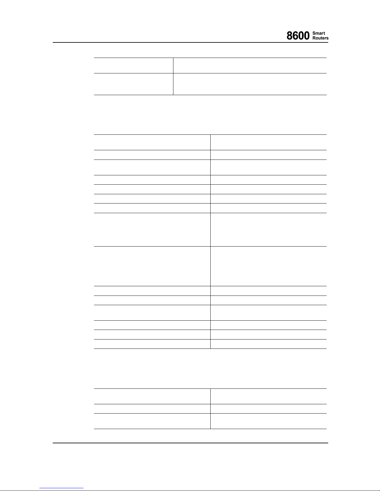
6 Technical Specifications
Management protocols CLI, FTP, SNMP (read), proprietary BMP.
Configuration Change Notifications (CCN).
Other CPU load gauge.
Memory utilization gauge.
NPU usage gauge.
6.2 LU1 Technical Specifi cations
LU1 Technical Specifications
Dimensions 61 x 335 x 387,5 mm (w x h x d)
2.40x13.18x15.25in(wxhxd)
Weight 4.4 kg/9.7 lbs without Pluggable Transceivers
Power consumption Typical 190 W
Maximum 220W
Switch/routing engine
NPU
Packet buffer size
2GBytes
MaxIPv4entries
440 K
Max number of IPv4 VPN entries
440 K
Interfaces — One 100GBASE-R CFP2 interface
— Twenty four 1000BASE-X /10GBASE—R
SFP/SFP+ interfaces.
See chapter Pluggable Transceivers in 8600 S
mart
Routers Hardware Installation Guide.
Synchronization Synchronous Ethernet support at both ingress and
egress:
— Optical egress signal synchronized to ETSI
SEC or ANSI Stratum 3 (NE clock)
— Optical ingress signal used as reference for
Timing Modules on the CUs
MTU
Max. 9500 byte frames
VLANs Max. 4096
MAC filter Erroneous frames; Short and too long frames;
Flow control and overflow
Loopbacks Line loop
Power supply Nominal -48 Vdc
Card LEDs Green, yellow and red
6.3 SU1 Technical Specifi cations
SU1 Technical Specifications
Dimensions 57 x 151 x 388.45 mm (w xhxd)
2.24 x 5.94 x 1
5.29 in (w x h x d)
Weight 3.2 kg/7.05 lbs without Pluggable Transceivers
Power consumption Typical 100 W
Maximum 120W
8600 Smart Routers 76.8670-40128B
8665 Smart Router FP7.0 Reference Manual © 2015 Coriant.
52
Page 53
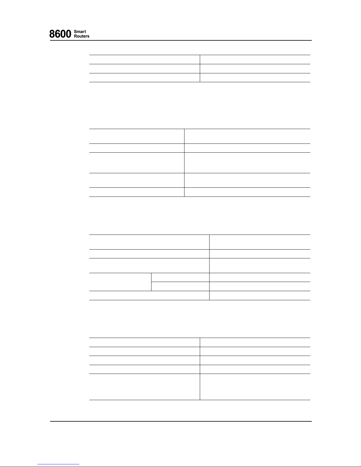
6 Technical Specifications
Switch/routing engine
FPGA
Power supply Nominal -48 Vdc
Card LEDs Green, yellow and red
6.4 8665 Smart Router DC48 Power Input Module Technical
Specifications
DC48 Power Input Module (PIM) for 8665 Smart Router Technical Specifications
Dimensions 45.75 x 112 x 385.75 mm (w x h x d)
1.80x4.40x15.18in(wxhxd)
Weight 1.4 kg/3.08 lbs
Input specifications -48 Vdc nominal input voltage (-40 ... —60VDC)
85 A input current
3400 W maximum power (for the whole NE)
Power consumption Typical 35 W
Maximum 62.5 W
Alarms Battery voltage monitoring
6.5 8665 Smart Router Fan Module Technical Specifications
8665 Smart Router Fan Module Technical Specifications
Dimensions 143x59x375mm(wxhxd)
5.62 x 2.32 x 14.76 in (w x h x d)
Weight 2.2 kg/4.85 lbs
Power consumption Typical 50 W
Max. 100 W
single fan failure Less than 72 hoursTime to change fan module
more than one fan failure Within three hours, or at least within one day
Air filter change At least twice a year
6.6 Timin g Block Technical Specifications
Technical Specifi
cations of SEC [G.813] and Stratum 3 [GR-1244-CORE]
Frequency accuracy in free-running condition
± 4.6 ppm
Minimum pull-
in range
± 4.6 ppm
Maximum pull-out range
± 20 ppm
Wander in locked mode < 40 ns ( t < 1 s )
Noise transfer Bandwidth is between 1 … 10 Hz when the clock
system
operates in SEC mode and < 0.1 H z when
it operates in Stratum 3 mode,
phase
gain < 0.1 dB
76.8670-40128B 8600 Smart Routers
© 2015 Coriant. 8665 Smart Router FP7.0 Reference M anual
53
Page 54
6 Technical Specifications
Short-term phase transient response < 120 ns over any period S up to 16 ms
Holdover performance in constant temperature Initial frequency offset: < 0.05 ppm
Ageing : < 0.01 ppm/day
Technical Specifications o f Station Clock Interface
Frequency or data rate 2048 kHz or 1544 kHz ± 4.6 ppm
Electrical characteristics According to [G.703] or ANSI [T1.102]
Nominal impedance 75 Ω unbalanced, 100 Ω or 120 Ω balanced
Maximum jitter at an output port
0.05 UI peak-to-peak, measured within the
frequency range 20 Hz to 100 kHz
Attenuation margin 0 to 6 dB
Loss of input clock signal detection According to [G.775], short haul operation -12 to
-15 dB
Input return loss 100 kHz to 3100 kHz ≥ 18 dB
Output return loss According to [ETS 300 166]
Connector type
SMB (50-ohm unbalanced male)
RJ-48c (balanced female)
RJ-45 (time of day)
8600 Smart Routers 76.8670-40128B
8665 Smart Router FP7.0 Reference Manual © 2015 Coriant.
54
Page 55
End of Life Treatment
End of Life Treatment
Disposal of electrical and electronic waste in member states of the European Union shall be done
according to Directive 2002/96/EC Waste of Electrical and Electronic Equipment (WEEE) and
local legislation.
Do not dispose electrical and electronic equipment with unsorted municipal and household waste.
Please consult yo ur local authorities for suitable disposal method for electronic and electrical waste.
Correct handling of the disposed equipment contributes to reuse, recycling and other form of
recovery to protect the environment.
The equipment is marked with the figure shown below, to indicate that the equipment must be
collected separately.
76.8670-40128B 8600 Smart Routers
© 2015 Coriant. 8665 Smart Router FP7.0 Reference M anual
55
 Loading...