

Page 1

Motor Coach Trip Computer
Operator’s Manual
MODEL 2510-X
Page 2

Trademarks Coretronics is a registered trademark, and TripTek is a
trademark of Coretronics, Inc.
Coretronics, Inc.
1251 E. Iron Eagle Drive
Eagle, ID 83616
Telephone: (208) 938-6331
Fax: (208) 938-6334
www.triptek.net
Patented
Page 3

Table of Contents
Quick Reference ……………………………………………….….……..…1
Overview ……………………………….….……………………….………..2
Description ……………………………….………………………..………..2
Display …………………………………….……………………….…….….2
Keypad Keys …………………………………………….……….………...3
Second Level …………………………………………………….……...….3
Clock Battery …………………………………………………….………...3
Operating the TripTek Computer …………………………….………….4
Check List Screen …………………………………………….……...........4
Today Screen ………………………………………………….……….......5
Leg Screen …………………………………………………….……...........6
Trip Screen …………………………………………………….…………..6
Coach Data Screen …………………………………………….….………7
Maintenance, Setup & Adjustment Screens ………………….………....8
Maintenance Screen ……………….………………………….………......8
Setup Menu Screen …………………………………………….…………9
Compass Zone Adjustment Screen …………………………….…..........9
Compass Calibration ………………………………….…………….......10
Maintenance Setup Screens ………………………….…………………11
Set Clock Screen …………………………………….………..……........11
Coach MPG ON/OFF Screen ……………………….…………………..12
Customer Service Screen …………………………….………………….12
Page 4

Quick Reference
Series 2510
07/24/04
Oil Can:
If an oil can is displayed on any screen or “Engine Maintenance” is blinking on the CHECK LIST a
maintenance item needs attention. Refer to information on “MAINTENANCE” screen in this manual.
Maintenance/Setup/Information screens:
To get access to these screens press up and down keys simultaneously. (Ref this manual)
Maintenance Data:
Miles or hours have been preset at the factory to satisfy engine, transmission and generator break in
periods. Check MAINTENANCE SETUP screen to verify accurate breakin period.
After break in period reset mile and hour intervals to an appropriate setting to match your preferred
cycle.
If miles and/or hours are being set in mid cycle, set interval to accommodate remainder of cycle. After
maintenance cycle, change mile and/or hour intervals to full cycle period.
MPG Average:
To activate MPG Average on the COACH screen refer to the COACH MPG ON/OFF screen under
SETUP MENU. Reference Maintenance, Setup and Adjustment Screens section in manual.
Page 1
Page 5

Operator’s Manual
Series 2510
06/01/04
Overview
TripTek is a trip and coach management computer designed for motorhomes. By receiving data from multiple
sources, i.e. electronic engine computer, compass and temperature sensors (optional), and other sources, the
system collects, analyzes, and saves data in memory and then displays information on the rear vision monitor.
Description
TripTek is comprised of multiple parts: a keypad, computer (behind dash), compass and temperature sensors
(optional), and utilization of the rear vision monitor for display.
Display
When the ignition is turned on, a pre-trip CHECK LIST is displayed to guide the operator through a list of
items to verify readiness of coach for travel.
To make efficient use of the data collected, and to best serve an actual vehicle trip, the system offers the
operator four separate travel screens: TODAY, LEG, TRIP, and COACH. Time, Day, Date and Year are also
included on these screens.
The TODAY screen is designed to give daily information. It provides miles to scheduled destination, time to
destination, miles traveled, time traveled, average MPG and average MPH. As an option, it will also give you
both inside and outside coach temperature and compass heading.
The LEG screen is designed to give information from fill to fill or for a trip. It provides average MPH, time
traveled, miles traveled, gallons used (by engine), average MPG, road speed, and cruise control status and
compass heading.
The TRIP screen is designed for long term data tracking for a complete trip or longer. It provides average
MPH, hours traveled, miles traveled, gallons used (by engine), average MPG and current MPG and compass
heading.
The COACH screen is designed to give you both coach and engine/transmission performance and operational
data. It provides gears select & monitor, turbo boost, engine temperature, transmission temperature, oil
pressure, average MPG and oil temperature and compass heading.
Note: If referenced information is not shown on one of these screens, that information is not offered or currently
being received from engine or transmission.
On a second level of screens there will be MAINTENANCE, SETUP MENU (COMPASS ZONE
ADJUSTMENT, COMPASS CALIBRATION, MAINTENANCE SETUP, SET CLOCK SCREEN, COACH
MPG ON/OFF), CUSTOMER SERVICE and VERSION INFORMATION.
The MAINTENANCE screen displays when to change engine oil, eng. fuel filter, transmission oil, generator oil
and gen. fuel filter. If Oil Can is displayed on travel screens a maintenance item needs attention. Line item will
be blinking.
The COMPASS ZONE ADJUSTMENT screen is used to maintain compass accuracy by state. To achieve
maximum accuracy, it is recommended to change the zone setting when traveling from state to state.
The COMPASS CALIBRATION screen is for calibration of the compass after its initial installation or anytime
the compass sensor is replaced or relocated.
The MAINTENANCE SETUP screen is to set the interval (miles for engine and hours for generator) for
maintenance.
Page 2
Page 6

The SET CLOCK screen is to set all parameters of the clock, i.e. time zone, daylight savings, month, day,
year, time, am/pm and format (small, large or off).
The COACH MPG ON/OFF screen is to give the operator a way of turning MPG Average (COACH screen) on or
off.
The CUSTOMER SERVICE screen is to give the operator easy access to the phone numbers and web page
of the coach manufacturer.
Keypad Keys
(Maintain rear vision monitor in “on” position to display trip data)
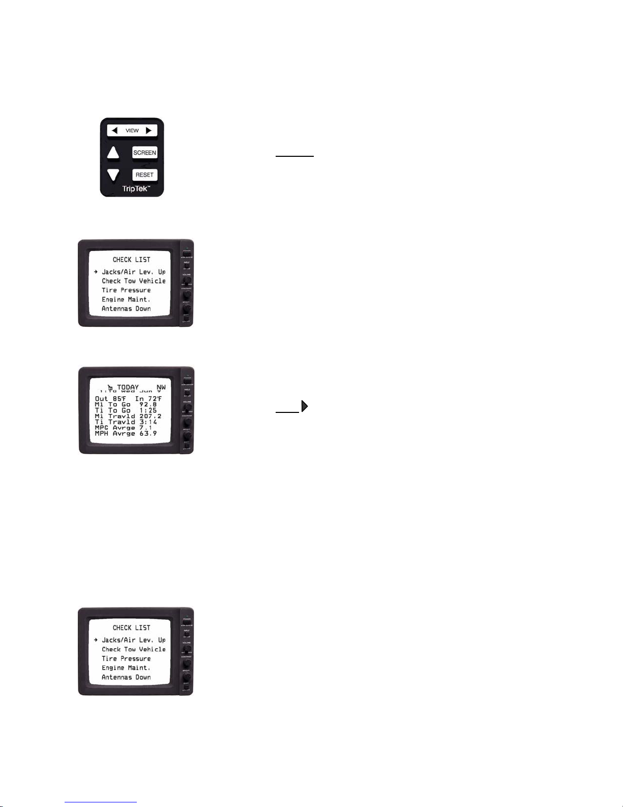
Use the up ___ and down ___ keys to step through each line item of the CHECK LIST.
Use the VIEW key to move out of the CHECK LIST screen and go to the travel screens.
The VIEW key displays the four travel screens: TODAY, LEG, TRIP, and COACH. By pressing this key,
with the monitor on, the computer will sequence through the four data screens and one blank screen. The
system is also designed to sequence forward or backward, depending on which side of the key is pressed.
The SCREEN key will change data/picture contrast by changing the text background.
Successive presses to the VIEW or SCREEN keys will give the following options:
Data on picture: The ability to view a data screen and still see the rear vision image.
Data only: View data screen only with either a dark or light background for great contrast.
Picture only: View rear vision image only.
The RESET key will zero all or part of the data on the currently viewed screen.
The up ___ and down ___ keys set miles to be traveled today. Holding down a key will scroll through
numbers. This is operational only on the TODAY screen.
To get the second level SCREEN SELECTION screen, push the up___ and down ___ keys simultaneously.
SECOND LEVEL
Use the up ___ or down ___ key to change selection.
Use RESET key to select screen.
Use VIEW
key to return to TODAY screen (or as noted).
Clock Battery
The TripTek computer utilizes a replaceable battery # CR1632 to retain its clocks memory when the system
is off.
Battery replacement:
1. Disconnect TripTek computer from coach. Most connectors utilize a latch to retain their position.
Compress latch arm to remove connectors.
2. With the removal of four screws from the two long sides of the computer lift off the back cover and
expose the inside of the system.
3. Locate battery on back surface of computer
4. Slide battery out from under metal spring clip.
5. Replace with positive side (+) of battery facing up.
6. Reverse steps 1 through 4 to reassemble system.
Page 3
Page 7
Operating the TripTek Computer
Model 2510X
6/01/04
Turn the ignition switch ON.
Turn the rear vision monitor ON. Display rear vision picture.
Press the SCREEN
the picture.
Note: If vehicle is put into reverse, the rear vision system will override the
computer and clear TripTek data from the screen until transmission is
taken out of reverse.
With the above steps completed, the “CHECK LIST” screen will be displayed
on the backup monitor.
There will be multiple screens displaying checklist items.
“CHECK LIST” will only come up when ignition is first turned on.
key on the keypad to change contrast of displayed data to
Press the VIEW key on the keypad. The “TODAY” screen will display on
the backup monitor.
Check List Screen
The CHECK LIST screen is designed to give you a list of items to verify readiness of coach for travel.
This screen will give you a list of items to check off to insure readiness of coach
for travel.
If a line item is blinking (i.e. “Engine Maint.”), it would imply that service is
required.
Page 4
Page 8
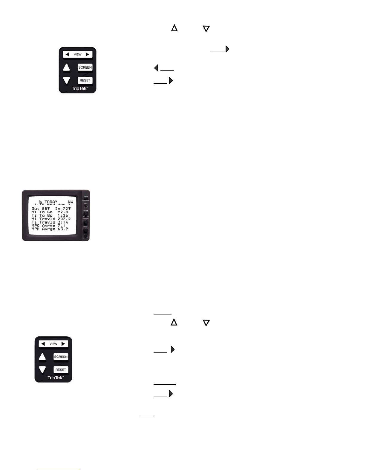
Using the up ___ and down ___ keys will let you step down each line item and
check them off as you verify completion of task.
If a line item is blinking, press VIEW
“MAINTENANCE”) to evaluate the problem.
Press VIEW
Press VIEW key to move out of “CHECK LIST” and into “TODAY” screen.
Will function only on non-blinking lines.
The “CHECK LIST” is only visible when ignition is first turned on.
key again to return to “CHECK LIST”.
to move to the appropriate screen (i.e.
Today Screen
The TODAY screen is designed to give you daily information.
NW:
Oil Can: If Oil Can is displayed a maintenance item needs attention
Time/Date: Time, Day, Date and Year. Line can be configured to large
Out/In Temp: Outside and inside coach temperature (optional).
Miles To Go: Remainder of user entered miles to scheduled destination.
Time To Go: Approximate time to scheduled destination, utilizing “Miles To
Mi Traveled: Miles traveled since “TODAY” screen reset.
Time Traveled: Time traveled since “TODAY” screen reset.
MPG Average: Average miles per gallon since “TODAY” screen reset.
MPH Average: Average miles per hour since “TODAY” screen reset.
Press RESET
Using the up ___ and down ___ keys, set the miles you will travel today. The longer the
key is held down, the faster the number will scroll. Miles can be changed throughout the
day.
Press VIEW
Note: As “Miles Travld” changes, “Miles To Go” and “Time To Go” will also change
Press SCREEN
Press VIEW
Note: To move forward or backward through the screens, press the side of the
VIEW
and follow screen instructions to zero out “TODAY” screen.
to return to “TODAY” screen.
accordingly.
to change data/picture contrast.
to move to the “LEG” screen.
key that displays chosen direction.
Page 5
Compass Heading (optional)
(Ref. “MAINTENANCE” screen).
text (default as pictured), small or off.
Go” and current speed.
Page 9
The TRIP screen is designed for long term data tracking for a complete trip or longer.
Leg Screen
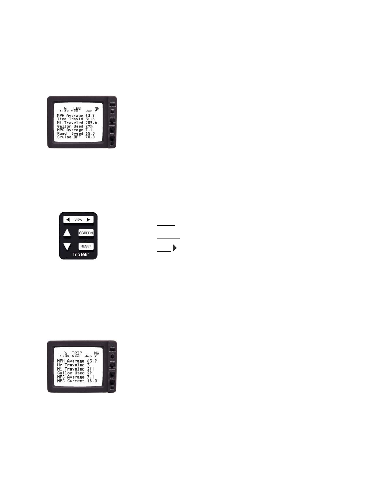
The LEG screen is designed to give you information from fill to fill.
NW: Compass heading (optional)
Oil Can: If Oil Can is displayed a maintenance item needs
attention (Ref. “MAINTENANCE” screen)
MPH Average: Average miles per hour since “LEG” screen reset.
Time Traveled: Time traveled since “LEG” screen reset.
Mi Traveled: Miles traveled since “LEG” screen reset.
Gallons Used: Gallons of fuel utilized by engine from the time of
“LEG” screen reset. Data from engine computer.
MPG Average: Average miles per gallon since “LEG” screen reset.
Road Speed: Current coach speed.
Cruise OFF: Status of cruise control and its set speed. Displays
preset speed while cruise is off and actual speed
while cruise is on.
Press RESET
Press SCREEN to change data/picture contrast.
Press VIEW
and follow screen instructions to zero out “LEG” screen.
to move to the “TRIP” screen.
Trip Screen
NW: Compass heading (optional)
Oil Can: If Oil Can is displayed a maintenance item needs
MPH Average: Average miles per hour since “TRIP” screen reset.
Hrs Traveled: Hours traveled since “TRIP” screen reset.
Mi Traveled: Miles traveled from time of “TRIP” screen reset.
Gallons Used: Gallons of fuel utilized by engine from time of
MPG Average: Average miles per gallon since “TRIP” screen reset.
MPG Current: Instantaneous miles per gallon.
Page 6
attention (Ref. “MAINTENANCE” screen).
“TRIP” screen reset. Data from engine computer.
Page 10
Press RESET
Press SCREEN to change data/picture contrast.
Press VIEW
and follow screen instructions to zero out “TRIP” screen.
to move to the “COACH” screen.
Coach Screen
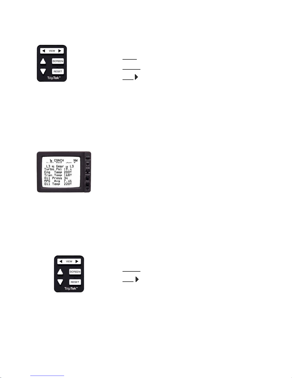
The COACH screen is for coach and engine performance.
NW: Compass heading (optional)
Oil Can: If Oil Can is displayed a maintenance item needs
Gear: Transmission gears selected and attained.
N=Neutral, C=Converter, L=Converter Lock
Turbo PSI: Turbocharger boost pressure.
Eng Temp: Engine coolant temperature.
Tran Temp: Transmission oil temperature.
Oil Pres: Engine Oil Pressure.
MPG Average: Average miles per gallon for life of coach.
Oil Temp: Engine oil temperature.
Note: If referenced information is not shown on your “COACH” screen, that
information is not offered from engine or transmission.
Note: MPG Average can be turned ON or OFF in the next level of screens, ref.
Maintenance, Setup and Adjustment Screens.
Press SCREEN to change data/picture contrast.
Press VIEW
to move to the “BLANK” screen.
Page 7
attention (Ref. “MAINTENANCE” screen)
Page 11
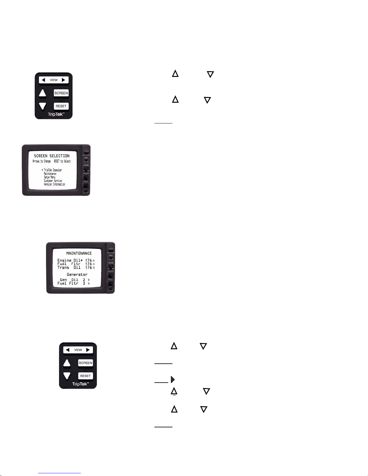
Maintenance, Setup and Adjustment Screens
Press the up ___ and down ___ keys simultaneously to get the second level
screens (“SCREEN SELECTION”).
Using the up ___ and down ___ keys will let you step through each line item to choose
the appropriate screen.
Press RESET
TripTek Computer: Return to travel screens.
Maintenance: Maintenance screen.
Setup Menu: All setup screens.
Customer Service: Coach customer service screen.
Version Info: Product version information.
key to display screen.
Maintenance Screen
The MAINTENANCE screen displays when to change oil and filters.
Engine Oil: Miles since last oil change.
Fuel Fltr: Miles since last fuel filter change.
Trans Oil: Miles since last transmission oil change.
Gen Oil: Hours since last generator oil change.
Fuel Fltr: Hours since last generator fuel filter change.
Note: To change line item duration refer to “MAINT. SETUP” screen.
Note: If Oil Can is displayed on top level screens the maintenance line item that
is blinking needs attention.
Press the up ___ or down ___ key to select the line item desired.
Press RESET
filter change.
Press VIEW
Press the up ___ and down ___ keys simultaneously to return to the “SCREEN
SELECTION” screen.
Press the up ___ or down ___ key to select the “SETUP MENU” screen.
Press RESET
and follow screen instructions to zero out line item after oil or
key to return to “TODAY” screen.
key to display screen.
Page 8
Page 12
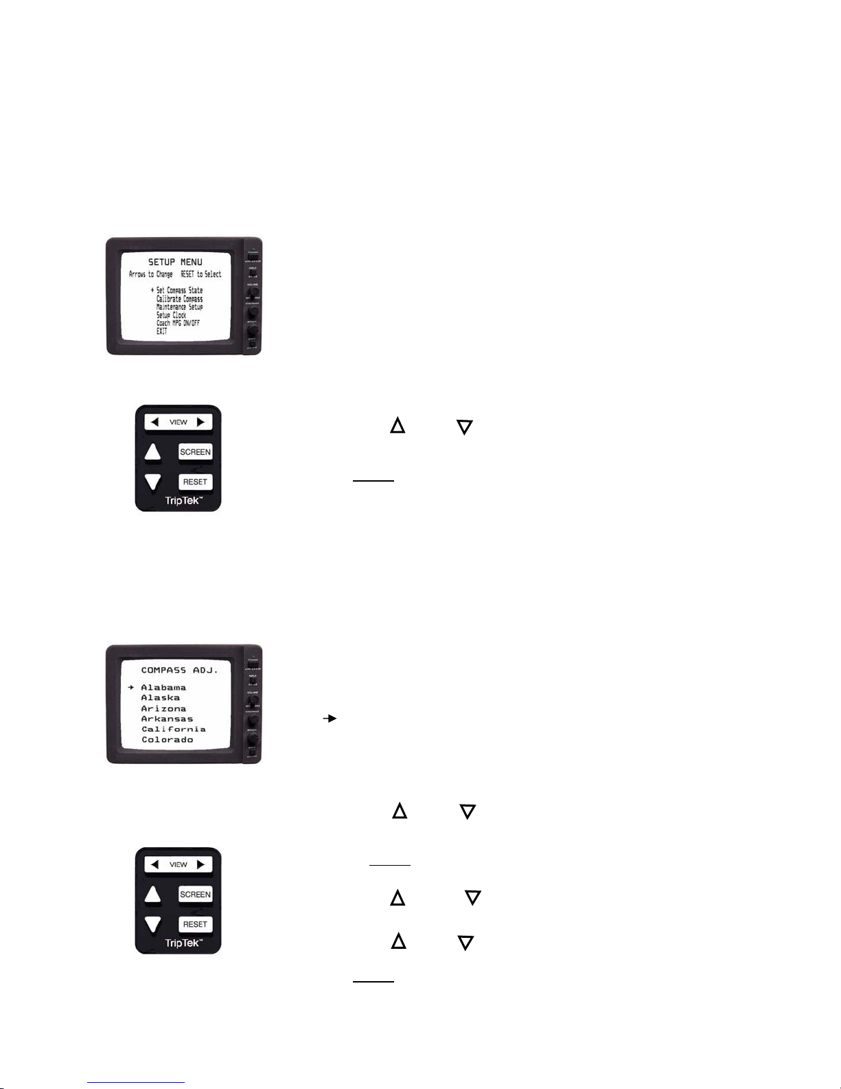
Setup Menu Screen
The SETUP MENU screen will display all setup screens.
Set Compass State: Set compass zone by state.
Compass Calibration: Compass calibration procedure.
Maintenance Setup: Setup maintenance parameters.
Setup Clock: Clock setup screen.
Coach MPG ON/OFF: Turn on or off MPG average on coach screen.
EXIT: Exit setup menu screen.
Press the up ___ or down ___ key to step through each line item to choose the
appropriate screen.
Press RESET
key to display screen.
The SET COMPASS STATE screen is to maintain compass accuracy by state.
Compass Zone Adjustment Screen
STATES: Alphabetical listing of all states to easily set zones to
maximize compass accuracy.
: Pointer to current location of coach.
Using the up ___ or down ___ key will let you scroll through the list of states to
pick the state of your current location.
Pressing RESET
“TODAY” screen.
Press the up ___ and down ___ keys simultaneously to return to the “SCREEN
SELECTION” screen.
Press the up ___ or down ___ key to select the “SETUP MENU” screen.
Press RESET
will change the zone to the chosen state and return to
key to display screen.
Page 9
Page 13
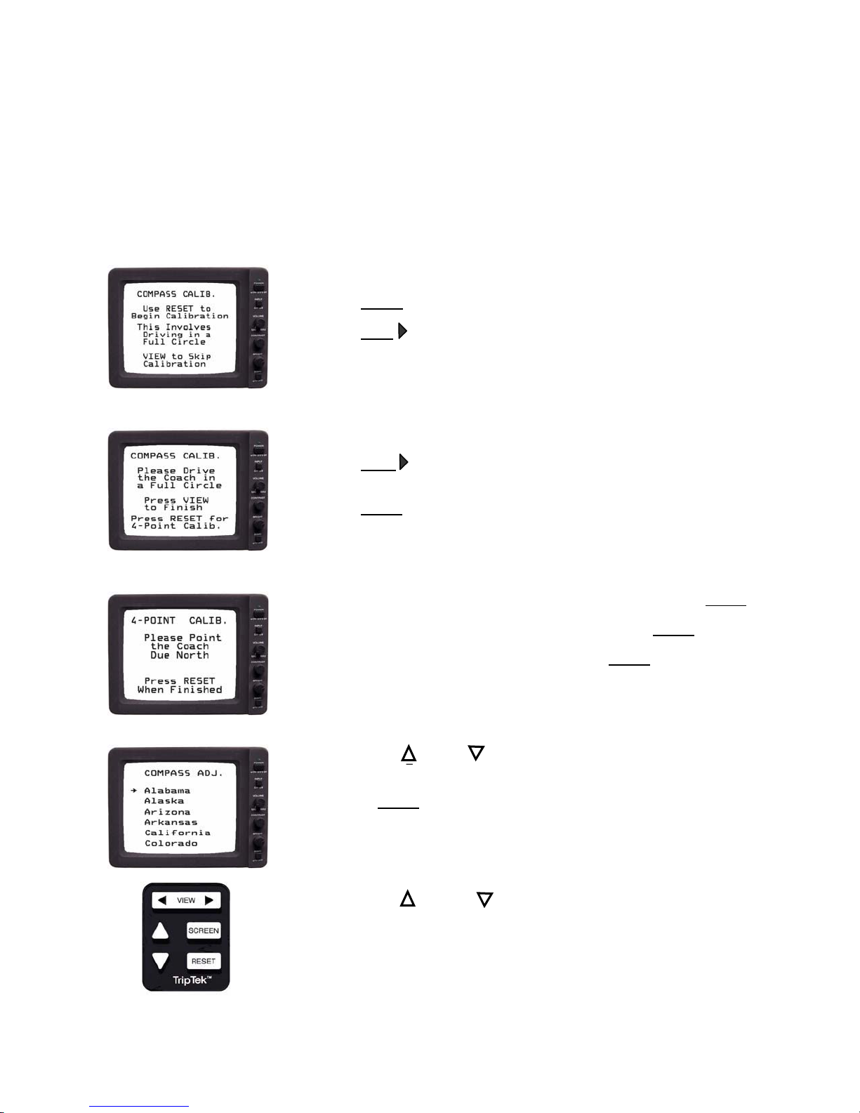
Compass Calibration
The compass must be calibrated after its initial installation or at anytime it is replaced or relocated.
Compass calibration can be accomplished at two levels of accuracy. Standard Calibration – more than
adequate for normal use. This is where the coach is driven in a full circle. 4 Point Calibration – where
greater accuracy is sought or when the sensor has been put in an environment that affects compass accuracy.
The procedure requires the coach to be pointed in each of the four true compass headings, i.e. North, East,
South and West..
Press RESET
Press VIEW
Drive the coach in a full circle.
Press VIEW
ADJ.” Ref. below.
Press RESET
Follow screen instructions and point coach true North and then press RESET.
Screen will then instruct you to point coach true East, press RESET
Continue process through South and West pressing RESET
Using the up ___ or down ___ key will let you scroll through the list of states to
pick the state of your current location.
Pressing RESET
“TODAY” screens. Calibration is complete.
Press the up ___ and down ___ key simultaneously to return to the “SCREEN
SELECTION” screen.
key to begin compass calibration.
key to skip calibration and return to the “TODAY” screens.
key after successful calibration and proceed to “COMPASS
key to proceed with 4-point calibration if desired.
again.
after each step.
will change the zone to the chosen state and return you to the
Page 10
Page 14
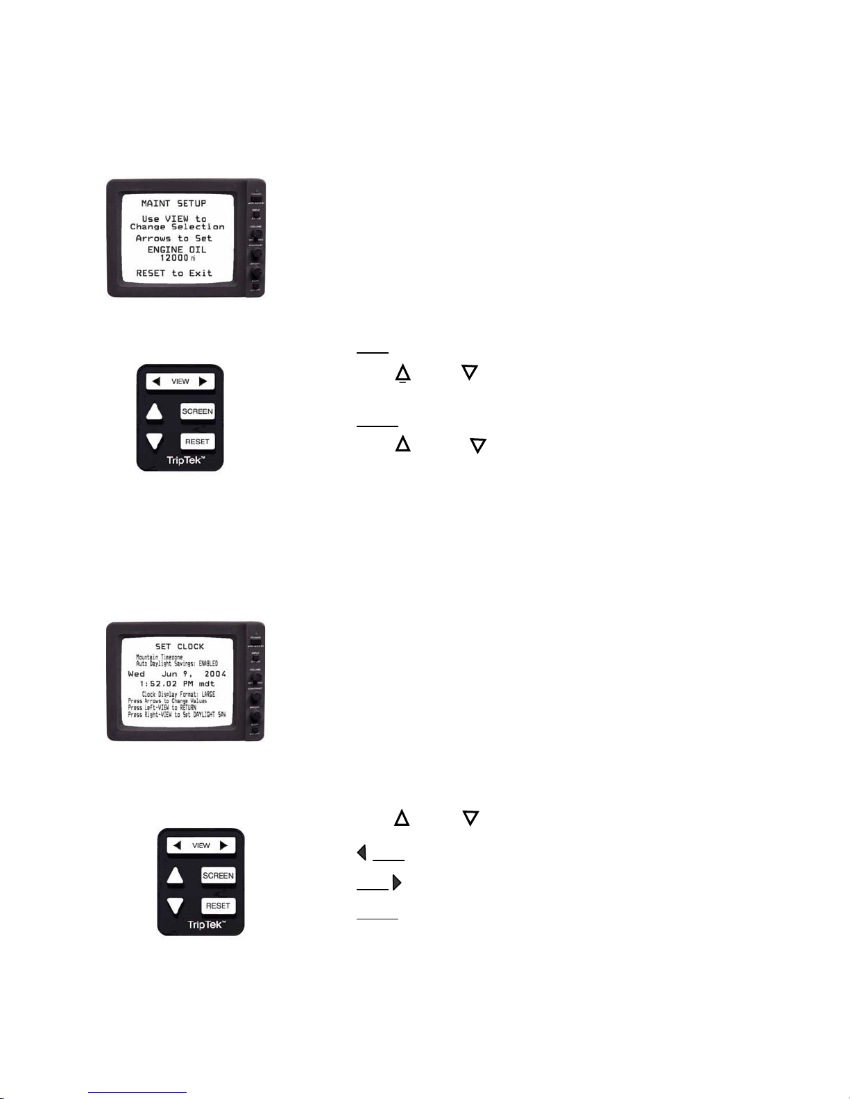
The MAINTENANCE SETUP screen is to preset the service interval of miles or hours.
Maintenance Setup Screen
Engine Oil:
12000 mi: Resetable miles or hours for maintenance
Press VIEW
Press the up ___ or down ___ key to set desired miles (eng or trans) or hours
(genset) for maintenance replacement interval.
Press RESET
Press the up ___ and down ___ key simultaneously to return to the “SCREEN
SELECTION” screen.
Selected maintenance item to set. Ref. Engine Oil,
key to change maintenance line item.
to exit back to “TODAY” screen.
Eng. Fuel Filter, Transmission Oil, Generator Oil
and Fuel Filter
replacement interval.
Set Clock Screen
The SET CLOCK screen is used to set all parameters of the clock
Mountain Timezone: Time zone within the United States/Canada.
Auto Daylight Savings: Able to DISABLE or ENABLE.
Wed Jun 9 2004: Month, Day and Year
1:52.02 PM mdt: Time, am/pm and Time zone
designation.
Clock Display Format: Clock data line and text size.
Large: 1
Small: 1
Press the up ___ or down ___ key to change value of the item blinking.
Press VIEW
Press VIEW key to go forward to next settable item.
Press RESET
key to go back one from the blinking item.
key to return to SCREEN SELECTION screen.
:52 Wed. Jun 9
:52 PM mdt Wed. Jun 9, 2004
Page 11
Page 15
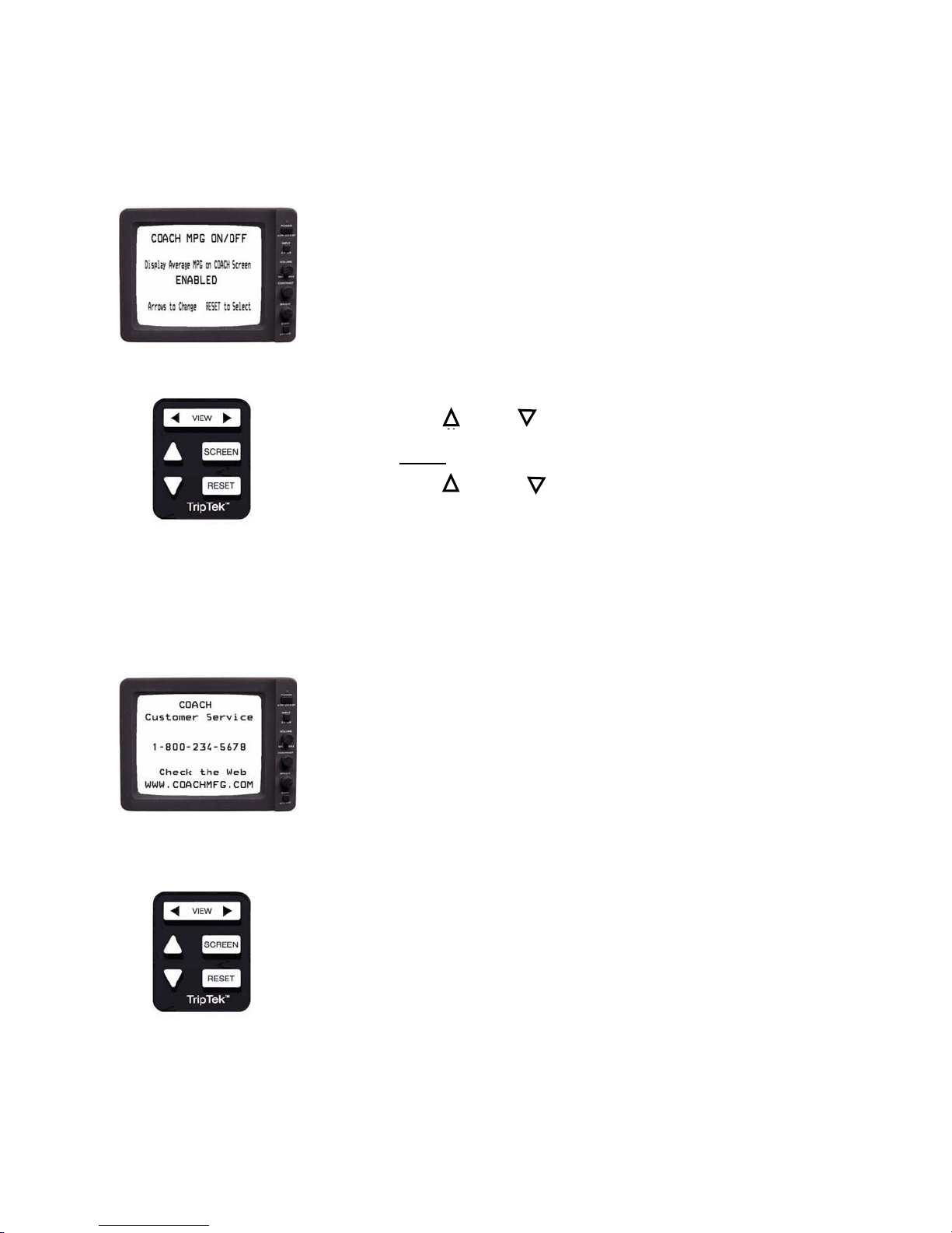
Coach MPG ON/OFF Screen
The COACH MPG ON/OFF screen is to give operator a way of turning MPG Average on or off. This is lifetime
data that is on the COACH screen.
ENABLED: The ability to disable or enable MPG Average on
the COACH screen.
Press the up ___ or down ___ key to disable or enable MPG Average.
Press RESET
Press the up ___ and down ___ keys simultaneously to return to the “SCREEN
SELECTION” screen.
key to select option and return to TODAY screen.
Customer Service Screen
The CUSTOMER SERVICE screen is to give operator easy access to phone numbers and web page of the coach
manufacturer
Phone number of customer service department for
coach manufacturer.
1-800-:
www. : Web page of coach manufacturer.
Press any key to return to the “TODAY” screen.
Page 12
Page 16

TripTek Product Warranty
Coretronics, Inc. (the Company) warrants the Triptek computer to be free of defects in material and
workmanship under normal use and service maintenance for a period of 12 months. In the event the
Computer shall prove to be defective in material or workmanship during said 12-month warranty
period, Coretronics, Inc. will, at its option, repair or replace the Computer, at no charge to Customer
except as set forth below. All replaced parts and equipment shall become the property of Coretronics.
This limited warranty does not apply to any damage to the Computer resulting from accident, physical
or electrical misuse or abuse, improper installation, alteration, any use contrary to its intended function,
unauthorized service (i.e. service by anyone other than the Company or its authorized service
personnel), fire, flood, lighting, or other acts of God.
This warranty limits the Company’s liability to the repair or replacement of the product. The Company
shall not be responsible for removal and/or reinstallation charges, loss or damage in transit and shipping
and mailing costs to the warranty service location.
The Company reserves the right to make changes or improvements in its products without incurring
any obligation to similarly alter products previously purchased.
Page 17

C ORTRONICS, INC.
(208) 938-6331 EAGLE, IDAHO
Page 18

DANGER!
LOW TIRE PRESSURE
Reduce Accident Risk
Increase Fuel Economy
Avoid Inconvenience
Extend Tire Life
Active Tire Pressure Monitoring
There are few situations more stressful, dangerous, and inconvenient than
having a tire blowout when traveling at highway speed. The fact is that most
blowouts can be traced back to damage suffered from prolonged driving on
under-inflated tires. It’s frightening, but studies show that almost half of all RV
tires are under-inflated. The TripTek Tire system is a tire pressure monitoring
system specifically designed to meet the unique needs of RV’s. The system
constantly monitors your tires and warns you of a tire problem before it becomes
dangerous.
Sensors mounted securely to the rim using
stainless steel straps measure internal tire
pressure and temperature. This information is
wirelessly transmitted to a receiver mounted in
the vehicle.
Page 19
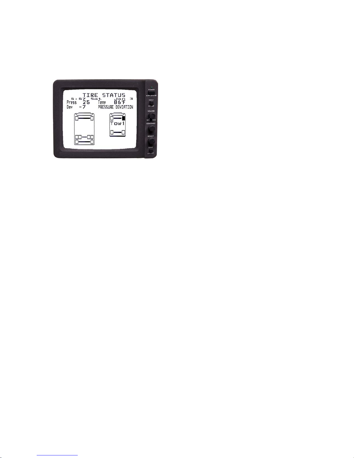
THREE LEVELS OF ALERT
The tire status screen displays all
pertinent data including pressure,
temperature and pressure deviation for
the selected tire. When an alert occurs,
the tire status screen will be displayed to
indicate the affected tire, its status and a
description of the alert.
Pressure Deviation Alert
The Pressure Deviation Alert is initiated when the measured tire pressure
deviates from the required pressure by more than the preset level. This is the
first warning of an under-inflated tire. When the pressure falls below the first
programmed level, TripTek alerts the driver with a warning light, audible alarm
and displayed information.
Critical Low Pressure Alert
The Critical Low Pressure Alert warns the driver when the tire pressure falls
below the second programmed level. This audible and visual warning alerts the
driver to take immediate precautions.
High Temperature Alert
The High Temperature Alert warns the driver when the tire temperature exceeds
a programmed level. This can indicate a serious tire problem or possibly a brake
or bearing problem that requires immediate attention.
And More …
• Displays all tire status on one screen.
• Tracks all warnings (tire log) to assist in managing problems.
• Temperature compensation profile is auto set by system.
• Can check tire status while parked.
• Stores in memory your primary vehicle and up to three towed vehicles.
• Monitors up to 28 wheels simultaneously and 56 total wheel positions.
Coretronics, Inc.
1251 E. Iron Eagle Drive, Suite 100, Eagle, Id 83616
2208-938-6331 www.TripTek.net
Page 20
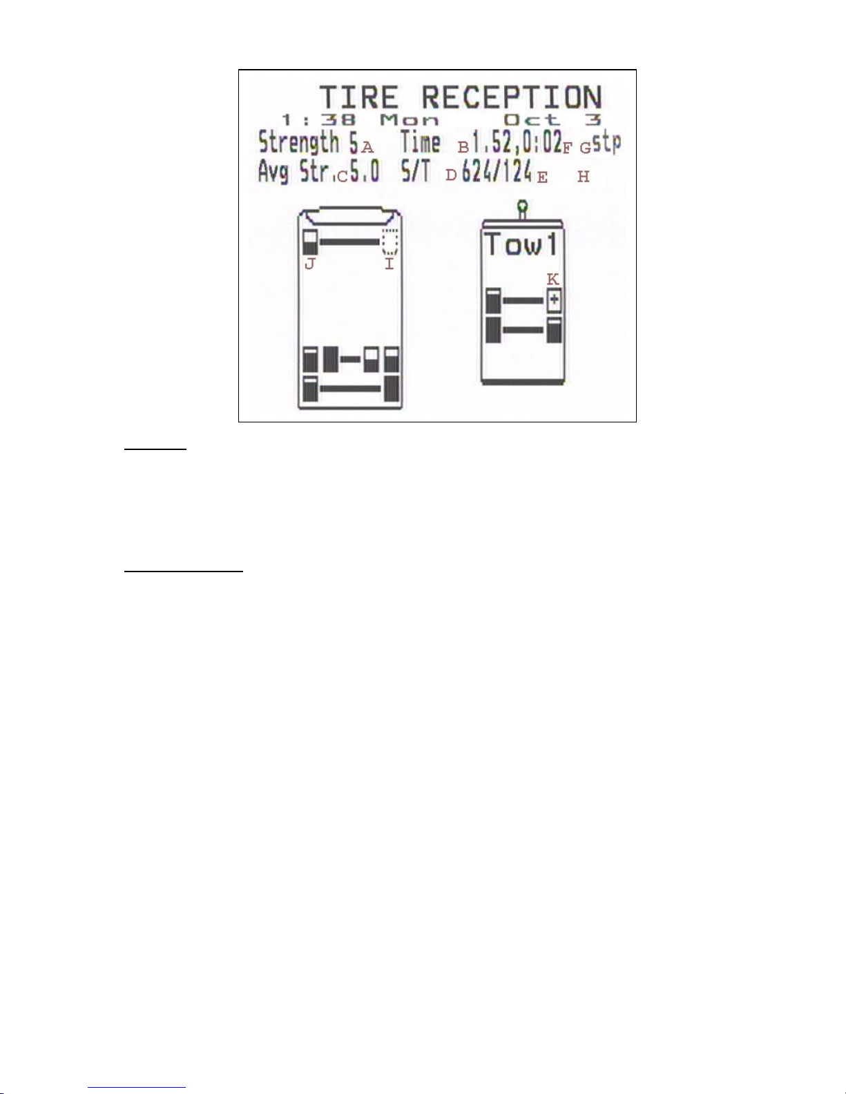
Password
From the ‘CONFIG TIRE’ menu press in sequ ence:
RESET, DOWN, UP, DOWN, RESET, L+R VIEW (together)
Any mistake will reset the sequence. When the sequence has been entered correctly a new line
item ‘Check Signal Strength’ will appear in the menu. This item will be enabled until TripTek is
powered down (typically 90 min after the shutdown of the vehicle).
Screen Data Items
A. Strength of the last transmission. This data parameter is not saved at power down or after
changing tow vehicle. While driving this number will change from time to time reflecting the
most recent data from the tire. Tires with g ood reception will occasionally get a poor signal
strength transmission depending on the wheel position of the vehicle during the transmission.
B. Time since last transmission. This is in the minutes.seconds format. This timer is not running
when the vehicle is traveling less than 10mph . A new transmission zeros out this timer. The
time is accurate to the nearest 7.5 second boundary.
C. Average signal strength. This parameter is the average of every signal strength value for a
given tire received since the last reset.
D. Total of all received signal strengths.
E. Number of transmissions received since the last reset. (note that D/E = C)
F. Time the vehicle has traveled at a speed of more than 10 mph since the last reset. This
parameter is in the hours:minutes format and gives an indication of how long the vehicle has
been running.
G. Stop indicator. When ‘ stp’ appears the coach is considered ‘stop ped’ and timers B and F are
held stationary.
H. Overflow indicator. When ‘ovr’ appears, TripTek has accumulated as much data as it can.
Future transmissions will not affect the n umbers C, D, or E.
I. Dotted tire: A dotted tire indicates no new signal stren gth data is available for this tire.
J. Bar graph tire: Tires for which data exists h ave a small bar graph contained within them. This
represents the currently selected parameter (A,B,C,D or E) as explained in the next section.
K. Tire with Plus: A tire with a plus indicates that the receiver is in the middle of receiving a
transmission from the indicated tire.
Page 21
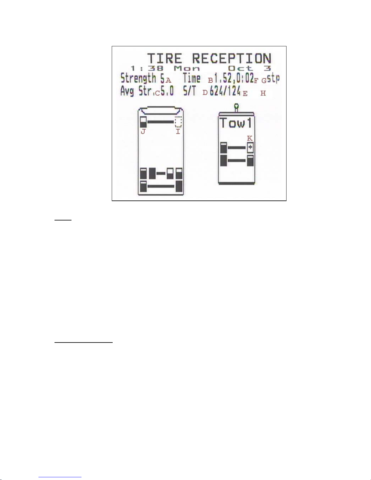
Usage
Pressing UP/DOWN will select a tire within the TIRE RECEPTION screen. The currently
selected tire is the one that is blinking.
Pressing left VIEW will exit the TIRE RECEPTION screen.
Pressing RESET will reset the signal strength data for the vehicle the cursor is curr ently on.
(Data values B, C, D, E, and F).
Pressing SCREEN will change the current ly selected parameter. The current parameter is the
data item, which is blinking (item A, B, C, D or E) . When a parameter is selected (say parameter
C, the average signal strength) then each of the bar graphs within the tires of the vehicl e will
represent the relative strength of the selected parameter. There are 7 possible gr aduations (from 0
to 6 bars) within the miniature graphs. They are mapped as follows:
Tire Bar Graph Key
A. Strength (last transmission): strength of 0-1 = 0 bars, strength of 2 = 1 bar, …. , strength of 7
or greater = 6 bars.
B. Last transmission timestamp: 0-8 min. ago = 6 bars, 8-12 min. ago = 5 bars, 12-16 min. ago =
4 bars, 16-20 min. ago = 3 bars, 20-24 min. ago = 2 bars, 24-28 min. ago = 1 bar, 28 min or
greater 0 bars.
C. Strength (average): strength of 0-1.9 average = 0 bars, strength of 2.0-2.9 average = 1 bar,
…., strength of 7.0 average or greater 6 bars.
D. Total of all received signal strengths: The bar graph represents a percentage of the maximum
total signal strength seen on any tire o f the given vehicle. Vehicles are considered separately.
For instance if the bar graph on one tire is half filled this means that the tire has a lower
signal quality than one that has a filled t ire from the same vehicle.
E. Number of transmissions: The bar graph r epresents a percentage of the maximum number of
transmissions seen on any tire of the vehicle. Vehicles are considered separately. For instance
if the bar graph on one tire is half filled this means that the tire has received half the nu mber
of transmissions as the tire with a filled tir e f r om the same vehicle.
 Loading...