

Page 1
WB01 User Manual
WiFi 11a/b/g/n/ac 2T2R and BT4.0 Module
Page 2

Agenda
▪ SOP- How to install WiFi Driver
▪ SOP - How to WiFi Tool
▪ SOP- How to install USB BT Tool and Driver
– Update USB driver:
• Update USB driver_Method_A
• Update USB driver_Method_B
– BT Tool in WCN Combo Tool:
• COM and Download patch
▪ SOP - How to use BT Tool
– BT Tool:
1. Setting page
2. RF Test page for BR & EDR TX-Mode
3. BLE Test mode page for LE TX/RX-Mode
4. Non-signaling RX Test page for BR & EDR RX-Mode
5. TX tone Test page for BR/EDR/LE continuous TX-Mode
for Bluetooth Test-Mode
Page 3

SOP-
How to install WiFi Driver
(Only support win XP & win7)
Page 4
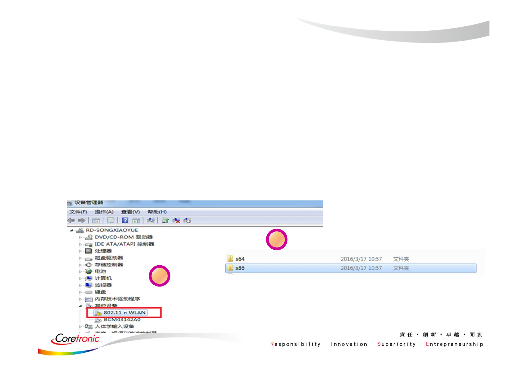
Update WiFi driver
1. Insert the WIFI module。
2. Select “WLAN” device to install WIFI driver.
3. If there is any driver needed, please choose the folder mentioned by step3.
(Skip the BT Hardware Installtion, the BT driver and WIFI driver should
better be installed separately.)
4. The Installation is complete.
3
2
Page 5

SOP - How to use WiFi Tool
Page 6
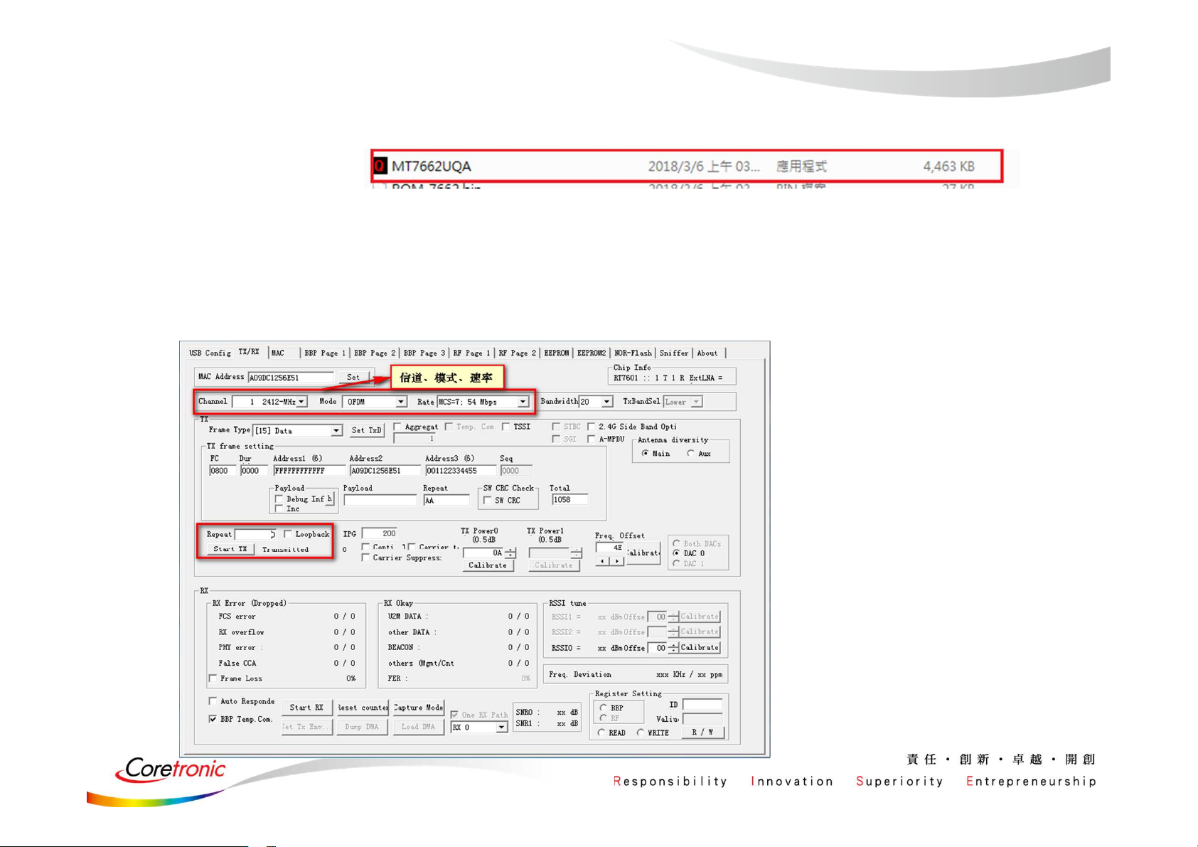
WiFi Tool
1. Click the icon
2. Enter the following interface
3. Select the Channel / Rate / Bandwidth .
According to the setup outline in red, click the start TX.(Repeat change to “0”)
Page 7

SOP-
How to install USB BT Tool
and Driver
(Only support win7 32 bit)
Page 8
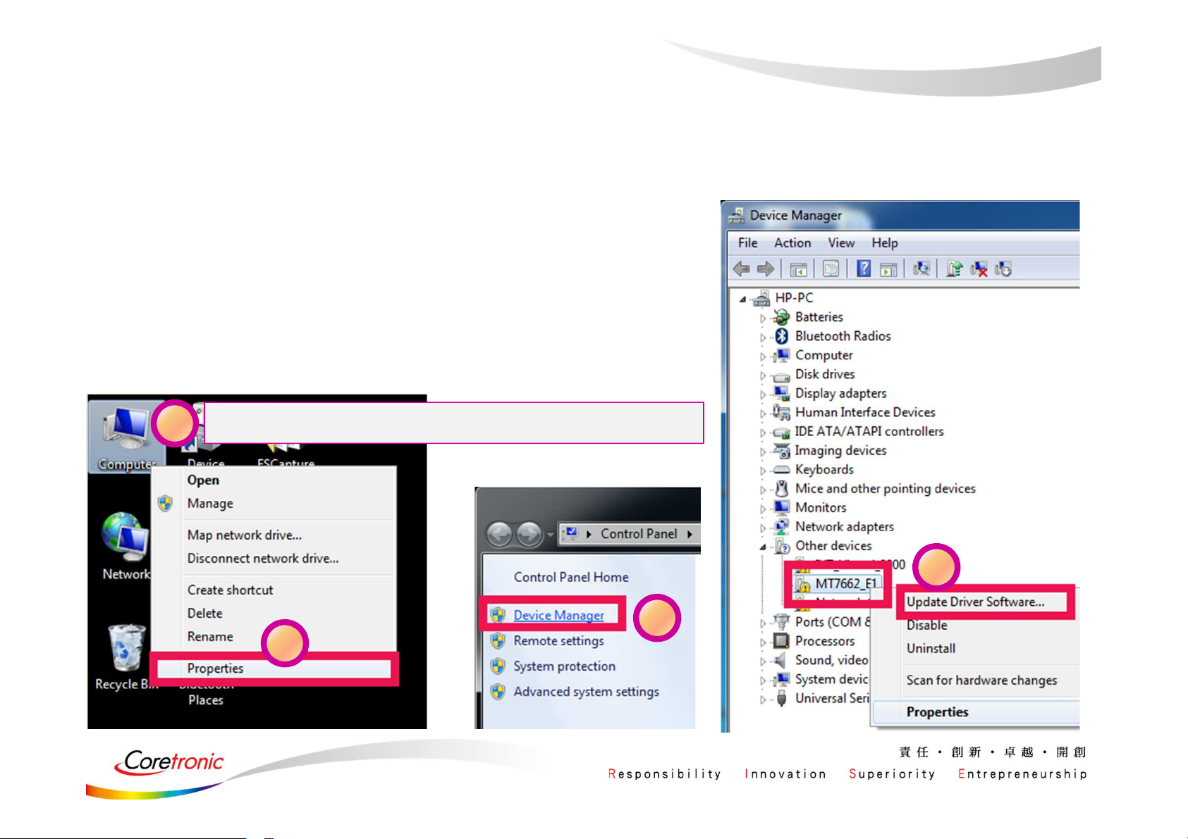
Update USB driver
1. Plug in the USB DUT
2. Go to the “Device Manager”
3. Select “BT” device to install BT driver.
1
Click right of the mouse over “Computer”
4
3
2
Page 9
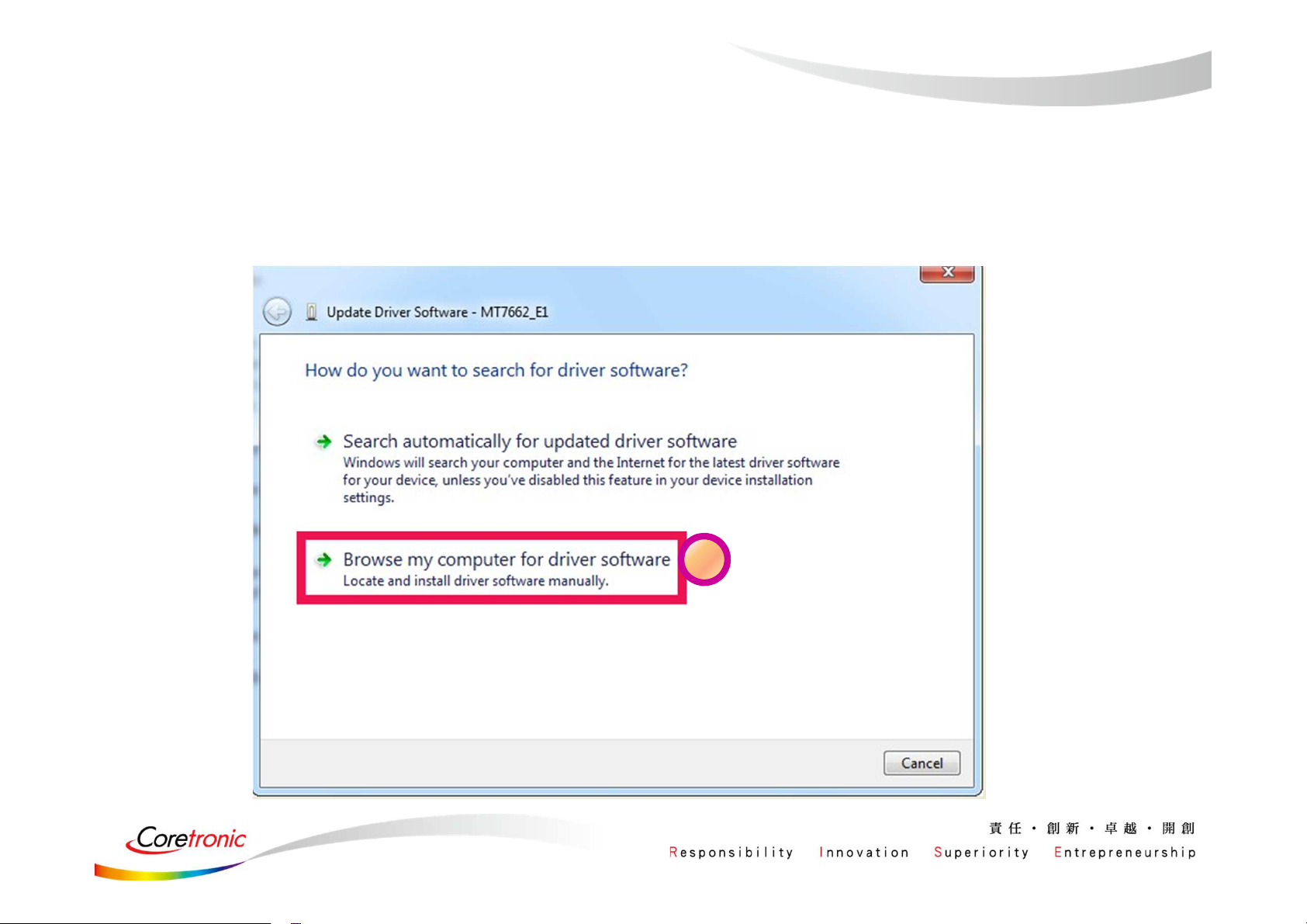
Update USB driver (Cont.)
5
Page 10
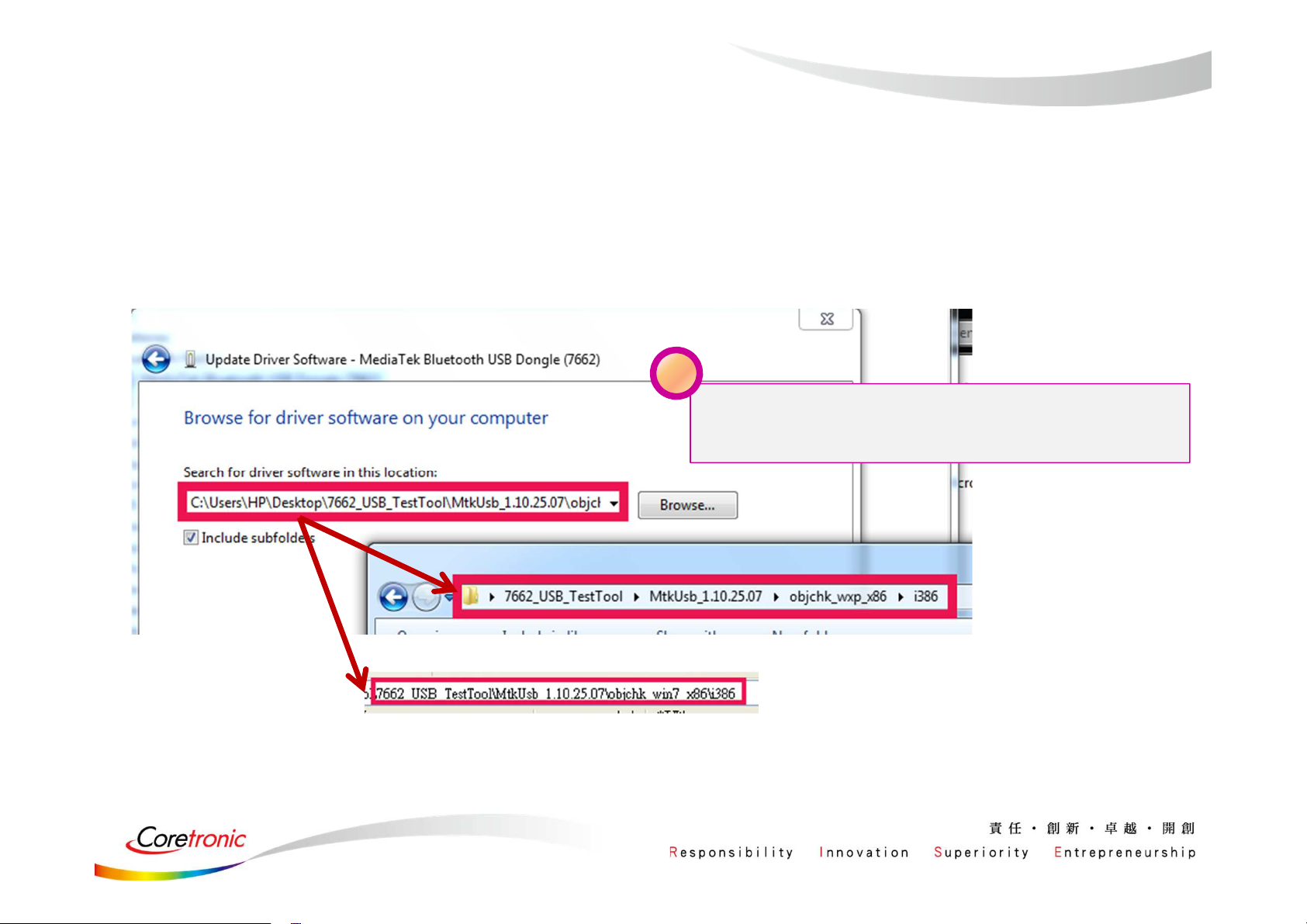
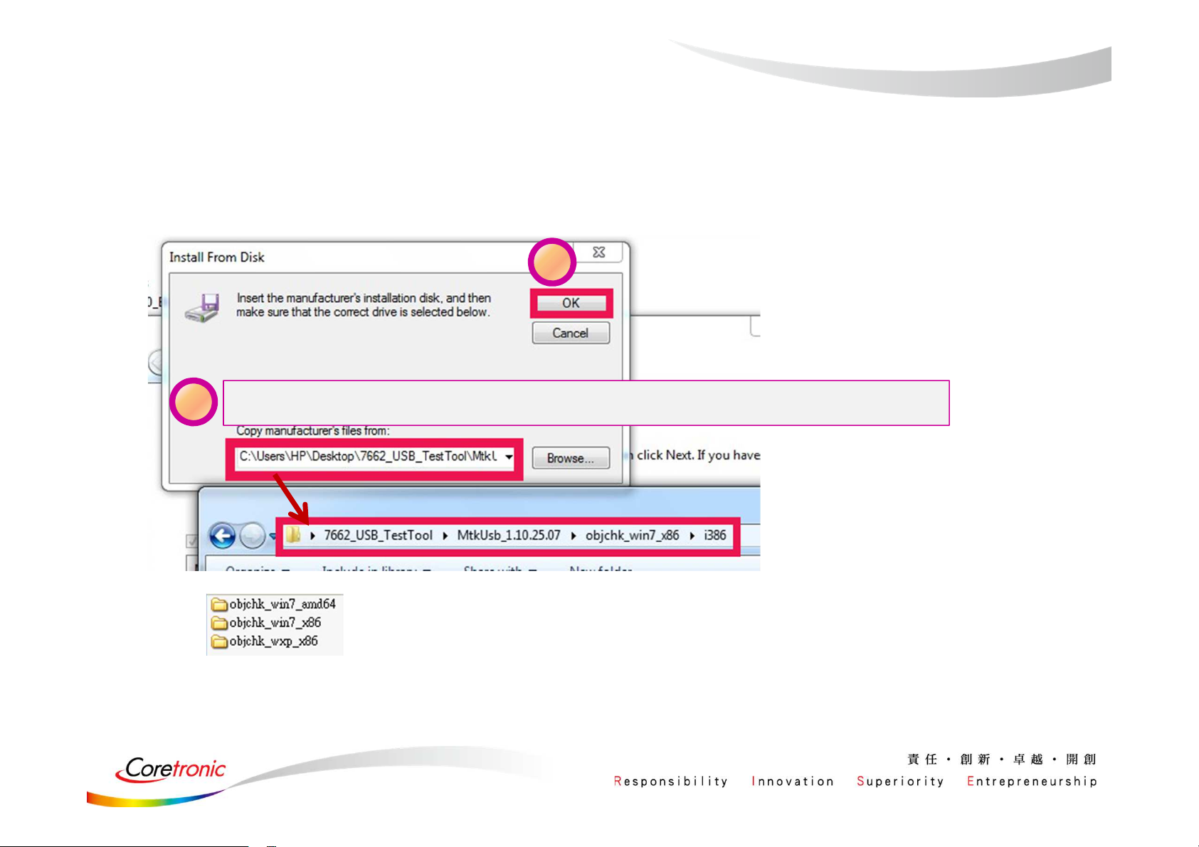
Update USB driver_Method_A
6
Please according to your OS type to
choose the related folder
or
Page 11
Update USB driver_Method_A
(cont.)
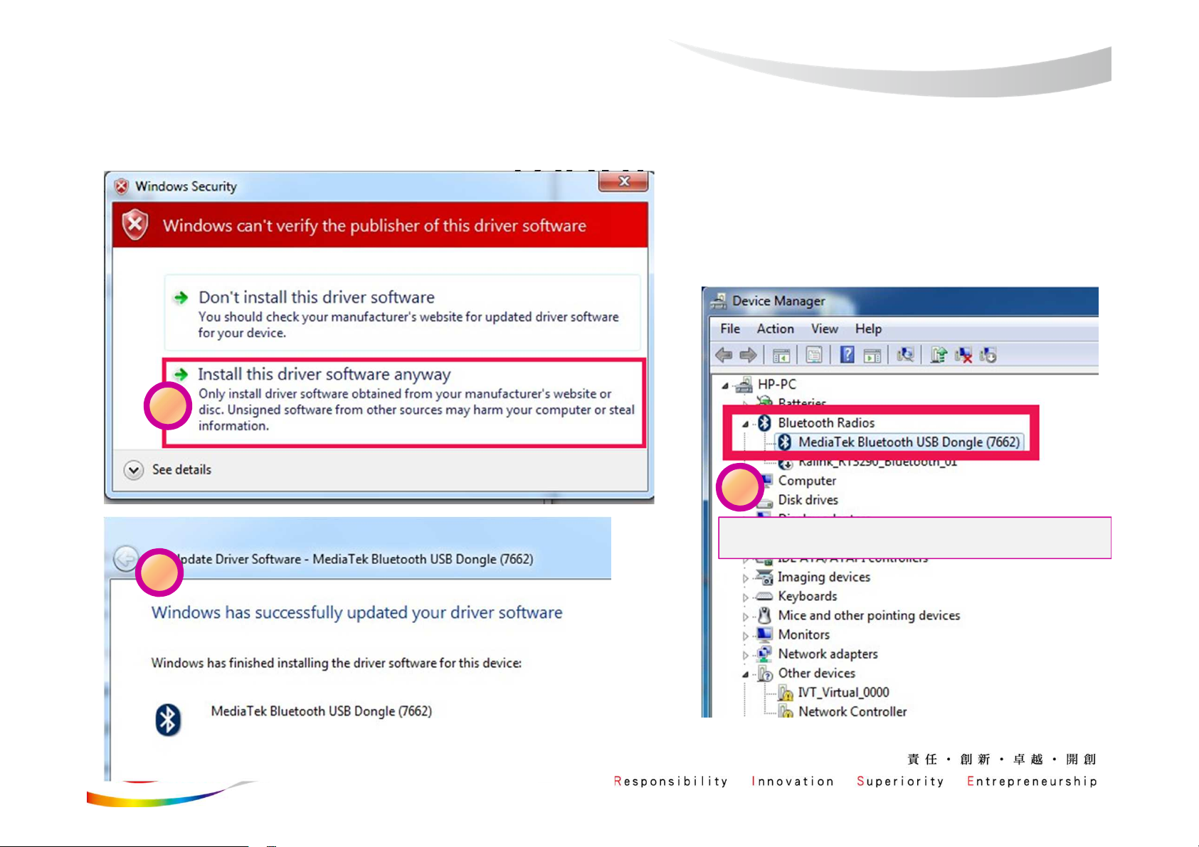
7
9
8
Test driver update successfully!
Page 12
Update USB driver_Method_B
6
Page 13

Update USB driver_Method_B
(Cont.)
7
Page 14
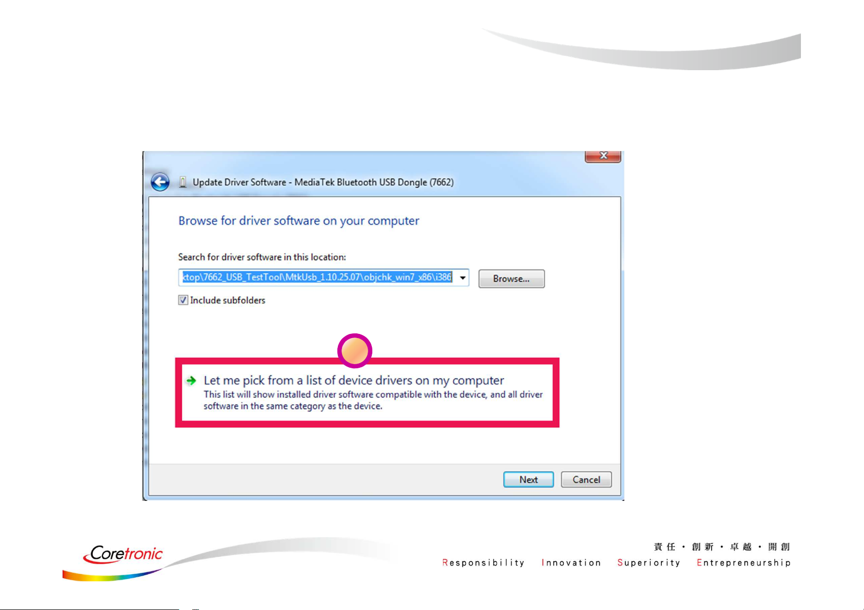
Update USB driver_Method_B
(Cont.)
9
8
Choose the folder according to your OS type
Page 15

Update USB driver_Method_B
(Cont.)
10
Select this driver
11
Page 16

Update USB driver_Method_B
(Cont.)
12
14
13
Test driver update successfully!
Page 17

WCN Combo Tool
• Install BT tool: WCN_Combo_Tool_Setup.exe
Page 18

SOP - How to use BT Tool
Page 19

Installation“WCN_Combo_Tool_Setup_customer”,
Click“BT_Tool.exe”
Page 20

BT Tool in WCN Combo Tool
• BT Tool:
1. Setting page
2. RF Test page for BR & EDR TX-Mode
3. BLE Test mode page for LE TX/RX-Mode
4. Non-signaling RX Test page for BR & EDR RX-Mode
5. TX tone Test page for BR/EDR/LE continuous TX-Mode
for Bluetooth Test-Mode
Page 21

How to use BT Tool
• BT Tool:
• Open / Close COM
1. Setting page
2. RF Test page for BR & EDR TX-Mode
3. BLE Test mode page for LE TX/RX-Mode
4. Non-signaling RX Test page for BR & EDR RX-Mode
5. TX tone Test page for BR/EDR/LE continuous TX-Mode
for Bluetooth Test-Mode
• Read BD Address
• Enter Test Mode
Page 22

Read BD Address
1. Ensure BT COM port is opened and “RESET Device” button is clicked.
2. Click “Read” button.
3. BD Address is updated
1
2
3
22
Page 23

Enter Test Mode
1. Ensure BT COM port is opened and “RESET Device” button is clicked.
2. Click “Enter DUT” button to allow DUT to enter test mode.
3. The connection between DUT and test set (ex: CBT) could be established
under test mode.
2
23
Page 24

• BT Tool:
Agenda
1. Setting page for Bluetooth Test-Mode
2. RF Test page for BR & EDR TX-Mode
3. BLE Test mode page for LE TX/RX-Mode
4. Non-signaling RX Test page for BR & EDR RX-Mode
5. TX tone Test page for BR/EDR/LE continuous TX-Mode
• Reset Device
• BR & EDR TX Mode
• Tx Power Control
• Hopping/Single Frequency
Page 25

Reset Device
1. Ensure BT COM port is opened and “RESET Device” button is clicked.
2. Click “Reset Device” button to Reset DUT.
3. HCI RX event is responded (RX: 0E 04 01 03 0C 00)
1
25
Page 26

BR & EDR TX Mode
1. Ensure BT COM port is opened and “RESET Device” button is clicked.
2. Set pattern type, packet type, and signal Frequency. And then Click “Start” button.
3. Check Tx power of DUT by test set (ex: CBT).
4. Click “Stop” button to end test.
1
26
Page 27

Tx Power Control
1. Ensure BT COM port is opened and “RESET Device” button is clicked.
2. Set pattern type, packet type, and signal Frequency. And then Click “Start” button.
3. Check Tx power of DUT by BT test set (ex: CBT).
4. Select “Tx Power Level” to 6~0, and then see if TX power is correspondly changed.
1
3
27
Page 28

Hopping
M
m
m
• Select “Frequency Hopping”, and then see if TX signal is present on spectrum
analyzer correctly.
*
Ref 10 dBm Att 40 dB
Offset 1 dB
10
1
0
1 PK
AXH
-10
-20
-30
-40
-50
RBW 1 MHz
VBW 3 MHz
SWT 2.5 ms
Marker 2 [T1 ]
4.69 dB
2.480000000 GHz
Marker 1 [T1 ]
2
3.72 dB
2.402000000 GHz
A
LVL
3DB
-60
-70
-80
-90
Center 2.45 GHz Span 100 MHz10 MHz/
Frequency Hopping
28
Page 29

Single Frequency
V
A
M
M
m
V
A
m
V
A
M
M
m
Select “Single Frequency”, and then change the channel number
(00~78) ,TX signal is present on spectrum analyzer correspondingly
Ref 10 dBm
Offset 1 dB
10
1
0
1 PK
AXH
-10
-20
-30
-40
-50
-60
-70
-80
-90
Center 2.45 GHz Span 100 MHz10 MHz/
tt 40 dB
RBW 3 MHz
BW 10 MHz
SWT 2.5 ms
arker 1 [T1 ]
3.98 dB
2.402000000 GHz
.
RBW 3 MHz
BW 10 MHz
Ref 10 dBm
Offset 1 dB
A
LVL
3DB
10
0
1 PK
MAXH
-10
-20
-30
-40
-50
-60
-70
-80
-90
Center 2.45 GHz Span 100 MHz10 MHz/
tt 40 dB
SWT 2.5 ms
1
Marker 1 [T1 ]
4.35 dB
2.441000000 GHz
Ref 10 dBm
Offset 1 dB
10
A
LVL
3DB
0
1 PK
AXH
-10
-20
-30
-40
-50
-60
-70
-80
-90
Center 2.45 GHz Span 100 MHz10 MHz/
tt 40 dB
RBW 3 MHz
BW 10 MHz
SWT 2.5 ms
arker 1 [T1 ]
4.87 dB
2.480000000 GHz
1
A
LVL
3DB
0ch
39ch 78ch
Page 30

• BT Tool:
1. Setting page for Bluetooth Test-Mode
Agenda
2. RF Test page for BR & EDR TX-Mode
3. BLE Test mode page for LE TX/RX-Mode
4. Non-signaling RX Test page for BR & EDR RX-Mode
5. TX tone Test page for BR/EDR/LE continuous TX-Mode
• BLE Test Mode – TX
• BLE Test Mode – RX
Page 31

BLE Test Mode - TX
1. Ensure BT COM port is opened and “RESET Device” button is clicked.
2. Set RF channel and Pattern type on CBT to analyze DUT TX performance.
3. Select TX frequency (00~39) and Tx pattern. Then click “Start” button.
4. TX signal is present on CBT correspondingly.
5. Click “Stop” button to end LE TX test.
3
Page 32

BLE Test Mode - RX
1. Ensure BT COM port is opened and “RESET Device” button is clicked.
2. Set Rx Level, RF channel, and Pattern Type on CBT. Then Turn on generator.
3. Select RX frequency (00~39) and Rx pattern. Then click “Start” button.
4. Click “Stop” button.
3
PER result are shown in below.
4
Page 33

• BT Tool:
1. Setting page for Bluetooth Test-Mode
2. RF Test page for BR & EDR TX-Mode
3. BLE Test mode page for LE TX/RX-Mode
4. Non-signaling RX Test page for BR & EDR
RX-Mode
Agenda
5. TX tone Test page for BR/EDR/LE continuous
TX-Mode
Page 34

Non-Signaling RX Test
1. Ensure BT COM port is opened and “RESET Device” button is clicked.
2. Set Rx Level, RF channel, Packet Type, Pattern Type, and BD address (ex:
000000A5F0C3) on CBT. Then Turn on generator.
3. Select Rx pattern, RX frequency (00~78), Packet Type, and Tester Address (ex:
000000A5F0C3, please fill “00A5F0C3”). Then click “Enter Test” button.
4. Click “End Test” button.
3
PER/BER result are shown in right side.
4
Page 35

• BT Tool:
Agenda
• Single Tone
1. Setting page for Bluetooth Test-Mode
(CW mode TX)
• Modulation Tone
2. RF Test page for BR & EDR TX-Mode
(Continuous mode TX)
3. BLE Test mode page for LE TX/RX-Mode
4. Non-signaling RX Test page for BR & EDR
RX-Mode
5. TX tone Test page for BR/EDR/LE continuous
TX-Mode
Page 36

Single Tone – CW tone TX (No modulated signal)
A
M
m
1. Ensure BT COM port is opened and “RESET Device” button is clicked.
2. Select Tone Type (ex: Single_Tone_DC), and then change the channel number (00~78)
3. Click “Enter Test” button.
TX signal is present on spectrum analyzer correspondingly.
4. Click “HCI Reset” button to end test.
1
2
1 PK
AXH
2 AP
CLRWR
Ref 20 dBm
20
10
0
-10
-20
-30
-40
-50
-60
-70
-80
*
tt 30 dB
*
RBW 10 kHz
VBW 30 kHz
SWT 20 ms
1
200 kHz/Center 2.402 GHz Span 2 MHz
Marker 1 [T1 ]
8.81 dB
2.401992000 GHz
A
Page 37

Modulation Tone – Continuous mode TX
A
M
m
1. Ensure BT COM port is opened and “RESET Device” button is clicked.
2. Select “Modulation_Tone”, and then change the channel number (00~78).
Choose mode (BT-GFSK/EDR or LE) and Modulation rate (1M/2M/3M)
3. Click “Enter Test” button.
TX signal is present on spectrum analyzer correspondingly.
4. Click “HCI Reset” button to end test.
1
2
1 PK
AXH
2 AP
CLRWR
Ref 20 dBm
20
10
0
-10
-20
-30
-40
-50
-60
-70
-80
*
tt 30 dB
*
RBW 10 kHz
VBW 30 kHz
SWT 20 ms
1
200 kHz/Center 2.402 GHz Span 2 MHz
Marker 1 [T1 ]
8.81 dB
2.401992000 GHz
A
Page 38

Real COM Relay
2018/
Copyright © MediaTek Inc.
38
6/22
All rights reserved.
Page 39

Real COM Relay (1/3)
• Test setup:
– Relay RS232 data by PC:
BT test set
(CBT)
1. USB to RS232 + Cross TX/RX cable
2. USB for DUT
RS232
DUT
RS232 cable
RS232
Cross TX/RX
RS232
USB to
RS232 cable
Real COM Relay
USB
PC
USB
DUT
Copyright © MediaTek Inc.
All rights reserved.
2018/
6/22
39
Page 40

Real COM Relay (2/3)
1. Ensure BT COM port is opened and “RESET Device” button is clicked.
2. Click “Enter DUT” button to allow DUT to enter test mode.
3. Close BT COM port. Click “Stop Relay”.
4. Click “Config Use virtual COM”
5. Select COM port of “USB to RS232 cable”
for example: COM 1 for “USB to RS232 cable”, please choose “COM1”
Copyright © MediaTek Inc.
All rights reserved.
2018/
6/22
40
Page 41

Real COM Relay (3/3)
1. Click “Start Relay” button for Real COM relay.
Copyright © MediaTek Inc.
All rights reserved.
2018/
6/22
41
Page 42

NCC
• 第十二條 經型式認證合格之低功率射頻電機,非經許可,公司、商號或使用者均不得擅自變更頻率、加大功率或變更
原設計之特性及功能。
• 第十四條 低功率射頻電機之使用不得影響飛航安全及干擾合法通信;經發現有干擾現象時,應立即停用,並改善至無
干擾時方得繼續使用。
前項合法通信,指依電信法規定作業之無線電通信。
低功率射頻電機須忍受合法通信或工業、科學及醫療用電波輻射性電機設備之干擾。
• 使用此產品時應避免影響附近雷達系統之操作。
• 高增益指向性天線只得應用於固定式點對點系統。
1. 本模組於取得認證後將依規定於模組本體標示審驗合格標籤。
2. 系統廠商應於平台上標示「本產品內含射頻模組: XXXyyyLPDzzzz-x」字樣。
電信管制射頻器材警語
低功率電波輻射性電機管理辦法
模組認證:
Page 43

Federal Communication Commission Interference Statement
• This device complies with Part 15 of the FCC Rules. Operation is subject to the following two conditions: (1) This
device may not cause harmful interference, and (2) this device must accept any interference received, including
interference that may cause undesired operation.
• This equipment has been tested and found to comply with the limits for a Class B digital device, pursuant to Part 15
of the FCC Rules. These limits are designed to provide reasonable protection against harmful interference in a
residential installation. This equipment generates, uses and can radiate radio frequency energy and, if not installed
and used in accordance with the instructions, may cause harmful interference to radio communications. However,
there is no guarantee that interference will not occur in a particular installation. If this equipment does cause harmful
interference to radio or television reception, which can be determined by turning the equipment off and on, the user is
encouraged to try to correct the interference by one of the following measures:
• - Reorient or relocate the receiving antenna.
• - Increase the separation between the equipment and receiver.
• - Connect the equipment into an outlet on a circuit different from that to which the receiver is connected.
• - Consult the dealer or an experienced radio/TV technician for help.
• FCC Caution: Any changes or modifications not expressly approved by the party responsible for compliance could
void the user's authority to operate this equipment.
Page 44

Federal Communication Commission Interference Statement
• This transmitter must not be co-located or operating in conjunction with any other antenna or transmitter.
• Operations in the 5.15-5.25GHz band are restricted to indoor usage only.
• FOR MOBILE DEVICE USAGE (>20cm/low power)
• Radiation Exposure Statement :
This equipment complies with FCC radiation exposure limits set forth for an uncontrolled environment. This
equipment should be installed and operated with minimum distance 20cm between the radiator & your body.
• This device is intended only for OEM integrators under the following conditions:
1) The antenna must be installed such that 20 cm is maintained between the antenna and users, and (if EUT is
portable device, please delete this item)
2) The transmitter module may not be co-located with any other transmitter or antenna.
• As long as 2 conditions above are met, further transmitter test will not be required. However, the OEM integrator is
still responsible for testing their end-product for any additional compliance requirements required with this module
installed
Page 45

Federal Communication Commission Interference Statement
• IMPORTANT NOTE: In the event that these conditions can not be met (for example certain laptop configurations or
co-location with another transmitter), then the FCC authorization is no longer considered valid and the FCC ID can
not be used on the final product. In these circumstances, the OEM integrator will be responsible for re-evaluating the
end product (including the transmitter) and obtaining a separate FCC authorization.
• End Product Labeling
FOR MOBILE DEVICE USAGE (>20cm/low power)
This transmitter module is authorized only for use in device where the antenna may be installed such that 20 cm may
be maintained between the antenna and users. The final end product must be labeled in a visible area with the
following: “Contains FCC ID:SUZ-WB01”. The grantee's FCC ID can be used only when all FCC compliance
requirements are met.
• Manual Information To the End User
The OEM integrator has to be aware not to provide information to the end user regarding how to install or remove this
RF module in the user’s manual of the end product which integrates this module.
The end user manual shall include all required regulatory information/warning as show in this manual.
 Loading...