

Page 1

INSTALLATION AND OPERATING INSTRUCTIONS
Revision Date: March 3, 2010
VCX-4400-E MPEG-4 Encoder, IP
VCX-4400-ER MPEG-4 Encoder, IP Rack Mount
Core Tec Communications, LLC
2950 Lake Emma Rd
Suite 1030
Lake Mary, FL 32746 USA
Phone (407) 331-0547
Fax (407) 331 0656
www.coretec.com
Technical Support:
U.S. 877-331-0547
(Toll Free)
Elsewhere: 407-331-0547
Page 2

TableofContents
Introduction ..................................................................................................................................... 3
Familiarization with the VCX4400-E ......................................................................................... 4
Familiarization with the VCX4400-E ......................................................................................... 4
Com Port Data Interface ............................................................................................................. 5
Video Input Interface .................................................................................................................. 5
Ethernet Interface ........................................................................................................................ 5
Power .......................................................................................................................................... 5
Display ........................................................................................................................................ 5
Mounting the Encoder ................................................................................................................. 6
Quick Start ...................................................................................................................................... 6
If user wishes to configure settings with VCX4400-E via COM Port or Network: ................... 6
Updating Firmware with VCXNetBurner ....................................................................................... 8
IP Configuration............................................................................................................................ 18
Overview ................................................................................................................................... 18
Initial IP Addressing ................................................................................................................. 19
Connecting to Unit ........................................................................................................................ 21
Program Commands...................................................................................................................... 23
Network Setup .......................................................................................................................... 23
Common Commands ................................................................................................................ 24
Encoder Commands .................................................................................................................. 25
COM Port Setup ........................................................................................................................ 25
OSD COMMANDS (On Screen Display) ................................................................................ 28
Video Commands...................................................................................................................... 28
SAP Settings ............................................................................................................................. 30
Miscellaneous Settings .............................................................................................................. 32
Specifications ................................................................................................................................ 33
Model Numbers ............................................................................................................................ 35
Appendix A ................................................................................................................................... 36
Pinouts....................................................................................................................................... 36
Com Port Data Interface Pin Out (uses RJ-45 Plug)............................................................. 36
Standard Ethernet Pin Out .................................................................................................... 36
RJ-11 to Serial Interface Adaptor Pinout .............................................................................. 37
Troubleshooting ........................................................................................................................ 38
Page 3

Introduction
The VCX-4400-E and the -ER are the chassis versions of the Core Tec stand-alone VCX4400 MPEG-4 IP product series. These units are fully compatible with the “-ER” card cage
versions of the product series.
The VCX-4400 Digital Video Codec system consists of a video encoder and a Core Tec
decoder pair providing the capability for one-way end-end transmission of compressed digital
video in IP packets at data rates in the 64kbps to 3.5 Mbps range.
The system employs MPEG-4 encoding. The encoding-decoding process is applied to an
NTSC (or PAL) video input, selected in software.
The video encoder converts the video to a serial signal, which is multiplexed with any
data sub-channels present. The stream is then formatted into a series of IP packets sent to the
network through a standard Ethernet connection.
Modification to video format and resolution, data sub-channel characteristics, and basic
IP parameters are achieved through one of the following means:
a) a Hyper Terminal accessible menu
b) Telnet through the Ethernet connection
c) Watchdog CCS
The video decoder receives the IP packets, separates the video data from the data subchannels, and converts the video data to analog form, providing an NTSC (or PAL) output.
The units feature two bi-directional data sub-channels (programmable for RS-232 or RS-
422). Data bits are multiplexed with the digital data stream.
Page 4

FamiliarizationwiththeVCX4400E
The VCX-4400-E Video Encoder accepts one video and two data signals. The output
from the encoder is a stream of IP- packets. It also contains a fluorescent LED display to allow
monitoring of unit performance and to facilitate troubleshooting. The encoder has a
programmable reset, which prompts the re-initiation of the video stream as well as a reboot
command.
The VCX-4400-D Video Decoder accepts the signal from the network originally generated by a
VCX-4400-E video encoder. The unit effectively decompresses this data stream and re-creates
an analog waveform in NTSC (or PAL) video format. The unit supports the bi-directional data
transmission of two data sub-channels, corresponding to the encoder. The unit also features an
LED display. The decoder also has a programmable reset command, tied to errors in the
incoming video stream, as well as a reboot command.
Front Panel
Control Port
-Used to directly
communicate with
encoder to configure
settings
VCX4400-E-H, Half Size Encoder
Back Panel
Power Supply
Refer to “Power
Interface” in
Table of Contents
VCX4400-E-H, Half Size Encoder
Video Input
Refer to “Video
Interface” in table of
contents
Ethernet
Refer to “Ethernet
Interface” in Table
of Contents
Power
switch
-controls
unit power
the
2 Data Subchannels
Refer to “Com Port
Data Interfaces” in
Table of Contents
Page 5

ComPortDataInterface
There are two bi-directional data interfaces, RS-232 and RS-422 selectable, on the encoder and
decoder assemblies. Each interface uses RJ-45 connectors. Refer to Table below for the correct pin out.
When using the RS-232 configuration pin 7 is ground.
system software.
Refer to Appendix A for the correct pin out
.
Com Port parameters are configured through the
VideoInputInterface
Connect a BNC-terminated coaxial cable from a composite video source (e.g., CCTV camera) to
the BNC connector labeled “VIDEO IN” (encoder). The composite video input should be in NTSC or
PAL format. The maximum length of cable that should be interfaced to the encoder or decoder is 100 feet,
although the specific installation environment will dictate the actual permissible length.
EthernetInterface
There is one Ethernet interface for encoder or decoder, which uses a standard RJ-45 connector.
The standard method of terminating an ETHERNET cable reflects the TIA568A standard
(Telecommunications Industry Association standard).
Refer to Appendix A for the Straight Through and Crossover Ethernet Pin Out.
Power
Power is applied through a standard IEC type detachable line cord at the rear of the unit. The unit
automatically senses 110 VAC or 220 VAC supply and will operate with either. The typical current is 1.2
amps from a 110VAC line and drops to .9 amps from a 230 VAC line source.
Display
The fluorescent LED display (Full Width 19” Encoder only) provides a scrolling list of key
parameters when the unit is in its active (non-stand-by) state.
The display is a two-line display. Each parameter is displayed, in turn, for three seconds
on the bottom line. It then moves to the top line while the next parameter is displayed on the
bottom line.
The parameters displayed are as follows:
Name of unit
Software version
Device IP address
Sub-net mask
Page 6

Video IP (multi-cast group)
Group Length
FPS (frames per second)
Maximum Bit Rate (encoder only)
Audio On or Off
Com 1 On or Off
Com 1 Bit Rate
Com 1 IP
Com 2 On or Off
Com 2 Bit Rate
Com 2 IP
MountingtheEncoder
The VCX-4400-E Encoder is a 19-inch wide 1U unit and is furnished with mounting ears
allowing installation in a 19” rack frame. The VCX-4400-E-H is a desktop like unit that is 8.5
inches wide and designed to be a shelf model without the need to mounting. However if you
choose to mount the half size model, extended mounting ears are available. The VCX-4400-E-R
is a single card for use in the multi-card chassis, which is a 19-inch 4U unit that will support 12
cards.
All signal connections are from the rear, eliminating any need for setback from the front
plane of the rack. The user programming port on the front panel is used to alter system
parameters via a Terminal Program such as HyperTerminal.
QuickStart
IfuserwishestoconfiguresettingswithVCX4400EviaCOMPortorNetwork:
Set up for COM Port:
User may configure VCX4400-E setting using a PC connected to the encoder
control port at the front of the unit. A simple 6-wire phone cable (PCA-2400
programming cable) with the RJ-11 adaptor described in Appendix A will supply the
proper RS-232 connection to the PC’s serial port. Note: This is not the same as the “Sub-
Channel” interface. Do not use the RJ-11 adaptor for this channel.
This configuration will permit the unit configuration by a terminal program running on a
PC. Once you have connected the encoder to the PC’s serial port open your terminal
program. The encoder will boot up then ask for a password. The default password is:
admin.
The PC should have its Com Port configured as:
Page 7

Baud rate 38,400 kbps
Data bits 8 bits
Parity No Parity
Stop Bits 1 Stop Bit
Flow control None
Refer to Appendix A for pin layout for RJ-11 connector.
Set up for network:
If the operator wishes to configure the unit through the network the user may
accomplish this by the following procedure. Note: The operator must be sure that the
VCX-4400-E is accessible on their SUBNET. Before completing this step, please refer
to the Programming Configuration Section of this Manual. Here you will set the IP
address and SUBNET Mask of the VCX-4400-E so that it is accessible on your SUBNET
and has a valid IP address. (An example IP address is being used in the following
example.):
Open a “cmd” window and enter the following commands:
Telnet192.168.0.253 <enter>
The encoder will reply asking for a password. Default password is “admin”.
Password: admin
Having used either of these methods, the encoder is ready to receive configuration
commands.
Main unit configuration
The VCX-4400-E units incorporate support for one form of encoding from two different input
channels. It is important the operator understand this to be able to configure the unit properly. All
commands follow this simple format:
(command<space>parameter<enter>)
From the command prompt, the operator may view the current configuration by entering the
“display” command. This will dump the entire configuration status for the selected encoder. Remember
there are two encoders in one unit. Enter the following configuration for each of the encoder channels.
Take note the IP address must be of valid encoders on the network. The IP addresses below are just used
as an example. Locate an MPEG4 encoder.
Connection Configuration
ip 192.168.5.150 (use a valid IP on your network)
ipmask 255.255.240.0
name CoreTec Encoder
com1 1
Page 8

com1ip 192.168.5.151 (IP address of the decoder that is sending sub-channel commands)
com1tcp 1 (assume a universal decoder)
com1server 0
com1timeout 10
com1baud 38400
MPEG4 Configuration
The MPEG4 encoder requires the following parameters be configured to your network:
videoip 239.5.5.151 (use a valid IP on your network)
port 4570
bitrate 1000
res cif
fps 15
Saving Configuration
When all the configuration parameters have been entered, they must be saved to memory and the unit
restarted by entering the following command:
Commit<enter> (please wait a moment until the following prompt appears:)
COMMIT
DONE
Reboot<enter>
UpdatingFirmwarewithVCXNetBurner
Introduction
VcxNetburner is a Windows 2000/XP application that allows updating of the VCX-2400
Encoder/Decoder firmware (as well as the VCX4400E and VCX6400E.) VcxNetBurner can
simultaneously the firmware of all VCX-2400 devices that can be accessed on your network. If
you can telnet to the device then VcxNetBurner can update the firmware. The only exception is
that the device’s current firmware version must be v1.5 or higher. Firmware v1.4 does not
contain the update feature.
Page 9

Overview
VcxNetBurner has a few interface features that the user should be familiar with before
attempting to update a device. The basic steps are… 1) import the firmware description, 2)
broadcast the server IP, and then 3) initiate the update. However the user needs to be aware of
the general process, optional steps, potential problems, and what to do in the case of an error. We
will start with an overview of the user interface.
Screens
The Activity Screen
Page 10
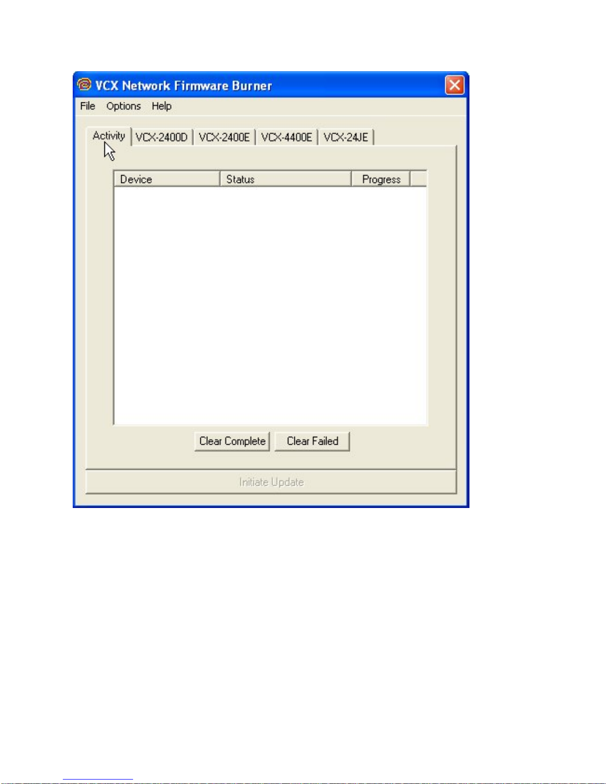
The Activity screen contains a list of the current activity and a history of past update operations.
A VCX-2400 device that has finished updating with indicate either 1) Complete, 2) Version
Current, or 3) Failed. The Device column lists the serial number of each unit that is responding
to the update command.
Page 11

NOTE: It is important that a VCX-2400 device that has a Failed status NOT be turned off or
rebooted. At the point that the failure occurs the device will not be in a bootable state. If power is
cycled or the firmware cannot be updated without failure after repeated attempts then the
firmware chip will need to be replaced. The 10Mbps revision 2.5 devices (in current production)
have removable chips that can be replaced in the field. The 100Mbps revision 3.0 devices must
be reprogrammed at the factory. Since revision 3.0 is not yet in production there may be other
safeguards, such as automatic firmware backup that may modify these instructions.
When a device is in the process of upgrading, the Activity screen will show the progress as a
percent of complete for each stage. There are four stages.. 1) Erasing, 2) Startup Code, 3)
Application Code, and 4) FPGA. When erasing the progress may not update but erasure will
compete in a few seconds. The startup code frequently completes so quickly that you don’t see it
in the Status column.
After the FPGA status reaches completion you should see the Status column change to
Complete. If it changes to Failed at any time during the firmware update you will need to retry
updating the firmware for that unit before cycling power or rebooting.
The Clear Complete button will clear the list display of any operations that did not fail. The
Clear Failed button will clear the list display of any failed operations. The Initiate Update will
Broadcast a command to all online units to connect to the update server to perform a firmware
update. Normally the update server will be the computer that is running VcxNetBurner. However
it would be possible to have VCX-2400 devices configured to use a different server. When
Initiate Update is pressed, all of the VCX-2400 devices within range of multicast packets will
connect to its preset update server.
VCX2400D Screen
The VCX2400D is accessed through the VCX-2400D tab and displays the parameters used to
select the version of the firmware sent to VCX-2400 decoder devices. This information is
imported from a import.ini file that is provided with each firmware update. This screen allows
the operator to see what update is selected. It is important to confirm that the files indicated in
the file selection boxes are located on your computer. The import file is selected using the
Page 12
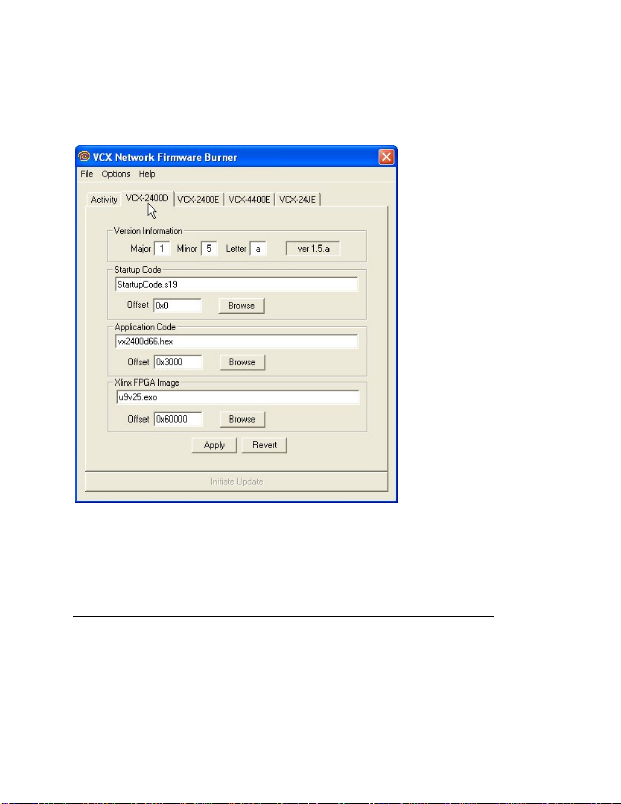
menu’s File- >Import option. This is explained later in this document. The Apply button saves
the current setting on this screen so that when VcxNetBurner is loaded these parameters are
restored. The Revert button will reload the currently saved parameter set. So if you have
modified this screen it can be restored if you haven’t used apply.
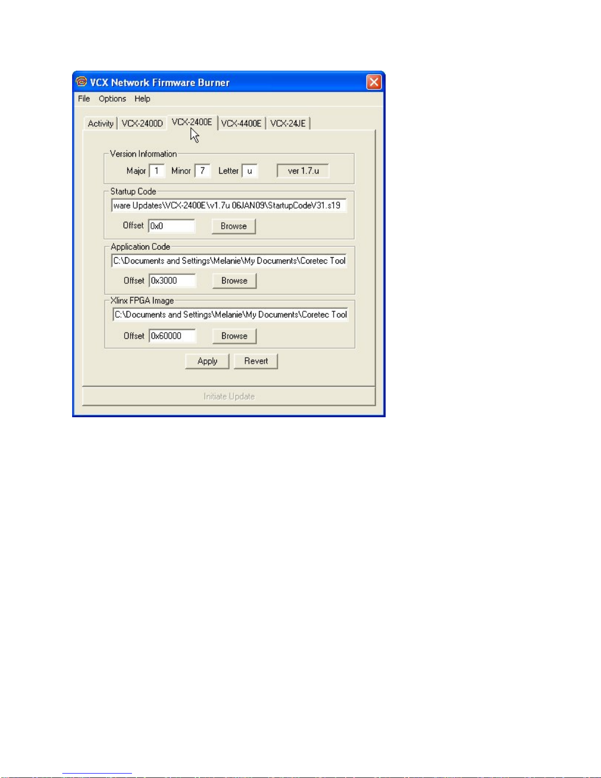
The Encoder Screens- VCX2400E, VCX440E, & VCX6400E (2/4/J-E)
The Encoder screens are accessed through the VCX2400E, VCX440E, & 2/4/J-E tabs and work
identically the same as the VCX-2400D, except that the parameters are applied to the firmware
sent to the VCX-2400, 4400, or 2/4/J Encoder devices.
Page 13
Page 14

Page 15

The Menu
File Menu
The menu contains selections for 1) File, 2) Options, and 3) Help. The File menu selection
presents the following drop down menu:
The Exit option will close the application. The Import selection is used to select and configure
VcxNetBurner for a particular firmware update version. Each firmware update will come with an
import.ini file that contains the necessary information and is accessed though the Import menu
selection. The import files are normally separate for both the decoder and encoder, and the
supplied updates should each be stored in a unique directory so that the various update files are
not overwritten. When the operator selects Import, a file selection dialog will be presented. The
operator should navigate to the directory were the firmware update is located and the import.ini
file well be selected by default as shown in the following picture:
After pressing the Open button the following dialog will be displayed.
Page 16

This dialog is telling you that you can save the imported parameters by pressing OK. Or by
pressing Cancel just use the parameters until the application is closed. If you press Cancel the
parameters are still loaded but the old parameters will be loaded then next time VcxNetBurner is
used. Selecting OK is the same as selecting Cancel and then Apply.
NOTE: If you have both encoder and decoder devices you will need to perform the Import
operation twice. One import should be performed for each type of device.
Options Menu
The Options menu selection will provide the following dropdown menu.
There are five selections in the Options menu… 1) Ignore Version, 2) Broadcast Server, 3) Lock
Update 4) Perform Packet Test & 5) Write CTC File.
The Ignore Version selection toggles between on and off. It normally should not be checked. It
will cause a device to update using the current parameters regardless of the current version. It
can be used to change a device to an older version, or even re-update the current version.
Devices will normally update only if the current device firmware version is less than the version
listed in VcxNetBurner. For example if the current device firmware version is 1.5a and the new
version is 1.5a or below, an update command will return the status “Version Current”. See the
Activity screen in this document for an example. If the Ignore Version selection is checked then
you will never get a “Version Current” status.
The second option is Broadcast Server. When the operator makes this selection it causes
Page 17

VcxNetBurner to multicast a command to all devices to set their Update Server IP to the
computer running VcxNetBurner. The devices will only remember the Update Server IP until the
next reboot or power cycle. Reboots automatically occur after a successful firmware update. It is
not necessary to perform a Broadcast Server operation if the devices have already been
programmed with an Update Server IP. This can be done with Telnet using the command:
UPDATEIP xxx.xxx.xxx.xxx
It is also possible to configure a device to use a hostname (or URL) to address the server if a
DNS server is also configured. The following are example Telnet commands for this operation.
UPDATENAME www.myupdateserver.com
DNSIP xxx.xxx.xxx.xxx
However, unless you have specific reasons for setting up your update server in the device, the
Broadcast Server command will suffice for updating your VCX-2400 device.
The Lock Update allows you to update all VCX-Devices of one type (i.e.- all VCX-2400E
connected to the network) simultaneously. We do not recommend this if you are just beginning
to use the software, due to the risk of overlooking a failure of one particular device.
Rather than this, it is suggested to update only one device at a time. This is done by following the
first 6 steps of the instructions listed above and then Telnet into the unit you wish to update and
issue the following command:
UPDATEFIRMWARE
OR
UF
You should monitor the Activity screen for progress. The Telnet session will also provide some
text display that indicates completion. If the operation is successful then the device will
automatically reboot and the Telnet session will be dropped. If the operation failed then you
should retry the UPDATEFIRMWARE command.
TIPS: If using Telnet, use the DISPLAY IP command to verify that an update server IP is listed.
Also ensure that the update server IP is reachable. This would be true if the update server is the
same as the computer in the Telnet session.
The Perform Packet Tests tests to see if the firmware can be downloaded successfully without
actually being burnt into the unit.
The Write CTC File is for Coretecs internal use only.
Help Menu
Page 18

The Help menu selection will present the following dropdown menu.
At this time the only option is the About box selection. The about box will display the current
version of VcxNetConfigure. The current version in this example is V1.1 as shown.
Instructions for Use
The following steps should be performed to update your VCX-2400 devices.
1) Obtain the latest update from Core Tec Communications.
2) Place the updates into unique directories for each the decoder and encoder. The
updates will be provided on the FTP server in separate directories.
3) Use the Import menu command to load each update’s import.ini file and use the OK
button to save the current setting.
4) Go to both the Encoder and Decoder screens and verify that the file directories and
version match the latest desired update.
5) Select the Activity screen so that the update process status can be viewed.
6) Use the menu option Options->Broadcast Server to set the current update server to
your computer (optional if configured in the devices).
7) Press the Initiate Update button to multicast the update command to all devices.
8) Monitor the update process on the Activity screen to verify that all units have updated
successfully.
IPConfiguration
Overview
The commands contained in this section provide the means to configure critical network,
com ports, encoder, and decoder parameters. The user should consult the factory if specific
functions of interest do not appear to be supported.
Page 19

InitialIPAddressing
To set the device parameters properly, encoder and decoder units must be given appropriate
IP addresses, compatible with the network on which they are to be connected. The software
module VXNETCONFIG was developed to allow a network administrator to set the IP and
Subnet in the VCX-4400 series encoders and decoders.
1) Installation
To load VXNETCONFIG insert the CORE TEC CD into your CD drive. Select
VXNETCONFIG by double clicking on the program. The following window will open:
VCXNETCONFIG Window
Page 20

Description of Program Functions
(a) The first box on the left hand side of the window displays the current IP address
of the CORE TEC device being interrogated. Type the new IP address into this
space
(b) The second box is used to change the SUBNET address. Note that the address
displayed is always 255.255.255.0. Type the new SUBNET address into this
space.
(c) The Enable DHCP box is checked when DHCP is to be enabled.
NOTE: Do not enable DHCP if sub-channels are being used of if there is no
DHCP server. Check with the Network Administrator, or call Core Tec
Tech Support if further assistance is needed.
(d) The Configure button is to execute the requested changes to the IP and SUBNET
information. Note that future queries of the SUBNET will indicate
255.255.255.0. Therefore, the correct SUBNET address should always be entered
prior to using the Configure button.
(e) The box on the right hand of the window displays all VCX-4400 devices
(encoders and decoders) on the network.
1) To make a change to the equipment addressing perform the following steps:
(a) Select the Core Tec device address from the list in the box on the right side of the
window.
(b) Move the cursor to the IP box and select the first octet by highlighting the octet.
Enter the new IP data for the selected octet. As the 3 digits are entered, the
software will automatically highlight the next octet for change. Complete
entering the IP address and then switch to the SUBNET data.
(c) Move the cursor to the SUBNET box and select the first octet by highlighting the
octet. Enter the new SUBNET data for the selected octet. As the 3 digits are
entered, the software will automatically highlight the next octet for change.
Complete entering the SUBNET data.
(d) To execute the change press the configure button. The IP address and the
SUBNET will be updated in the selected Core Tec equipment. The new IP
address will be displayed. The SUBNET will display a default class C- SUBNET
there is no read back of the changed SUBNET displayed.
(e) Repeat this process for all the CORE TEC equipment requiring change.
Page 21

ConnectingtoUnit
There are currently three ways to connect to the VCX-4400-E.
1) Telnet
Password: admin (default)
To change the default password perform the following:
Type: PASSWORD <followed by your password (up to 11 characters)>
Where <your password> equals the new password.
For configuration using an Ethernet connection, activate the Telnet function by the
following:
a. Initiating from the Command Prompt - Telnet nnn.nnn.nnn.nnn
b. Use the MS Windows – START – RUN Telnet nnn.nnn.nnn.nnn
(where nnn.nnn.nnn.nnn is the IP address of the unit being configured)
Employ the command set as described below.
Note that the initial IP addresses (factory default) are:
Encoder 192.168.0.253
Decoder 192.168.0.254
Sub net Mask 255.255.255.0
(Alternatively, the end user software SW-2400 is usable when an Ethernet connection is
established.)
Page 22

2) Terminal Program
NOTE: The following procedure is valid for standalone units only and is not applicable to
rack mount units.
The Terminal Program, such as HyperTerminal, configuration procedure uses the serial
connection on the front of the unit.
Using the PCA-2400 programming cable, connect to the control port. This cable should be
attached to the serial port of an attached PC and the Hyper Terminal program launched. The
PC should have its Com Port configured as:
Baud rate 38,400 kbps
Data bits 8 bits
Parity No Parity
Stop Bits 1 Stop Bit
Flow control None
Activate the HyperTerminal function, normally found in a sub-menu under ACCESSORIES.
Employ the command set as described in the following section.
Password: admin (default)
To change the default password perform the following:
Type: PASSWORD <followed by your password (up to 11 characters)>
Where <your password> equals the new password
3) Core Tec Watchdog Lite Software
Please refer to the Watchdog Manuals.
Page 23

ProgramCommands
IMPORTANT NOTES:
1. After entering one or more commands, it is necessary to enter COMMIT and REBOOT for
the new settings to take effect.
2. Typing “?” displays a listing of all commands.
NetworkSetup
IP (IP Address)
The IP address setup is in the form of decimal dotted notation. The selection of an IP should
come from the person who administrates the network. The current IP selection is static. A dynamic IP
setting using DHCP is planned for future enhancement.
Default:
Encoder - 192.168.0.253
Decoder - 192.168.0.254
Example command:
IP192.168.0.10 (sets IP address to 192.168.0.10)
IPMASK (IP Subnet Mask)
The IP Subnet Mask is in the form of decimal dotted notation. The selection of an IP subnet
mask should come from the network administrator. It is used to represent the number of bits in the
current IP subnet.
Default: 255.255.255.0
Example command:
IPMASK255.255.240.0
GATEWAY <ip-address> [<ip-subnet address> <subnet mask>]
The GATEWAY command can have either one or three parameters. The first parameter is th e IP
address of the host that is the gateway. Optionally you may include the IP address and the subnet mask of
the subnet you want to route through the gateway. You can program up to five gateway entries.
Default: No Gateways
Example command:
GATEWAY192.168.0.1
The following example indicates that all packets sent to hosts on the 62.41.1.0.xxx subnet should be
routed though the gateway at 192.168.0.2
Example command:
GATEWAY192.168.0.262.41.1.0255.255.255.0
CLEARGATEWAY
Page 24

This command will clear the gateway table. There are no parameters. This command clears all
entries.
CMDPORT <TCP command port number>
The TCP command port selection is configurable. However, the default setting should be
adequate for normal operation. The command port is used by software that can operate the VCX-4400
devices programmatically. For example, a Microsoft Windows GUI based application.
Default: 5000
Example Command:
CMDPORT<sp>5010 (sets TCP command port to 5010)
VIDEOIP <video destination IP address>
The video destination IP is an address that allows the reception of the MPEG-4 stream by a single
(unicast) or multiple (multicast) device(s).
NOTE: Class D IP addresses, in the range 224.0.0.0 to 239.255.255.255 are called multicast addresses.
The range 224.0.0.0 to 224.0.0.255 is reserved for local purposes and the range 239.0.0.0 to
239.255.255.255 is reserved for administrative scooping. Both the encoder and decoder should be set to
the same Video IP for correct operation together.
Default: 239.5.6.8
Example Command:
VIDEOIP234.5.6.10 (sets multicast IP to 234.5.6.10)
VIDEOPORT <video multicast port number>
The video multicast port selection is configurable. However, the default setting should be
adequate for normal operation.
Default: 4568
Example Command:
VIDEOPORT4569 (sets multicast port to 4569)
CommonCommands
The following commands apply to both encoders and decoders.
COMMIT
This command saves the parameter changes in permanent memory. A commit command must be
issued before a reboot or power cycle if the new device settings are to be maintained.
DEATHBLOW
This command causes a reboot of the device. The purpose of this command is to cause a reboot
from the password prompt. If you cannot login into the command, prompt because of the “Another
administrator is logged in.” message, then you can use DEATHBLOW as the password to return the unit
to the power up state.
Page 25

EXIT
Exits from the command prompt and rel eases the current login. You may also use the following
alternatives… LO (Log Off) and QUIT.
NTSC
This command sets unit for NTSC video operation.
PAL
This command sets unit for PAL video operation.
REBOOT
This command restarts device from power-up state. Most changes in device settings require a
reboot after a commit.
START
This command starts encoding or playback (video out).
STOP
This command stops encoding or playback (video out).
VER
This command displays the software version/build date, BSP (board support package)
version/build date, and board revision.
Example response:
Version: VCX2400d3 v1.6a, Date: 29JUN04
BSP VCXV73 v1.2, 04JUN04
Board revision: 3.1
EncoderCommands
These commands are associated with the encoder functions of the unit. There are two video input
ports that may be multiplexed to any of the three encoder channels. The MPEG2, MPEG4 and JPEG
functions which are separate hardware and software are in fact separate channels with in the unit.
VIDEOIN <1|2>
This command selects the video input channel to be addressed by all the other commands. Valid
options are 1 or 2. Note this command is valid on models with dual video BNC connectors.
Example videoin 1 (the currently selected encoder will receive the video stream
from channel 1 connector)
COMPortSetup
The VCX-4400 supports two sub-channels that allow the two-way transmission of serial data to
selected target devices. The sub-channel can be configured for either RS232 or RS422 operation. It is
Page 26

not necessary for both ends to use the same configuration. The following is a list of the configuration
items for the sub-channel:
Channel Enable
Baud rate
Parity
IP address of target
TCP port for operation
RS422 or RS232
Certain VCX-4400 devices can be delivered with either one or two com ports. The ports are designated
as 1 and 2. The commands for configuring the settings use the A or B designation to indicate the port
being configured.
Example(s): COM1xxx for com port 1 (selects com port 1)
COM2xxx for com port 2 (selects com port 2)
Note: Communications port 2 is also the control port for programming. If this port is also needed for
non-programming related data purposes, the user should program the necessary parameters with the
jumper in place if using the Hyper Terminal method. Upon completion of programming, removal of the
jumper will result in port 2 operating as programmed. If not using Hyper Terminal to program, jumper
should be removed if com port 2 is to be used.
COM1, COM2 (0|1)
This command sets the active state of the com port. The parameter is “0” or “1”, where “1”
enables and “0” disables the com port function. At this time, the com port is always enabled and this
command has no effect.
Default: 0 (OFF)
Example Commands: COM11 (enables com port 1)
COM1BAUD, COM2BAUD (Comm Port Baud Rate)
This command sets the baud rate for the comm port. Valid values are 2400, 4800, 9600, 19200,
and 38400. Other data rates may be functional but are not tested.
Default: 9600
Example Command: COM1BAUD4800
(sets baud rate for com port 1 at 4800 bps)
COM1PARITY, COM2PARITY (Com Port Parity)
The parity for the com port can be set to Odd, Even, or None. The parameters for the
COM[1|2]PARITY command are N,O,E, which correspond respectively to None, Odd, Even.
Default: None
Example Command: COM2PARITYN (sets com port 2 to no parity)
COM1IP, COM2IP (Com Port IP)
Page 27

The IP address of the destination for the com port data is set by this command. A typical setup
would have an encoder and a decoder. The decoder would have a com port IP address that is the same as
the encoder. In addition, likewise, the encoder’s com port IP would be the same as the decoder. Notice
that the default com ports IP’s are the opposite of the default device IP’s.
Default:
Encoder com ports - 192.168.0.253
Decoder com ports- 192.168.0.254
Example Command: COM2IP 192.168.0.10 (points the com port data to an encoder,
decoder, or other device whose IP address is 192.168.0.10)
COM1PORT, COM2PORT (Com Port)
The com port selection is configurable. However, the default setting should be adequate for normal
operation.
Default:
Com port 1 - 5002
Com port 2 – 5004
Example Command: COM1PORT5010 (sets com port 1 to port 5010)
COM1RS422, COM2RS422 <0|1>
The com port data-format is configurable. The parameter is “0” or “1”, where “1” enables RS-422
and “0” enables RS-232 format.
Default: 0 (RS-232)
Example Command: COM1RS4220 (sets com port 1 for RS-232)
COMM PORT COMMAND – FURTHER EXAMPLES
The following examples set up com port 1:
COM11 – Enable com port 1
COM1BAUD9600 – Set com port 1 baud rate to 9600
COM1RS4221 – Set com port 1 mode to RS422
COM1PORT5002 – Set com port 1 port to 5002
COM1PARITYE – Set com port 1 parity to even
COM1IP192.168.0.10 – Set destination address for data to 192.168.0.10
COMxTCP<0|1>
1= Use TCP, 0=Use UDP
COMxSERVER<0|1>
1 = server, 0 = client
Page 28

OSDCOMMANDS(OnScreenDisplay)
These permit the configuration of the On-Screen-Display(OSD) properties of the encoder. This
section is for labeling the video stream.
OSD <1…5> <label text>
This command permits up to five lines of text to be configured for display with the outgoing
video stream. The text lines must be assigned from 1 to 5 in order and unassigned lines between assigned
lines are not permitted. All five lines need not be assigned text strings.
Example
osd 1 This is the first line of text.
osd 2 This is the second.
This is the first line of text.
This is the second
OSDX <1…5> <x pos>
This command will locate the line of text associated with the number 1-5 with the horizontal
location defined by the <x pos>.
Example
osdx 1 50 will set the first character of the line of text 1 to x position 50.
OSDY <1…5> <y pos>
This command will locate the line of text associated with the number 1-5 with the horizontal
location defined by the <y pos>.
Example
osdy 1 50 will set the first character of the line of text 1 to y position 50.
Note:When using the OSDX and OSDY commands, the screen resolution must be taken into account.
Locating the first character outside the video frame will prevent that entire line from being displayed. If
the first character is within the field but the string is longer that the video frame the string will wrap
around and the line directly below will not be displayed. Characters are 16x16 pixels and relate to the
current resolution set by the “PROFILE” command. The range of coordinates starts with 0 and continue
to the maximum pixel range divided by 16 (character size) and subtract 1 ( because 0 is the first position).
Example
D1 resolution in the vertical (Y direction) is 480 and yields 30 line locations
(480/16)-1=29 so line 0 to line 29 are the available Y locations.
OSDCLEAR
This command will clear all the fields configured by the previous commands.
VideoCommands
These are associated with the quality of video being encoded. The resolution both in frame size
and in the time domain are supported in this command set.
STREAMTYPE
This command selects between Program and Transport multiplexing of the video stream.
Acceptable parameters are T or P, where P is Program and T is Transport.
Page 29

Default: P (program stream)
Example: STREAMTYPE T (transport stream)
PROFILE
This command is used to select a desired resolution for the encoded video. It also sets the
optimal defaults for other parameters, such as bit rate. The allowable settings are QQCIF, QCIF, CIF,
1/2, D1.
Default: 1/2
Example Command: PROFILE1/2 (sets resolution to 1/2 D1)
Note: Since the Profile command selects defaults for other settings, it should be issued before any other
commands relating to the encoded MPEG stream.
QQCIF 80x60
QCIF 160x120
CIF 352x240
1/2 352x480
D1 720x480
FPS [n]
Sets encoded frames/second. Where n = frames per second of the video stream (i.e. 30, 15, 10, 5,
3, 2, 1)
GROUPLEN[n]
Sets frame spacing between I frames. Where n = number of frames between I-Frames.
Default: 30.
A larger GROUPLEN and smaller FPS increases the startup time of the decoder.
RES <D1|2/3|1/2|SIF|QSIF|VGA|QVGA|QQVGA>
Sets encoder resolution. QSIF, VGA, QVGA, and QQVGA are not supported by MPEG2
(Encoder 1).
QQVGA - 160x120 (cropped horz)
QSIF - 176x120
QVGA - 320x240 (cropped horz)
SIF - 352x240
1/2 - 352x480
VGA - 640x480 (cropped horz)
D1 - 720x480
Page 30

BRIGHT [n]
This command adjusts image brightness. The acceptable range is from 0 to 255, where a higher
number provides more brightness.
Default: 128
Example Command: BRIGHT170 (increases brightness from default setting)
CONTRAST [n]
This command adjusts image contrast. The acceptable range is from 0 to 127, where a higher
number provides more contrast.
.
Default: 63
Example Command: CONTRAST90 (increases contrast from default)
SATURATION [n]
Adjusts color saturation. The acceptable range is from 0 (no color) to 127.
Default: 63
Example Command: SATURATION75(increases color saturation from default)
TINT [n]
Adjusts color tint. The acceptable range is from –128 to 127.
Default: 0
Example Command: TINT10 (adjusts tint)
BITRATE [n]
This command adjusts the bit rate (in kbits/sec) of the encoded MPEG-2/4/JPEG video. This sets
the maximum rate (of the variable bit stream) encoded. If audio is in the MPEG-2/4/JPEG stream, then
an additional 256 kbits/sec will be added to the rate set by this command.
Default: The default is set by the Profile command
Example Command: BITRATE2000 (Sets max bit rate to 2 Mbits/sec)
Note: This command should be issued AFTER the Profile command if the Profile command is used.
SAPSettings
The encoder is capable of multicasting SAP (Session Announcement Protocol RFC-2974) packets
with SDP (Session Description Protocol RFC-2327) content. There are a number of parameter settings
for configuring SAP. They are presented in this section. The user should refer to the referenced RFCs to
understand the significance of the SAP/SDP parameter settings.
Page 31

SAP
This command is used to enable or disable the SAP multicast. ON or OFF are the permitted
parameters.
Default: OFF
Example: SAP ON
SAPAUTHOR
This command is used to set the SDP (RFC-2327) author information. The parameter is an
ASCII string with a limitation of 30 characters.
Default: No text
SAPCOPYRIGHT
This command is used to set the SDP (RFC-2327) copyright information. The parameter is an
ASCII string with a limitation of 30 characters.
Default: No Text
SAPINFO
This command is used to set the SDP (RFC-2327) info information. The parameter is an ASCII
string with a limitation of 62 characters.
Default: Core Tec VCX2400e
Example: SAPINFO Intersection of 1st and main
SAPINTERVAL
This comman d sets the interval between SAP packet transmissions. The parameter is the number
of milliseconds between transmits.
Default: 5000 ms (5 seconds)
Example: SAPINTERVAL 10000 ms (10 seconds)
SAPIP
This command sets the IP address of the destination host for SAP packets. This address is a
multicast address defined in RFC-2974. It is unlikely that the user will need to change this setting.
Default: 224.2.127.254
SAPKEYWORD
This command is used to set the SDP (RFC-2327) keyword information. The parameter is an
ASCII string with a limitation of 30 characters.
Default: No text
SAPNAME
This command is used to set the SDP (RFC-2327) name information. The parameter is an ASCII
string with a limitation of 30 characters.
Default: Core Tec Communications, LLC
Example: SAPNAME Main Street Camera #1
Page 32

SAPPORT
This command sets the destination port for SAP packets. The port number is defined in RFC-
2974. It is unlikely that the user will need to change this setting.
Default: 9875
SAPUPDATE
Issue this command after changing the SAP parameters to update all devices listening to SAP
multicasts.
MiscellaneousSettings
CAMERA [n]
Store a user defined camera type code 0..255
This is a current list of the Cameras we support:
Cohu = 1
Philips_Bosch = 2
Pelco = 3
Vicon = 4
RVision = 5
Panasonic = 6
CAMERAID [n]
Store a user defined camera ID code 0..255
DISPLAY <VIDEO | COM | IP | SAP | MISC>
This command displays current encoder settings. Entering DISPLAY only provides all settings.
Adding the VIDEO, COM, IP, SAP, or MISC displays those respective settings specifically.
Example Command: DISPLAY IP (displays current IP encoder settings)
WD
The watchdog is a timer that will perform a complete reset of the device if the firmware encounters a
lockup condition. The parameter is “0” or “1”, where “1” enables and “0” disables the watchdog
function. Enabling the watchdog allows the VCX-4400 devices to recover from some fatal error
conditions without user intervention.
Default: 0(OFF)
Example Command: WD1 (enables watchdog)
AUTOREBOOT
Page 33

This command permits a periodic timed reboot of the device. The parameter is the number of
seconds between reboots.
Default: 0 (off)
Example: AUTOREBOOT3600
AUTOSTART
This command sets a periodic timed restart of the video encoder/decoder. The parameter is the
number of seconds between starts.
Default decoder: 0 (off)
Default encoder: 28800(8 hours)
Example: AUTOSTART3600
300 seconds equals 5 minutes
3600 seconds equals 1 hour
DATE
Example: DATE[yyyy:mm:dd]
TIME
When entering time, it needs to be typed in in 24 hour notation.
Example: TIME[hh:mm<:ss>]
JOIN VIDEO MULTICAST
Example: JVM [1|0]
1=on
0=off
Specifications
PHYSICAL AND ENVIRONMENTAL
Dimensions
11.0” x 5.25”
Mounting
R-12 Card Cage Enclosure
Weight
Page 34

.6 pounds
Temperature
-20 degrees to + 70 degrees Centigrade
(-4 to 158 degrees Fahrenheit)
Humidity
0 to 95% non-condensing
POWER REQUIREMENTS
From Enclosure
CONNECTORS
Video
NTSC/PAL BNC
Power
From Back-plane (36 pin Molex)
Data
Network RJ-45
Com ports RJ-45
ELECTRICAL
Video Input (NTSC/PAL)
Impedance: 75 ohm unbalanced, return loss > 30 dB
Dynamic
Range: 0.5 volts to 2.0 volts peak to peak
Video Output (NTSC/PAL)
Impedance: 75 ohm unbalanced, return loss >
Output Level: 1.0 volts peak to peak nominal
(.9 volts minimum to 1.1 volts maximum)
Sync Level: 257 mV (36 IRE) to 314 mV (44 IRE)
Bar Level: 642 mV (90 IRE) to 785 mV (110 IRE)
Burst Level: 257 mV (36 IRE) to 314 mV (44 IRE)
30 dB
Page 35

Resolution: Full D1: 720h x 480v (NTSC); 720h x 576v (PAL)
1/2 D1: 352h x 480v (NTSC); 480h x 576v (PAL)
CIF: 352h x 240v (NTSC); 352h x 288v (PAL)
QCIF: 160x120
QQCIF: 80x60
Frame Rate: 1 to 30 frames per second maximum
Data (Network)
Format: Ethernet IEEE 802.3; 10/100 Base T
Line Rate: down to 64kbps
Data (Sub-channels)
Format: RS-232 or RS-422 (programmable) (2)
Data Rates: 2400, 4800, 9600, 19200, 38400 bps
Programming Data
Format: EIA RS-232C (primary data lines)
Rate: 38.4 kbps
Form: 8-bit data, 1 stop bit, no parity
ModelNumbers
BASE MODELS
VCX-4400-E MPEG 4 Video Encoder – IP
VCX-4400-E-R MPEG 4 Video Encoder – IP (Card Cage Mount)
*Note: Base models feature two data sub-channels
ACCESSORIES
R-12 Card Cage Enclosure
(see R-12 data sheet for product options and accessories)
PCA-2400 Programming Cable Assembly
Page 36

SW-2400 Video Watchdog
AppendixA
Pinouts
Com Port Data Interface Pin Out(uses RJ-45 Plug)
Pin Signal Description Signal Type
1 RS-232 Receive Input
2 RS-232 RTS Output
3 RS-232 Transmit Output
4 RS-232 CTS Input
5 RS-422 Receive Data + Input
6 RS-422 Transmit Data - Output
7
8 RS-422 Transmit Data + Output
RS‐422
RS-232
Receive Data Ground
TM
User Software
Input
Ground
StandardEthernetPinOut
Straight Through Ethernet Pin Out Cross Over Ethernet Pin Out
Page 37

RJ11toSerialInterfaceAdaptorPinout
The PC should have its Com Port configured as:
Baud rate 38,400 kbps
Data bits 8 bits
Parity No Parity
Stop Bits 1 Stop Bit
Flow control None
RJ-11 Adaptor VCX-Encoder Series
Front Panel Serial Interface
5
9
4
8
3
7
2
6
1
Manufac t ur er Supplied Serial Adapt or
WHT
BLK
RED
6
5
4
3
2
1
Below is the pin layout of the RJ-11:
Pin Function
Page 38

Troubleshooting
1 Ground
2 Unused
3 Unused
4 Serial Out
5 Serial In
6 Ground
 Loading...