

Page 1

BS Controller for AC SERVO PRESS
BS Controller for AC SERVO PRESS Instruction Manual
Introduction
Request
Instruction Manual Ver1 .08
BS-M3A-1B
Thank you very much for purchasing our Servo press.
This manual describes the hardware scheme, installation procedures, connections,
running, operations, communication, status display and daily inspections.
Make sure to thoroughly understand the contents and use the product properly.
We have taken all possible measures to ensure the contents of this instruction
manual, however, please contact us if you have any questions or find any errors.
The product names, etc. are generally registered trademarks of various companies.
* To secure safety and quality, never fail to refer to this manual.
- 1 -
Page 2

BS Controller for AC SERVO PRESS
1. For safe use ................................................................................................................. 7
2. Before use .................................................................................................................. 11
3. Specifications .............................................................................................................13
4. Construction ..............................................................................................................16
5. Installation ................................................................................................................18
Instruction Manual Ver1 .08
BS-M3A-1B
Table of contents
1.1. Regarding symbols .................................................................................................. 7
1.2. Observe the following for safety ............................................................................. 7
1.3. Caution on attachment and use. .......................................................................... 8
1.4. Make sure to observe for sequencer circuit ........................................................... 9
1.5. EMC directive .......................................................................................................... 9
1.6. Others ....................................................................................................................... 9
1.7. The relation with the Mitsubishi Electric servo system ..................................... 10
2.1. Characteristics of Servo press ............................................................................... 11
2.1.1. Possible to record program execution result ................................................. 11
2.1.2. Programmable action possible ....................................................................... 11
2.1.3. Display of load and stroke during program execution and Graph display . 11
2.2. The suiting tool ....................................................................................................... 11
2.3. Accompanying items .............................................................................................. 11
2.4. About the model name and the version ............................................................... 12
2.4.1. Anybus option ................................................................................................. 12
3.1. Specifications of BS-M3A-1B ................................................................................ 13
3.2. Specifications fo brake .......................................................................................... 13
3.3. Common specification of MR-J3A ........................................................................ 14
3.4. Specification peculiar to the tool type .................................................................. 14
3.4.1. BS100 series ................................................................................................... 14
3.4.2. BS200 series ................................................................................................... 15
4.1. Name of each part of the controller ...................................................................... 16
4.2. Outline .................................................................................................................... 17
4.3. Connection figure (include options) ..................................................................... 18
5.1. Procedures for installing to control panel ............................................................ 20
5.1.1. Designing conditions for control box ............................................................. 20
5.1.2. Cautions when installing BS ......................................................................... 20
- 2 -
Page 3

BS Controller for AC SERVO PRESS
6. Installing lines ...........................................................................................................21
7. Timing Chart .............................................................................................................31
8. Concept of stroke .......................................................................................................36
Instruction Manual Ver1 .08
BS-M3A-1B
5.1.3. The interval with MR-J3A ............................................................................. 20
5.1.4. Noise Filter of MR-J3A .................................................................................. 20
6.1. Load cell i/f(CN31) ................................................................................................. 21
6.2. Origin sensor i/f(CN32) ......................................................................................... 21
6.3. MR-J3A parallel i/f(CN33) .................................................................................... 21
6.4. Emergency stop(CN34) ......................................................................................... 21
6.5. RS-232C(CN4) ....................................................................................................... 22
6.6. RS-232C(CN5) ....................................................................................................... 22
6.7. RS-485(CN6,7) ....................................................................................................... 22
6.8. Ethernet(CN8) ....................................................................................................... 23
6.9. Parallel I/O (CN9) .................................................................................................. 23
6.9.1. Bit assignment ............................................................................................... 24
6.9.2. PIO connector pin assignment ...................................................................... 27
6.9.3. Wiring by the side of input ............................................................................ 27
6.9.4. Wiring by the side of output .......................................................................... 28
6.10. Control power supply (CN10) ........................................................................... 28
6.11. Backup battery(CN11) ...................................................................................... 28
6.12. Anybus .................................................................................................................... 28
6.13. Brake ...................................................................................................................... 29
6.14. Motor cable ............................................................................................................. 30
6.15. Encoder Cable ........................................................................................................ 30
7.1. Power supply injection .......................................................................................... 31
7.2. Alarm reset ............................................................................................................ 31
7.3. Origin ..................................................................................................................... 31
7.4. JOG ......................................................................................................................... 32
7.5. Program execution ................................................................................................. 32
7.6. Program execution using Post Judge ................................................................... 33
7.7. Writing of a product name and a serial number ................................................. 34
7.8. Post Judge .............................................................................................................. 35
8.1. Semi closed loop ..................................................................................................... 36
8.2. Direction ................................................................................................................. 36
- 3 -
Page 4

BS Controller for AC SERVO PRESS
9. Connection with Personal Computer ........................................................................38
10. Starting ..................................................................................................................44
Instruction Manual Ver1 .08
BS-M3A-1B
8.3. System home position ........................................................................................... 36
8.4. User home position ................................................................................................ 36
8.5. System stroke limit ............................................................................................... 36
8.6. User stroke limit .................................................................................................... 36
8.7. If the stroke limit is exceeded ............................................................................... 37
8.8. A motion of the ram at the time of servo off ........................................................ 37
9.1. Spindle number setup ........................................................................................... 38
9.2. IP address setup of BS controller ......................................................................... 38
9.3. IP address setup of a personal computer ............................................................. 38
9.4. LAN cable ............................................................................................................... 39
9.5. Communicative check ........................................................................................... 39
9.5.1. Setup of operational authoority .................................................................... 39
9.5.2. Setup of receive filter ..................................................................................... 40
9.5.3. Collection setup .............................................................................................. 40
9.5.4. Check of status ............................................................................................... 40
9.6. Starting of two Configurators ............................................................................... 41
9.7. Use of two or more network interface cards ........................................................ 42
9.8. Arbitrary IP address setup ................................................................................... 42
9.8.1. Notes ............................................................................................................... 42
9.8.2. The communication method with an IP address unknown controller ....... 43
10.1. Starting procedure of BS controller ..................................................................... 44
10.1.1. Attachment to equipment .............................................................................. 44
10.1.2. Wiring .............................................................................................................. 44
10.1.3. Control power supply injection ..................................................................... 44
10.1.4. Attachment of a backup battery ................................................................... 44
10.1.5. Parameter setup of MR-J3A .......................................................................... 44
10.1.6. Parameter setup of BS ................................................................................... 44
10.1.7. Re-starting of a power supply ....................................................................... 44
10.1.8. Check of a brake ............................................................................................. 44
10.1.9. Check of an emergency stop .......................................................................... 44
10.1.10. Origin .......................................................................................................... 44
10.1.11. Build a program. ......................................................................................... 44
10.1.12. Execution of a program .............................................................................. 45
- 4 -
Page 5

BS Controller for AC SERVO PRESS
11. Troubleshooting .....................................................................................................53
12. Regeneration ..........................................................................................................61
13. Absolute encoder system ........................................................................................62
14. Load-Sensor-less System .......................................................................................63
15. Tool Type Discernment ..........................................................................................64
16. Stole .......................................................................................................................65
17. Others ....................................................................................................................66
18. Article of Consumption ..........................................................................................67
Instruction Manual Ver1 .08
BS-M3A-1B
10.2. Parameter setup of MR-J3A ................................................................................. 45
10.3. Parameter setup of BS controller ......................................................................... 49
10.4. Re-injection of a control power supply ................................................................. 50
10.5. Check of the brake ................................................................................................. 50
10.6. Check of emergency stop ....................................................................................... 51
10.7. Origin ..................................................................................................................... 51
10.8. Program creation ................................................................................................... 51
10.9. Execution of a program ......................................................................................... 52
11.1. The state display by LED ..................................................................................... 53
11.2. Alarm code table .................................................................................................... 54
12.1. Lowering regeneration frequency ........................................................................ 61
12.2. Regeneration option .............................................................................................. 61
13.1. Setup....................................................................................................................... 62
13.1.1. Setup to BS controller .................................................................................... 62
13.1.2. Setup to MR-J3A ............................................................................................ 62
13.1.3. Wearing of a backup battery ......................................................................... 62
13.2. The alarm release method .................................................................................... 62
17.1. The options of the servo press .............................................................................. 66
18.1. Battery ................................................................................................................... 67
18.1.1. The detection method ..................................................................................... 67
18.1.2. The exchange method .................................................................................... 67
18.1.3. Management ................................................................................................... 67
18.1.4. Clock setup ..................................................................................................... 67
- 5 -
Page 6

BS Controller for AC SERVO PRESS
19. Maintenance of Tool ...............................................................................................68
20. Cautions on abandonment .....................................................................................68
Instruction Manual Ver1 .08
BS-M3A-1B
18.2. Parts having service lives of MR-J3A .................................................................. 67
- 6 -
Page 7
BS Controller for AC SERVO PRESS
1. For safe use
1.1. Regarding symbols
1.2.
Observe the following for safety
This symbol assumes the possibility that accidental
death or serious injury may occur immediately to the
user, if the symbol is neglected and the product is
incorrectly handled.
The power source is as high as 200V. Look out for electric shock.
This symbol assumes that there is a potential for
personal death or injury if this expression is ignored
and this product is mishandled.
In a case where the product is used in an application in which an accident resulting in
as installing a fail-safe device.
Do not use around combustible gas. If disregarded, it may lead to an explosion.
In a case of handling cables and connectors, etc., cut off the power temporarily without fail.
If disregarded, it may lead to an electric shock.
Do not remove the cover, disassemble, repair or modify the product. If disregarded, it may
lead to an electric shock.
Make sure to connect the protection conductor terminal to ground.
Electric shock might be caused.
Do not touch the power supply terminal in this equipment within five seconds after the
power is turned off. It could cause the electric shock.
Do not forcibly twist, pull or scratch the power cord or cord of the AC plug.
DANGER
WARNING
Instruction Manual Ver1 .08
BS-M3A-1B
Symbols are used to provide warnings in this instruction manual and for indication for
proper product use and to prevent danger to the user or other people and damage to
property from occurring. Understand the indication meanings before reading this
manual.
death or injury or a serious expansion of damage is predictable, take safety measures such
- 7 -
Page 8
BS Controller for AC SERVO PRESS
This symbol assumes that there is a potential for
personal death or injury if this expression is ignored
and this product is mishandled.
Please use this product under the environment of overvoltage category II specified in IEC
60664-1.
Please use this product under the environment of Pollution Degree II specified in IEC
60664-1.
For the operation, stop, and emergency stop shall be done in the final machinery into which
this equipment is incorporated.
This product will surely be in a servo off state, when it is in an alarm state. However,
battery alarm is excepted.
Set up the emergency stop and interlock circuit with the external circuit.
This allows to prevent expansion of damage.
Use the input voltage, frequency and output voltage, and current within the standard. If
disregarded, it may lead to an accident or electric shock.
Do not use the product at over the specified ambient temperature. If disregarded, it may
lead to fire or electric shock.
Use in an environment without condensation due to water or moisture. If disregarded, it
may lead to an electric shock.
When output cannot be obtained, or any other abnormality is found during operation, stop
the product or our company’s sales office without fail.
1.3.
Caution on attachment and use.
This symbol assumes that there is a potential for
personal death or injury if this expression is ignored
and this product is mishandled.
Installation, connection, driving and operation, check and failure diagnosis shall be done by
a qualified technician.
Do not move, install, connect and check this equipment while the power is on. Please make
sure the power is turned off for conducting these works.
For installation requirements of this equipment, protection against electric shock is class
sure this equipment is grounded when installed. (PE should be marked at the protective
earthing terminal.)
This equipment shall be stored in a dustproof and drip-proof controlled box. (IP54 class) If
proof is not strong enough, dielectric strength shall
be decreased, and the potential of dielectric breakdown shall be increased.
The cross-sectional area of the protective bonding conductor shall be the same size as the
input power wire for this equipment.
Do not tighten the Servo press control cable excessively with binding band. Malfunction
might be caused.
The electric shock protection from the power supply terminal block of this equipment to
final machinery shall be provided in the final machinery.
For 24 VDC power supply, use SELV power supply which comply with IEC standard.
A breaker that comply with IEC Standard shall be installed in the final machinery into
which this equipment is incorporated,for the short-circuit protection of this equipment.
The methods of the ground fault protection of this equipment are as follows:
b) For the TN grounded system: Use an over current breaker generally. (The fault loop
CAUTION
WARNING
Instruction Manual Ver1 .08
BS-M3A-1B
use immediately. It may lead to electric shock. Contact the distributor where you purchased
Ⅰ,and equipment mobility is a stationery equipment for indoor installation. Please make
the performance of dustproof and drip-
a) For the TT grounded system: Use an earth leakage breaker (Type A or B shall be used)
- 8 -
Page 9
BS Controller for AC SERVO PRESS
impedance in the final equipment shall satisfy the overcurrent characteristics of the
This symbol assumes that there is a potential for
personal death or injury if this expression is ignored
and this product is mishandled.
When attaching the CPS body, allow a space of 25 mm or more for the right and left
directions and 80 mm or more for up and down directions for cooling.
Do not apply more load on the Servo press tool than allowed.
The life might be considerably shortened.
For connection to the protective earthing terminal, one wire should be provided for each
terminal.
The insulation’s color of the protective earthing conductor shall be green-and-yellow.
Design the sequencer circuit under consideration of safety measure such as emergency stop.
1.4.
Make sure to observe for sequencer circuit
This symbol assumes that there is a potential for
personal death or injury if this expression is ignored
and this product is mishandled.
Insert or pull off the connector only after turning off the power.
Otherwise, controller might fail.
Improper understanding of stroke might cause serious accident. Please understand the
Section 8 in this manual to handle.
1.5.
EMC directive
1.6.
Others
WARNING
CAUTION
Instruction Manual Ver1 .08
BS-M3A-1B
breaker so that the breaker shall be interrupted within 0.4s or less when earth fault is
occurred.)
Safety measure
The EMC directive applies not to the servo units alone but to servo-incorporated
machines and equipment.
This requires the EMC filters to be used with the servo-incorporated machines and
equipment to comply with the EMC directive.
Please ask a concrete solution to our office.
This equipment is classified into the partly completed equipment according to
Machinery Directive (2006/42/EC). Therefore, after this equipment is incorporated into
the final machinery, conformity with Machinery Directive (2006/42/EC) shall be needed
in the final machinery.
- 9 -
Page 10

BS Controller for AC SERVO PRESS
1.7. The relation with the Mitsubishi Electric servo system
Instruction Manual Ver1 .08
BS-M3A-1B
CE marking based on Machinery Directive is not done to the partly completed
machinery. Therefore, for the case that circulates by the partly completed machinery
until this equipment is incorporater into the final machinery in Europe. It is necessary
for the declaration of incorporation and the manual of this equipment to be appended to
this equipment
BS controller works as a higher rank controller of Mitsubishi Electric servo system
MR-J3A.
Please refer to the manual of the Mitsubishi Electric issue about the details of a
MR-J3A system.
- 10 -
Page 11

BS Controller for AC SERVO PRESS
2. Before use
2.1. Characteristics of Servo press
2.1.1. Possible to record program execution result
2.1.2. Programmable action possible
2.1.3. Display of load and stroke during program execution and Graph display
2.2. The suiting tool
Tool type
Adaptation load
(kN)
Servo amplifier
Motor
BS100 series
100
MR-J3-500A
HC-RP503(B)K
BS200 series
200
MR-J3-700A
HF-SP702(B)K
2.3. Accompanying items
Instruction Manual Ver1 .08
BS-M3A-1B
The Servo press provides new production controls, press methods and other actions
by programmable operations, controls and monitoring of the load and stroke
amount. The characteristics are given below.
Up to 2700 pieces of data of press results can be recorded inside the BS
Controller.
By using communications software, infinite data can be recorded.
Among factors such as speed, load stroke, time and communications with
external I/O, the programmable factor is what primarily concerns the
customer.
(Refer to the BS Configurator Instruction Manual)
By using special communications software, the values of load and stroke can
be monitored. The electric current can also be monitored by selecting the
details screen. A graph can be displayed after actions and detailed
information can be obtained.
Big-sized servo press controller BS-M3A works as a higher rank controller of
Mitsubishi Electric servo amplifier MR-J3A. The combination of servo amplifier
and a motor is decided according to the adaptation load of a tool.
BS-M3A-1B main body
A set of plug for CN34 (EMERGENCY)
Maker:Phoenix contact Model:MC1.5/2-STF-3.81
A set of plug for CN10 (DC power supply)
- 11 -
Page 12

BS Controller for AC SERVO PRESS
2.4.
About the model name and the version
2.4.1. Anybus option
Code
None
No Anybus option,PIO
CC
CC-Link
DV
DeviceNet
PF
Profibus DP
EI
EtherNet/IP
PN
PROFINET I/O
Instruction Manual Ver1 .08
BS-M3A-1B
Maker:Phoenix contact Model:MC1.5/3-STF-3.81
Backup battery(CR2032WK13)
Operating manual(CD-R)
MR-J3A
The characters which follow the basic model name are explained. At
BS-M3A-1B-zz, zz expresses Anybus option.
説明
- 12 -
Page 13

BS Controller for AC SERVO PRESS
3. Specifications
3.1. Specifications of BS-M3A-1B
Items
Contents
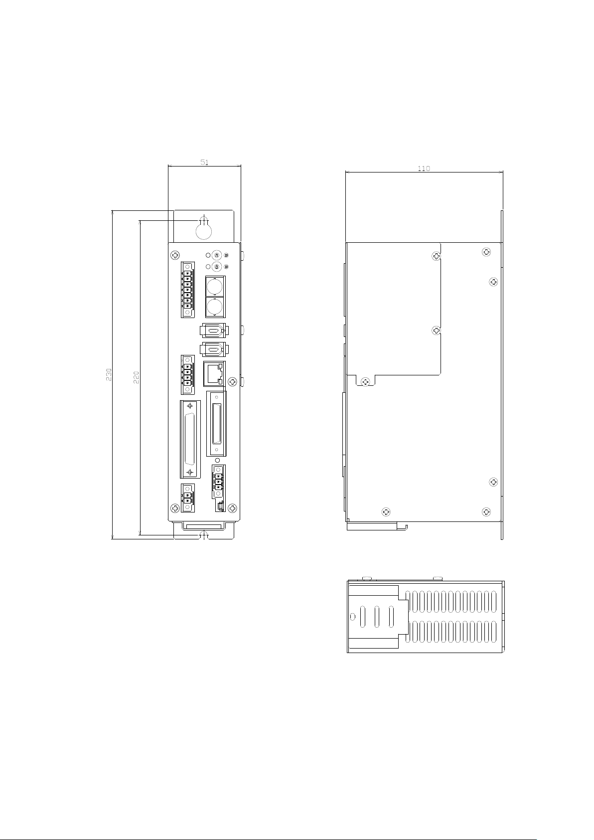
Outline
Refer to outline diagram on the Appendix(Section 4
Environ
ment
Temperature
0~50℃
Humidity
85% or less (No condensation)
Altitude
Altitude 1000 m or lower
Installing
location
Harmful places with corrosive gas, cutting oil, metal powder, oil
etc., are not allowed.
Power for control
DC24V±10%
Power consumption [W]
6 *1
Installing procedures
Installing on back panel
Vibration proof
0.5G(10~50Hz)
Shock proof
5G
Serial communications
RS-485
115.2kbps occupied by MR-J3A
Serial communications
RS-232C
19.2~76.8kbps dedicated protocol
Ethernet
UDP/IP Fixed IP address
Load cell accuracy
1.5%@Tool rating (in a state without an overhang load)
Load sensor resolution
12Bit
Input signals
Start,Reset,P-No. Select,User in etc.
Capacity of photo coupler 24V, 4.8mA, Filter time constant 50ms
Output signals
Ready,Run,Judge,Alarm,User out etc.
Capacity of photo coupler 24V、30mA
Status indicator
LEDs(Charge,Status,Code,OK,NG,DC Power,Ethernet)
Cable length
Maximum 30 m
Executing program
31 points
Executing result storing
function
For 2700 times
3.2. Specifications fo brake
Tool type
Power consumption
Maintenance force [kN]
Instruction Manual Ver1 .08
BS-M3A-1B
)
±
*1 It is only BS-M3A-1B. MR-J3A is not included.
A tool can be equipped with the brake for position maintenance as an option.
The brake is released by electric current at DC24V after 0.2 second from
turning on it. Control of a brake is not performed by BS controller. Please
control by PLC side.
BS100 24V/7W 2.5
BS200 24V/19.4W 23.4
- 13 -
Page 14

BS Controller for AC SERVO PRESS
3.3. Common specification of MR-J3A
Power supply
Voltage/frequency
3-phase 200 to 230VAC, 50/60Hz
Permissible voltage
fluctuation
AC170~253V
Permissible frequency
fluctuation
Within 5%
Control circuit
Voltage, frequency
1-phase 200 to 230VAC, 50/60Hz
Permissible voltage
fluctuation
AC170~253V
Permissible frequency
fluctuation
Within 5%
Input
45W
Inrush current
30A (Attenuated to approx. 0A in 3ms)
Interface power
Voltage,
frequency
DC24V±10%
Power supply
capacity
300mA
Control System
Sine-wave PWM control, current control
system
Dynamic brake
Built-in
Protective functions
Over current shut-off, regenerative over
protection
MR-J3- A
3.4. Specification peculiar to the tool type
3.4.1. BS100 series
Servo motor
HC-RP503(B)K
Servo amplifier
MR-J3-500A
Power supply capacity
7.5kVA
Servo
heat[W]
At rated
torque
195W
With servo off
25W
Area required for heat dissipation
3.9m2
Power supply Inrush Currents
(A0-p)
44A (Attenuated to approx. 20A in 20ms)
Instruction Manual Ver1 .08
BS-M3A-1B
Specification common to MR-J3-500A and MR-J3-700A is indicated. *1
power supply
supply
voltage shut-off, overload shut-off (electronic
thermal relay), servo motor overheat
protection, encoder error protection,
regenerative error protection,
under voltage, instantaneous power failure
protection, over speed protection, excessive
error
*1 It is posting from the data of Mitsubishi Electric. Please refer to the
SERVO AMPLIFIER INSTRUCTION MANUAL for details.
amplifier-generated
- 14 -
Page 15

BS Controller for AC SERVO PRESS
3.4.2. BS200 series
Servo motor
HF-SP702(B)K
Servo amplifier
MR-J3-700A
Power supply capacity
10.0kVA
Servo
heat[W]
At rated
torque
300W
With servo off
25W
Area required for heat dissipation
6.0m2
Power supply Inrush Currents
(A0-p)
88A (Attenuated to approx. 20A in 20ms)
Instruction Manual Ver1 .08
BS-M3A-1B
amplifier-generated
- 15 -
Page 16

BS Controller for AC SERVO PRESS
4. Construction
4.1. Name of each part of the controller
OK/NG LED
ID SW
CN6,7 RS-485
CN9 Ethernet
CN10 PI/O
CN10 Control power
CN34
CN33 MR-J3A Parallel
CN32 Origin sensor
CN31 Load cell
Status LED
Instruction Manual Ver1 .08
BS-M3A-1B
Code LED
Extended bus(Anybus)
CN4 RS-232C CH1
CN5 RS-232C CH2
Emergency stop
Control
Power LED
CN11 Backup battery
- 16 -
Page 17
BS Controller for AC SERVO PRESS
4.2. Outline
Instruction Manual Ver1 .08
BS-M3A-1B
- 17 -
Page 18
BS Controller for AC SERVO PRESS
AC Power *10
AC200V 3φ
PLC
DC Power *10
DC24V
Emergency Stop *11
Servo Amp.
MR-J3-500A
BS Controller *3
BS-M3A-1B
BS100 Tool
Sequence cable
CCKSQ-3M *4
Parallel I/F cable *2
CBSPIF-**M
Serial Com. cable *2
CBS422-**M
Origin Sensor cable *1
CBSGS-**M
Load Cell cable *1
CBSLC-**M
Encoder cable *1 *8
MR-J3ENSCBL**M-L
Motor cable *1 *7
CBSMT10-**M
Brake cable
CBSBK-**M *1 *11
LAN cable(cross) *5
CCKLANC-5M
RS-232C cable
CCK232-3M *9
FA Network
Board
Application software
Regen. Reg. *12
MR-RB31
MR-RB51
PC
LED Display
LDS-24
LED Display cable
CCKDSP-**M *6
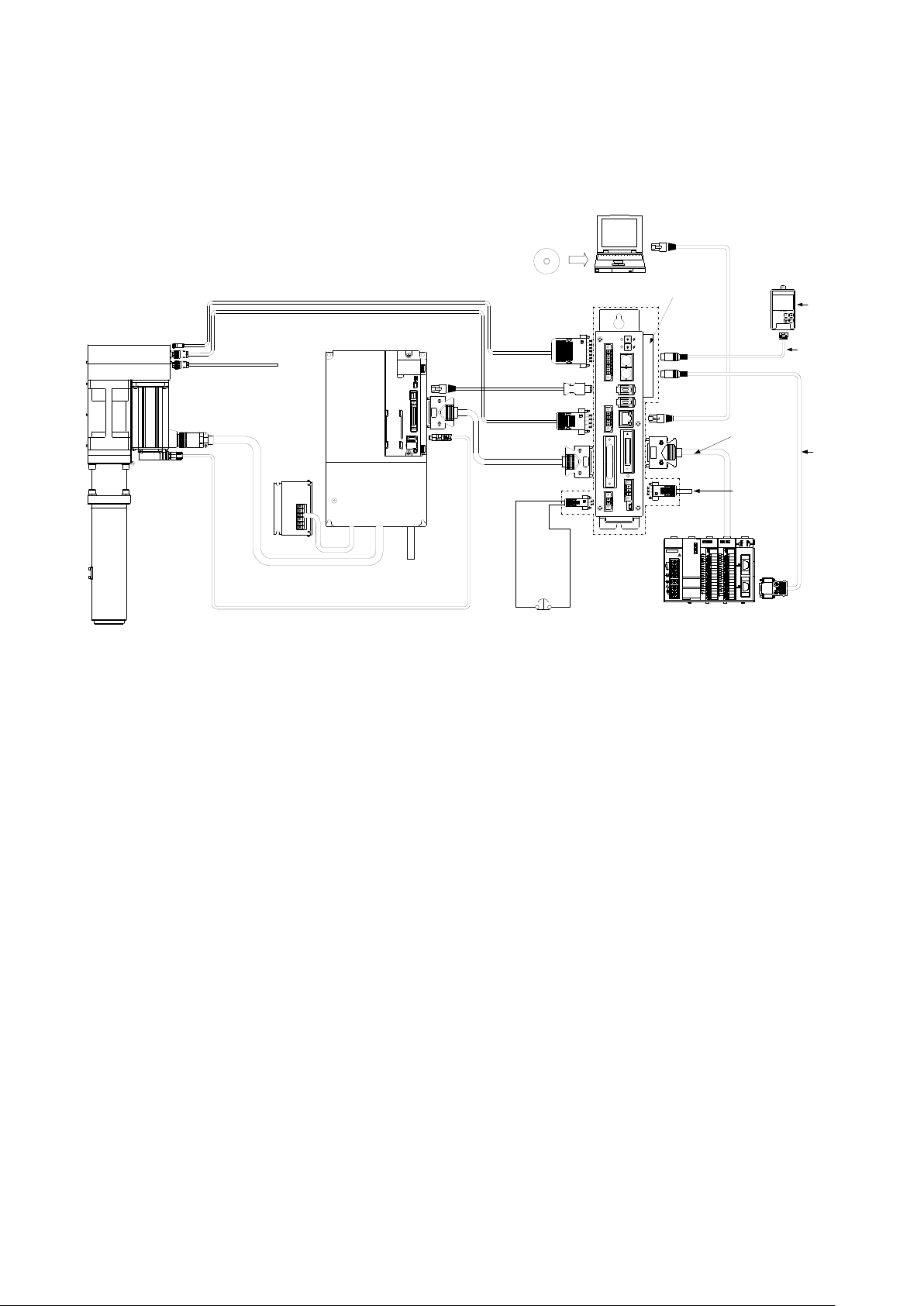
4.3. Connection figure (include options)
4.3.1. BS100
Instruction Manual Ver1 .08
BS-M3A-1B
Fig.4-3-1 BS100 Series
*1 The length of a cable is selectable from 5,10 and 20m. The junction cable is not
prepared.
*2 The length of a cable is selectable from 0.5 and 1m.
*3 The connectors in a dashed line are included to the controller set.
*4 This is unnecessary when using a FA Network Board.
*5 The type of LAN cable may not be crossing when using a HUB.
*6 The length of a LED Display cable is selectable from 5 and 10m.
*7 The model name of movable cable is CBSMT10R-**M.
*8 The model name of movable cable is MR-J3ENSCBL**M-H.
*9 Detail of the model name is different for each PLC type.
*10 A customer prepares cables.
*11 A customer controls this line.
*12 A external regeneration resister is an option.
- 18 -
Page 19
BS Controller for AC SERVO PRESS
AC Power *
11
AC200V
3φ
PLC
DC Power *11
DC24V
Emergency Stop *12
Servo Amp.
MR-J3-700A
BS Controller *3
BS
-
M3
A-
1
B
BS200 Tool
Sequence cable
CCKSQ-3M *4
Parallel I
/F cable
*
2
CBSPIF-
**M
Serial Com. cable *2
CBS422-**M
Origin Sensor cable *1
CBSGS-
**M
Load Cell cable *
1
*14
CBSLC-**M
Encoder cable *1 *8
MR
-J3
ENSCBL**M-L
Motor cable *1 *7
CBSMT
10-**
M
Brake cable
CBSBK
-
**M
*1
*
12
LAN cable(cross) *5
CCKLANC-5M
RS-
232
C cable
CCK232
-
3M
*10
FA Network
Board
Application
Software
Regen.Reg. *13
MR-RB31
MR-RB51
PC
LED Display
LDS-24
LED Display cable
CCKDSP-**M *6
Load Cell *9
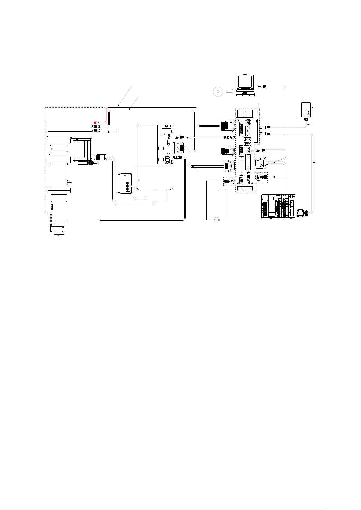
4.3.2. BS200
Instruction Manual Ver1 .08
BS-M3A-1B
Fig.4-3-2 BS200 Series
*1 The length of a cable is selectable from 5,10 and 20m. The junction cable is not
prepared.
*2 The length of a cable is selectable from 0.5 and 1m.
*3 The connectors in a dashed line are included to the controller set.
*4 This is unnecessary when using a FA Network Board.
*5 The type of LAN cable may not be crossing when using a HUB.
*6 The length of a LED Display cable is selectable from 5 and 10m.
*7 The model name of movable cable is CBSMT20R-**M.
*8 The model name of movable cable is MR-J3ENSCBL**M-H.
*9 The load cell is an option.
*10 Detail of the model name is different for each PLC type.
*11 A customer prepares cables.
*12 A customer controls this line.
*13 A external regeneration resister is an option.
*14 A model without a load cell needs a load cell cable to recognize a tool type.
- 19 -
Page 20

BS Controller for AC SERVO PRESS
5. Installation
5.1. Procedures for installing to control panel
5.1.1. Designing conditions for control box
5.1.2. Cautions when installing BS
5.1.3. The interval with MR-J3A
5.1.4. Noise Filter of MR-J3A
Instruction Manual Ver1 .08
BS-M3A-1B
Please be advised that the control box meets the general safety specifications.
Take the following into consideration.
1. The control box to house the BS should be a dustproof and drip-proof
structure.
2. Temperature in the control box should be from 0 to 50°C.
Heat generating amount of the BS depends on the operating status of
the Servo press. Install a fan, heat exchanger and heat radiation fin
according to the heat generating amount in the control panel.
3. Make sure to apply sealing to the cable outlet and window portion.
4. Consider mounting of the BS so that maintenance such as inspection and
removal is easily carried out.
When installing the main body of the BS, secure space of more than 25 mm (for
cooling) on both sides and more than 80 mm (for removal) above and under the
main body. Moreover, space 100mm or more is required for a front side because
of connectors.
Please make BS controller and MR-J3A adjoin. A connection cable should give
50cm or less as a standard.
Please be sure to insert a line noise filter in AC power supply of MR-J3A.
- 20 -
Page 21
BS Controller for AC SERVO PRESS
6. Installing lines
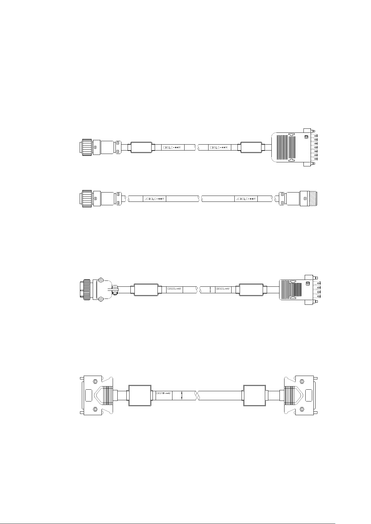
6.1. Load cell i/f(CN31)
6.2. Origin sensor i/f(CN32)
6.3. MR-J3A parallel i/f(CN33)
6.4. Emergency stop(CN34)
Instruction Manual Ver1 .08
BS-M3A-1B
It is used for the communication with strain gauge amplifier. The signal level
is an equivalent for RS-422. There is no necessity for connection in the system
without a load cell.
Cable type:CBSLC-**M(Basic Cable)
Cable type:JCBSLC-**M(Joint Cable)
An origin sensor is connected. Although, as for this system, absolute encoder
specification is also prepared, all tools are equipped with the origin sensor for
the initial position setup.
Cable type:CBSGS-**M
It connects with CN1 of MR-J3A. The position detection pulse of a motor and
the position instruction pulse to MR-J3A are contained. In order to avoid the
influence of a noise, short wiring is recommended as much as possible.
Cable type:CBSPIF-**M
An emergency stop SW is connected. The logic is normally closed. If it is made
opened, an emergency stop will be output to MR-J3A.
- 21 -
Page 22

BS Controller for AC SERVO PRESS
6.5. RS-232C(CN4)
Pin
number
Signal
name
Contents
1
Rxd
2
Txd
3
RTS
4
CTS
5
S-GND
Signal GND
6
7
P-
Power GND
8
24V
Power
6.6. RS-232C(CN5)
Pin
number
Signal
name
Contents
1
Rxd
2
Txd
3
4
5
S-GND
Signal GND
6
7
P-
Power GND
8
24V
Power
6.7. RS-485(CN6,7)
MI-232C**M
Instruction Manual Ver1 .08
BS-M3A-1B
It is a general-purpose serial communication port. Since DC24V power supply
is assigned, it is dangerous if it connects except an exclusive cable here. A
setup of a protocol and a baud rate is performed from CPS SP Configurator.
Controller side connector typr:HR12-10R-8SDL(HIROSE)
GND
Cable type:CCK232-**M(General)
:CCK232M-**M(Only for Mitsubishi Electric PLCs)
Usage:Connection with RS-232C unit of PLC etc.
It is a general-purpose serial communication port. Since DC24V power supply
is assigned, it is dangerous if it connects except an exclusive cable here. A
setup of a protocol and a baud rate is performed from CPS SP Configurator.
Controller side connector type:HR12-10R-8SDL(HIROSE)
GND
It connects with CN3 of MR-J3A. Although two connectors are prepared for
cascade connection, it cannot be used by 1:1. Please connect either of CNs 6
- 22 -
Page 23

BS Controller for AC SERVO PRESS
Pin
number
Signal
name
Contents
1
RD+
2 RD- 3
TD+ 4
TD- 5
S-GND
Signal GND
6
S-GND
Signal GND
6.8. Ethernet(CN8)
6.9. Parallel I/O (CN9)
CBS422-**M
CBS422-**M
Instruction Manual Ver1 .08
BS-M3A-1B
and 7.
The potential difference of GND for signals is permissible to 7V. When
communication is not stabilized, please turn on GND for signals of the pin
numbers 5 and 6 . If the metal cover of a right-hand side is removed toward BS
controller and 3 and 4 of the dip switch SW4 on the substrate are turned on
(above), GND for signals will become effective.
Cable type:
Controller side connector type:53462(Molex)
Cable type:CBS422-**M
It connects with a personal computer and exclusive application BS
Configurator performs a setup of BS controller etc. The protocol is UDP/IP.
They are 10 / 100M automatic change. It is necessary to make LAN setup of a
personal computer into a fixed IP address.
The example of a setting IP address 192:168:1:1
Subnet mask 255:255:0:0
Please use a cross cable, when you connect a personal computer and CPS
controller directly. Please use a straight cable, when you connect via a HUB.
It connects with a sequencer etc. and BS is controlled.
Cable type:CCKSQ-**M
(Refer to the wiring diagram for CPS<=>PLC connection.)
Connector:54306-3611(MOLEX)
- 23 -
One side is cut.
Page 24

BS Controller for AC SERVO PRESS
6.9.1. Bit assignment
Bit
number
Signal name
Contents
0
STOP
Program execution is interrupted, then a scram is carried
in a servo off state.
1
RESET
Alarm release and judgment output reset.
2
ORIGIN
Origin is started. Original position information
disappears by start of origin.
3
START
Program execution is started.
4
USER_SEL
User output selection.
5
JOG_SPD1/U_IN0
Bit 0 of JOG speed specification binaries/user input 0,
When JOG_ENA is ON, JOG speed is
JOG_ENA is off, it becomes the user input 0.
6
JOG_SPD2/U_IN1
Bit 1 of JOG speed specification binaries/user input 1,
are superposed.
7
JOG_ENA
JOG operation is permitted. Moreover, the output bit 3 is
changed to BAT.ALARM.
8
PNO1/JOG+
The bit 0 of the binary value which specifies an execution
JOG_ENA is ON, JOG operation is carried out in the
direction of +.
9
PNO2/JOG-
The bit 1 of the binary value which specifies an execution
. When
JOG_ENA is ON, JOG operation is carried out in the
direction of -.
10
PNO4
The bit 2 of the binary value which specifies an execution
program number.
11
PNO8
The bit 3 of the binary value which specifies an execution
program number.
12
PNO16
The bit 4 of the binary value which specifies an execution
program number.
13
SERVO_ON
Servo-on is directed to MR-J3A. In operation by PI/O,
at all.*1
14
U_IN2
User input 2.
15
U_IN3
User input 3.
Instruction Manual Ver1 .08
BS-M3A-1B
Input
out. After performing speed zero for 0.2 seconds, it will be
are superposed.
specified in four stages with the input bit 6. When
program number/+ Direction JOG are superposed. When
program number/- Direction JOG are superposed
unless it is in a servo-on state, a system does not operate
*1 On the tool operation screen and a program execution screen of BS Configurator,
SERVO_ON signal are ignored.
- 24 -
Page 25

BS Controller for AC SERVO PRESS
Bit
number
Signal name
Contents
0
ALARM(N.C)
Alarm. It is normaly closing. It turns off in the
state of alarm.
1
ALM_MR(N.C)
The alarm state of MR-J3A is shown. It is normal
closing.
2
READY
The completion of operation preparation.
3
IN_ORIGIN/BAT.ALARM
In origin mode/Battery alarm are superposed.
BAT.ALARM is chosen when JOG_ENA is ON.
4
RUN
It turns on during program execution.
5
OK
O.K. judging output. The output timing of
program.
6
NG
NG judging output.
7
IN_JOG/AREA1
Under JOG operation/Area signal1 are
ON.
8
P_ANS1/U_OUT0
The response of the bit 0 of binary value which
when USER_SEL is ON. It is the same to the bit
12.
9
P_ANS2/U_OUT1
The response of the bit 0 of binary value which
output 1 are superposed.
10
P_ANS4/U_OUT2
The response of the bit 1 of binary value which
output 2 are superposed.
11
P_ANS8/U_OUT3
The response of the bit 2 of binary value which
output 3 are superposed.
12
P_ANS16/U_OUT4
The response of the bit 3 of binary value which
output 4 are superposed.
13
U_OUT5
User output 5.
14
U_OUT6
User output 6.
15
USER_SEL_ANS
The response of USER_SEL.
16
BAT.ALARM
It is an output only for battery alarms. *1
17
ORIGIN_END
It turns on, when origin is completed. It turns off,
when origin is required. *1
18
PJ _WA IT
When using a post judgment, it turns on in the
state of waiting a judgement from a PC.
19
AREA2
Area signal 2.
20
AREA3
Area signal 3.
21
AREA4
Area signal 4.
22-31
RESERVED
Instruction Manual Ver1 .08
BS-M3A-1B
Output
y
O.K./NG is a time of executing jdg command in a
superposed. IN_JOG is chosen when JOG_ENA is
specifies an execution program number/User
output 0 are superposed. User outputs are chosen
specifies an execution program number/User
specifies an execution program number/User
specifies an execution program number/User
specifies an execution program number/User
* Above bit16 can be used only when Anybus option is chosen. It is that PI/O (CN9)
- 25 -
Page 26

BS Controller for AC SERVO PRESS
Instruction Manual Ver1 .08
BS-M3A-1B
suits from bit0 to bit15.
BS controller of version 1.02.23 or more is needed to use bit16 to bit18.
BS controller of version 1.02.31 or more is needed to use bit19 to bit21.
- 26 -
Page 27

BS Controller for AC SERVO PRESS
6.9.2. PIO connector pin assignment
PIN
No.
Bit
Color
Signal name
PIN
No.
Bit
Color
Signal name
1
I0
Gn
STOP
19
O0
LB/W
ALARM
2
I1
Br
RESET
20
O1
R/Bk
ALARM_MR
3
I2
Bl
ORIGIN
21
O2
Gn/Bk
READY
4
I3
Gy
START
22
O3
Br/Bk
IN_ORIGIN/BAT.ALA
RM
5
I4
Or
USER_SEL
23
O4
Bl/Bk
RUN
6
I5
Pr
JOG_SPD1/U_IN0
24
O5
Gy/Bk
OK 7 I6
Pn
JOG_SPD2/U_IN1
25
O6
Or/Bk
NG
8
I7
LB
JOG_ENA
26
O7
Pn/Bk
IN_JOG/AREA
9
I8 W PNO1/JOG+
27
O8
LB/Bk
P_ANS1/U_OUT0
10
I9
Gn/W
PNO2/JOG-
28
O9
W/Bk
P_ANS2/U_OUT1
11
I10
Bw/W
PNO4
29
O10
Gn/R
P_ANS4/U_OUT2
12
I11
Bl/W
PNO8
30
O11
Br/R
P_ANS8/U_OUT3
13
I12
Gy/W
PNO16/U_IN4
31
O12
Bl/R
P_ANS16/U_OUT4
14
I13
Or/W
SERVO_ON
32
O13
Gy/R
U_OUT5
15
I14
Pr/W
U_IN2
33
O14
Or/R
U_OUT6
16
I15
Pn/W
U_IN3
34
O15
Pn/R
USER_SEL_ANS
17 R
+24V
35 Bk
0V
18 R/W
+24V
36 Bk/W
0V
6.9.3. Wiring by the side of input
BS
17,18
DC24V
IN
IN
IN
Instruction Manual Ver1 .08
BS-M3A-1B
A pin number, the wiring color of PIO cable, and a signal name are shown.
The shield line of a cable is connected to the connector shell by the side of a
controller.
Connector(MOLEX:54306-3611)
Connector shell(MOLEX:54331-0361)
Cable(SUN LIGHTSX 0.2×18P)
- 27 -
Common voltage is DC24V and serves as a photo-coupler input.(Current is
about 5mA / 1 circuit.)
Page 28

BS Controller for AC SERVO PRESS
6.9.4. Wiring by the side of output
6.10. Control power supply (CN10)
6.11. Backup battery(CN11)
Please attach for a red lead to upside.
6.12. Anybus
BS
DC24V
L
L
L
OUT
OUT
OUT
17,18
35,36
Instruction Manual Ver1 .08
BS-M3A-1B
Open collector output (30mA / 1 circuit)
Control power supply 24V are connected.
The exclusive battery for SRAM backup is connected. Please connect a backup
battery in the state of control power supply ON. Although the life of a battery
is about five years, it changes a lot according to a use state and environment. If
battery voltage is less than 2.1V, BAT.ALARM (parallel output 3) turns on.
Even in such a case, inside information is held unless a control power supply is
turned off.
If the metal cover of the right side is removed toward CPS controller, the
- 28 -
Page 29

BS Controller for AC SERVO PRESS
6.13. Brake
RED(+24V)
WHITE(0V)
Instruction Manual Ver1 .08
BS-M3A-1B
connector for Anybus will appear. If it equips with Anybus card which HMS
offers, control equivalent to PI/O will be attained by networks, such as
CC-Link.
Although a tool with a brake can be chosen as an option, brake control is not
performed by BS controller. Please control a brake by the user system side. A
brake will be released if current is passed between a No. 1 pin and a No. 2 pin.
The brake is completely released in 0.2 seconds after turning on the current.
Please do not move the ram until the brake is released.
An option brake is an object for position maintenance to the last, and is not
applicable to dynamic braking.
If a jig weight added to the ram exceeds several percent of the tool maximum
thrust, the ram may fall naturally. In such a case, please use the brake for
position keeping.
MR-J3A builds in the dynamic brake. A sudden stop is possible if an emergency
stop (CN34) is opened.
Cable type:CBSBK-**M
- 29 -
Page 30

BS Controller for AC SERVO PRESS
6.14. Motor cable
6.15. Encoder Cable
Sield
Sield
Sield
Sield
Instruction Manual Ver1 .08
BS-M3A-1B
Please fully perform measure against a noise about the motor cable of MR-J3A.
Noise filters, such as a ferrite core, need to be attached.
The cables for BS100 series
Cable type:CBSMT10-**M
Cable type:CBSMT10R-**M (Cable for movable)
Cable type:CBSMT10L-**M
The cables for BS200 series
Cable type:CBSMT20-**M
Cable type:CBSMT20R-**M (Cable for movable)
Cable type:CBSMT20L-**M
Cable type:MR-J3ENSCBL**M-L
Cable type:MR-J3ENSCBL**M-H (Cable for movable)
- 30 -
Page 31

BS Controller for AC SERVO PRESS
Timing Chart
7.1. Power supply injection
7.2. Alarm reset
Alarm may not be canceled unless it outputs RESET twice.
7.3. Origin
O READY
O ALARM
I RESET
MR-J3A CTRL PW
0.5s
MR-J3A AC PW
BS CTRL PW 0.2s
O
READY
I
SERVO_ON
I ORIGIN
I STOP
I JOG_ENA
O IN_ORIGIN
/BAT.ALARM
O SERVO_ON
O ORIGIN_END
Origin is interrupted by STOP.
Orign normal end
Instruction Manual Ver1 .08
BS-M3A-1B
7.
The timing chart of fundamental operation is shown.
- 31 -
Page 32

BS Controller for AC SERVO PRESS
O READY_RUN
I START
I PRG.NO
O RUN
O ANS
O OK/NG
I RESET
7
7
55 4 4 8
8
7.4. JOG
7.5. Program execution
I SERVO_ON
I
JOG_ENA
I PNO1/JOG+
I PNO2/JOG-
I JOG_SPD1/U_IN0
I JOG_SPD2/U_IN1
O
IN_JOG/AREA
Instruction Manual Ver1 .08
BS-M3A-1B
When you turns on JOG_ENA, it is required for PNO1/JOG+, and PNO2/JOG-
to be in the state of off. It will become alarm if JOG_ENA is turned ON when
either of those signals is ON.
- 32 -
Page 33

BS Controller for AC SERVO PRESS
7.6.
Program execution using Post Judge
O READY_RUN
I START
Anybus
Setting Post Judge No.
I PRG.NO
O RUN
O PJ_WAIT
Collecting Waveform data
Judgement of PC
Ethernet
O ANS
O OK/NG
I RESET
5
4
5
4
Instruction Manual Ver1 .08
BS-M3A-1B
"Post Judge" is the function to take in waveform data to PC, to perform a
special analysis in PC, and to return judgment to BS controller. This function
can perform judgment processing which cannot be realized only by the
real-time operation within BS controller. Please refer to a BS_Configurator
handling description for details.
- 33 -
Page 34

BS Controller for AC SERVO PRESS
7.7.
Writing of a product name and a serial number
PLC
BS
PC
A product name, a serial
number, etc. are set to
each spindles via
AnyBus I/f.
Start each
spindles
The status sense to each
spindles.
A numerical and waveform
data are collected from the
ended spindles.
Data is saved.
Instruction Manual Ver1 .08
BS-M3A-1B
The flow chart in the case of recording a product name, a serial number, etc.
to numerical data using Anybus i/f is shown
- 34 -
Page 35

BS Controller for AC SERVO PRESS
7.8.
Post Judge
PLC
CPS
PC
PLC
BS
PC
A post judg
number is set up
vis AnyBus I/f.
Start each
spindles
The status sense to each
spindles.
A numerical and waveform
data are collected from the
ended spindles.
When using Post Judge,
waveform analysis is
performed according to the
specified judgment number.
A result is returned to BS.
O.K./NG is outputted
considering the
judgment from PC,
and an internal
judgment.
Instruction Manual Ver1 .08
BS-M3A-1B
"Post Judge" is the function to take in waveform data to PC, to perform special
analysis in PC, and to return a judgment to BS controller. This function can
perform judgment processing which cannot be realized only by the real-time
operation within BS controller. Please refer to a BS_Configurator handling
description for details.
- 35 -
Page 36

BS Controller for AC SERVO PRESS
8. Concept of stroke
8.1. Semi closed loop
8.2. Direction
8.3. System home position
8.4. User home position
8.5. System stroke limit
8.6. User stroke limit
Instruction Manual Ver1 .08
BS-M3A-1B
When using the Servo press, an incorrect setting of stroke will cause a
serious accident.Please be sure to understand concept of stroke well before
using the servo press. then design user programs, sequence, and system
after that.
The stroke value of a servo press is calculated from the encoder pulse of a
motor, and may not show the exact position of the ram always.
The right stroke value cannot be outputted before an origin return.
In proportion to load, a tool is distorted slightly. It is about 0.3mm at the
maximum load
When the mechanism of a timing belt or others breaks down, the actual
position and stroke value of the ram are-less correlating.
When the position of the ram has serious influence for operation of a system ,
we recommend you to form the sensor which detects the position of the ram
uniquely.
The direction where ram is extended is the direction of +.
It is used when adjusting offset of the whole system. It is set as a controller
using BS Configurator. When tools are exchanged, adjustment of an
attachment position can be easily performed by change of a system home
position.
It is the offset which can be arbitrarily set up in a user program. It specifies
using a home position table. It is set up on the basis of a system home position.
The stroke value of 32 pieces is prepared for the home position table. The
contents of a home position table can be changed by BS Configurator.
The stroke value treated in a user program starts from a user home position.
It is the maximum stroke value set to the tool table.*1 A setup can be
arbitrarily changed in the range exceeding it. The stroke value starts from an
origin sensor.
It is the stroke limit which can be described in a user program. The stroke
- 36 -
Page 37

BS Controller for AC SERVO PRESS
8.7. If the stroke limit is exceeded
8.8. A motion of the ram at the time of servo off
Instruction Manual Ver1 .08
BS-M3A-1B
value starts from a user home position.
If one of stroke limits is exceeded, a controller turns off READY and will be in
a servo off state. Please input RESET, in order to restore. If ON of READY is
checked, please move ram into a stroke limit by manual operation.
At the moment of servo-off, a ram may shift from various factors slightly. The
amount of shift is 1mm or less. In order to prevent the shift, please stop
servo-off or use the brake for position keeping.
*1 A tool table is the file various setting value about a tool is indicated to be. It
exists under the installation folder of BS Configurator. If a tool type is chosen
on a tool selection screen, the contents of a tool table will be displayed.
- 37 -
Page 38

BS Controller for AC SERVO PRESS
9. Connection with Personal Computer
9.1. Spindle number setup
The spindle number setting method
BS front
In the left figure, the spindle number
indle number in one
Please set up the number between
31.In the other setup, it becomes
an error.
9.2. IP address setup of BS controller
9.3. IP address setup of a personal computer
0
5
1
4
2
3
6
9
87
0
5
1
4
2 3
6
9
87
IDx10
IDx1
Instruction Manual Ver1 .08
BS-M3A-1B
In order to set up BS controller, exclusive application BS Configurator is
started, and it is necessary to connect with a personal computer. The procedure
is explained.
BS controller is connectable with the same communication system to 31 sets.
In this case, in order to discriminate each controller, it is necessary to set up a
spindle number.
is set as 5.
ID x 10 is 10 digits.
ID x 1 is 1 digit.
Please set up a sp
communication system not to overlap.
Duplication of a spindle number
causes a communication error.
01-
When a spindle number is changed, a spindle new number becomes effective
after a re-injection of a power supply.
The IP address of BS controller is set up like this 192:168: (master number
+14) : (spindle number).
A master number is set up by the SW1 bits 0-3 on CPU board. A master
number adds 1 to the binary value of 4 bits of SW1 low ranks. SW1 is visible if
the cover of an expansion bus is removed. A front panel side is a low rank bit.
The master number is set as 1 at the time of shipment. The controller of a
different master number is not connectable with one communication system.
The default gateway is 192.168.1.1.
In order to communicate with BS controller, it is necessary to set a fixed IP
- 38 -
address for a personal computer in the communication method of Ethernet.
Since the setting methods of a fixed IP address differ for every OS, refer to
Page 39

BS Controller for AC SERVO PRESS
9.4. LAN cable
9.5. Communicative check
9.5.1. Setup of operational authoority
Instruction Manual Ver1 .08
BS-M3A-1B
other data for them.
An example of a setting of an IP address
IP address 192.168.1.1(The default gateway of BS)
Subnet mask 255.255.0.0
Since it is not connectable with the Internet environment in almost all cases,
the personal computer set as the fixed IP address should be careful.
Please use a cross cable, when you link a BS controller and a personal
computer directly. Please use a straight cable, when you go via a hub.
If connection is completed, BS Configurator will be started and communication
will be checked. In the following explanation, the spindle number shall be set
as No. 1.
Operation authority can be set to BS Configurator. All operations are attained
by setting it as "All ". If setup-operation authority is chosen with a pull down
menu, an operation authority screen (Fig. 9-1) will be displayed. The radio
button of “All” is turned ON, a password is inputted, and O.K. button is clicked.
The initial value of a password is "2".
Fig.9-1 Operational authority screen
- 39 -
Page 40

BS Controller for AC SERVO PRESS
9.5.2. Setup of receive filter
9.5.3. Collection setup
9.5.4. Check of status
Instruction Manual Ver1 .08
BS-M3A-1B
If a setup-data collection-receiving filter is chosen with a pull down menu, a
receiving filter screen will be displayed. Please set up, as shown in Fig. 9-3.
Fig.9-3 Receive filter screen
At the pull down menu, check is put into setup-data collection-collection. (refer
to Fig. 9-4.)
Fig.9-4 Collection setup
If the status bar of the screen lower part is displayed as shown in Fig. 9-5,
communication is performed normally. Although various alarms are displayed
when no setup for BS controller is performed, there is no problem. As shown in
- 40 -
Page 41

BS Controller for AC SERVO PRESS
9.6.
Starting of two Configurators
Instruction Manual Ver1 .08
BS-M3A-1B
Fig. 9-6, when status is displayed, communication is not performed normally.
Please improve a setup from the beginning of Chapter 9.
Fig.9-5 Status bar Alarm state
Fig.9-6 Status bar Communication error state
It is also possible to install two BS Configurators in one PC, and to start
simultaneously. Starting of the 2nd Configurator displays the message "the
port cannot be used." It is because the 1st Configurator has already used the
port number 5008 (default value). Then, at the 2nd Configurator, it is set up so
that the port number except 5008 may be used. In the menu of the 2nd
Configurator,Setup-Data collection-Communication is chosen, and the
communication setting screen is opened.
Please choose 5009 at the list-box of All Port No. button, and click O.K. button.
Please re-start the 2nd Configurator. Two Configurators can be used if the
message about a port is not displayed. If two Configurators are used, data can
be displayed by the station.
Fig. 9-5 Communication Setup screen
- 41 -
Page 42

BS Controller for AC SERVO PRESS
9.7.
Use of two or more network interface cards
9.8.
Arbitrary IP address setup
9.8.1. Notes
Instruction Manual Ver1 .08
BS-M3A-1B
If LAN Interface Card Name in the Communication Setup screen of Fig. 9-5 is
used, the communication route between a PC and controllers can be specified.
Mixture of a network is avoidable if this function is used when using two or
more network interface cards. Moreover, if two Configurators are started and
data collection is performed by the separated network interface card, the time
of data collection can be shortened.
As shown in Fig. 9-5, the network interface card names are displayed in a
floating window by right click of the lower part of LAN Interface Card Name.
A setup will become effective, if LAN Interface Card Name of you wish is
chosen and O.K. button is clicked.
Arbitrary IP addresses can be set up now to the controller of a version 1.02.26
or later. On Fig. 9-5 Communication Setup screen if IP Address button is
clicked, Fig.9-6 IP Address Setup screen will open. The IP address of
Configurator and the IP address of a controller can be arbitrarily set up on this
screen. Address 4 is decided by the
spindle number. A spindle number
is set up with the rotary SWs of the
front upper part of a controller. The
setting range of a spindle number is
Fig.9-6 IP Address Setup screen
from 1 to 31.
Communication is impossible unless Configurator and a controller are the
same IP addresses. Moreover, it is necessary to also change the IP address of
the network interface card used with a personal computer. Please setup
addresses 1 and 2 with the same addresses of a controller.
A setup of a controller becomes effective after a re-injection of a power supply.
- 42 -
Page 43

BS Controller for AC SERVO PRESS
9.8.2. The communication method with an IP address unknown controller
Instruction Manual Ver1 .08
BS-M3A-1B
Please use a default fixed IP address to the controller with an unknown setup
of an IP address. When a spindle number is set as 71 to 99 with the rotary SW
of the upper part in front of a controller, the IP address of the controller is as
follows.
192.168.15.(spindle number - 70)
A new IP address becomes effective by re-injection of a power supply.
- 43 -
Page 44

BS Controller for AC SERVO PRESS
10. Starting
10.1. Starting procedure of BS controller
10.1.1. Attachment to equipment
10.1.2. Wiring
10.1.3. Control power supply injection
10.1.4. Attachment of a backup battery
10.1.5. Parameter setup of MR-J3A
10.1.6. Parameter setup of BS
10.1.7. Re-starting of a power supply
10.1.8. Check of a brake
10.1.9. Check of an emergency stop
10.1.10. Origin
10.1.11. Build a program.
Instruction Manual Ver1 .08
BS-M3A-1B
The outline procedure in the case of actually using BS controller is shown
below. The item which needs details is indicated after [2].
BS controller,MR-J3A and a tool are fixed to equipment.
Please wire with reference to a wiring diagram.
Only a control power supply is switched on. Please refer Section7 Timing Chart
7-1 Power supply injection.
The backup battery for holding the contents of a setting is attached.
The parameter of MR-J3A is set up. (It is required work only when MR-J3A is
purchased alone.)
Tool type selection, a setup of a stroke limit, etc. are performed from exclusive
PC application BS Configurator.
After a setup of a parameter, a power supply is turned off at once and only a
control power supply is switched on again. If alarm has not occurred, AC power
supply is also switched on. When alarm has occurred, please remove a cause
with reference to troubleshooting.
When a mechanical brake is chosen as an option, it checks that a brake is
taken off in the state of operation.
Please perform emergency stop operation and check that an emergency stop
operates.
Large restriction is applied to speed and output load when origin has not been
completed.
Build a program which suited the purpose using BS Configurator, and
transmit to BS controller.
- 44 -
Page 45

BS Controller for AC SERVO PRESS
10.1.12. Execution of a program
10.2. Parameter setup of MR-J3A
Caution 1
Caution 2
Caution 3
Parameter A
No.
Symbol
Name
Setting
Unit
Range
Change
required
PA01
*STY
Control mode
0000
0000-0235h
*
PA02
*REG
Regenerative option
0000
0000-000Ah
*
PA03
*ABS
Absolute position detection system
0000
0000-0004h
*
PA04
*AOP01
Function selection A-1
0000
0000-0011h
PA05
*FBP
Number of command input pulses
per revolution
16384
0/1000-50000
*
PA06
CMX
Electronic gear numerator
(Command pulse multiplying factor
numerator)
1
1-1048576
*
PA07
CDV
Electronic gear denominator
ommand pulse multiplying factor
denominator)
1
1-1048576
*
PA08
ATU
Auto tuning
0001
0000-0003h
PA09
RSP
Auto tuning response
12
1-32
PA10
INP
In-position range
100
pulse
0-10000
PA11
TLP
Forward torque limit
100.0
%
0.0-100.0
PA12
TLN
Reverse torque limit
100.0
%
0.0-100.0
PA13
*PLSS
Command pulse input from
0010
0000-0712h
PA14
*POL
Rotation direction selection
0
0-1 * PA15
*ENR
Encoder output pulses
16384
pulse/rev
1-100000
*
PA16
For manufacturer setting
0000
0000-FFFFh
PA17
*MSR
For manufacturer setting
0000
0000-FFFFh
PA18
*MTY
For manufacturer setting
0000
0000-FFFFh
PA19
*BLK
Parameter write inhibit
000C
0000-FFFFh
*
Instruction Manual Ver1 .08
BS-M3A-1B
If you run a program and there is an inconvenient portion, please add
correction and raise the completeness of a program.
When purchased in lump sum with a tool, the parameter of MR-J3A is already
set up.
About PA05 and PA15, those are setups for SP200 series. It is set
to 8192 in SP100 series. As for the parameter by which a setup is changed into
BS systems, * mark is attached to the Change required item.
About PA02, it is a setup of standard regeneration resistance.
When equipping with regeneration resistance of an option, a setup needs to be
changed.
About PA03, it is a setup of an incremental system. When you use
it by the absolute encoder system, please set it as 2.
- 45 -
(C
Page 46

BS Controller for AC SERVO PRESS
Parameter B
No.
Symbol
Name
Setting
Unit
Range
Change
required
PB01
FI LT
Adaptive tuning mode (Adaptive
filter )
0000
0000-0002h
PB02
VRFT
Vibration suppression control filter
(Advanced vibration suppression
control)
0000
0000-0002h
PB03
PST
Position command
(Position smoothing)
10
ms
0-20000
*
PB04
FFC
Feed forward gain
0 % 0-100
PB05
FFCF
For manufacturer setting
500
rad/s
10-4500
PB06
GD2
Ratio of load inertia moment to
servo motor inertia moment
0.8
times
0.0-300.0
PB07
PG1
Model loop gain
38
rad/s
1-2000
PB08
PG2
Position loop gain
58
rad/s
1-1000
PB09
VG2
Speed loop gain
327
rad/s
20-50000
PB10
VIC
Speed integral compensation
21.5
ms
0.1-1000.0
PB 11
VDC
Speed differential compensation
980
0-1000
PB12
OVA
For manufacturer setting
0 % 0-100
PB13
NH1
Machine resonance suppression
filter 1
4500
Hz
100-4500
PB14
NHQ1
Notch form selection 1
0000
0000-0330h
PB15
NH2
Machine resonance suppression
filter 2
4500
Hz
100-4500
PB16
NHQ2
Notch form selection 2
0000
000-0331h
PB17
NHF
Automatic setting parameter
000E
0000-031Fh
PB18
LPF
Low-pass filter
3141
rad/s
100-18000
PB19
VRF1
Vibration suppression control
vibration frequency setting
100.0
Hz
0.1-100.0
PB20
VRF2
Vibration suppression control
resonance frequency setting
100.0
Hz
0.1-100.0
PB21
VRF3
For manufacturer setting
0.00
0.00-1.00
PB22
VRF4
For manufacturer setting
0.00
0.00-1.00
PB23
VFBF
Low-pass filter selection
0000
0000-0011h
PB24
*MVS
Slight vibration suppression control
selection
0000
0000-0021h
PB25
*BOP1
Function selection B-1
0000
0000-1F12h
PB26
*CDP
Gain changing selection
0000
0000-0014h
PB27
CDL
Gain changing condition
10
0-9999
PB28
CDT
Gain changing time constant
1
ms
0-100
PB29
GD2B
Gain changing ratio of load inertia
moment
7.0
0.0-300.0
PB30
PG2B
Gain changing position loop gain
37
rad/s
1-2000
PB31
VG2B
Gain changing speed loop gain
823
rad/s
20-50000
PB32
VICB
Gain changing speed integral
compensation
33.7
ms
0.1-5000.0
Instruction Manual Ver1 .08
BS-M3A-1B
tuning mode
acceleration/deceleration time
constant
moment to servo motor inertia
倍
- 46 -
Page 47

BS Controller for AC SERVO PRESS
PB33
VRF1B
Gain changing vibration
setting
100.0
Hz
0.1-100.0
PB34
VRF2B
Gain changing vibration
setting
100.0
Hz
0.1-100.0
PB35
VRF3B
For manufacturer setting
0.00
0.00-1.00
PB36
VRF4B
For manufacturer setting
0.00
0.00-1.00
PB37
VP1
For manufacturer setting
100
pulse
0-32767
PB38
TGW1
For manufacturer setting
0.0
0.0-20.0
PB39
TGW2
For manufacturer setting
0.0
0.0-20.0
PB40
TGW3
For manufacturer setting
0.0
0.0-20.0
PB41
VRFF1
For manufacturer setting
112 5
Hz
1-1125
PB42
VRFF2
For manufacturer setting
112 5
Hz
1-1125
PB43
VRFQ
For manufacturer setting
0004
0000-0304h
PB44
For manufacturer setting
0000
0000-FFFFh
PB45
For manufacturer setting
0000
0000-FFFFh
Parameter C
No.
Symbol
Name
Setting
Unit
Range
Change
required
PC01
STA
Acceleration time constant
0
ms
0-50000
PC02
STB
Deceleration time constant
0
ms
0-50000
PC03
STC
S-pattern acceleration/deceleration
time constant
0
ms
0-1000
PC04
TQC
Torque command time constant
500
ms
0-20000
PC05
SC1
Internal speed command 1
100
r/min
0-50000
PC06
SC2
Internal speed command 2
500
r/min
0-50000
PC07
SC3
Internal speed command 3
1000
r/min
0-50000
PC08
SC4
Internal speed command 4
200
r/min
0-50000
PC09
SC5
Internal speed command 5
300
r/min
0-50000
PC10
SC6
Internal speed command 6
500
r/min
0-50000
PC 11
SC7
Internal speed command 7
800
r/min
0-50000
PC12
VCM
Analog speed command maximum
speed
0
r/min
0-50000
PC13
TLC
Analog torque command maximum
output
100.0
%
0.0-1000.0
PC14
MOD1
Analog monitor output 1
0000
0000-041Fh
PC15
MOD2
Analog monitor output 2
0001
0000-041Fh
PC16
MBR
Electromagnetic brake sequence
output
100
ms
0-1000
PC17
ZSP
Zero speed
50
r/min
0-10000
PC18
*BPS
Alarm history clear
0000
0000-0001h
PC19
*ENRS
Encoder output pulses selection
0000
0000-0021h
PC20
*SND
Station number setting
0
station
0-31
PC21
*SOP
Communication function selection
0040
0000-0150h
*
PC22
*COP1
Function selection C-1
0000
0000-1111h
PC23
*COP2
Function selection C-2
0000
0000-1511h
PC24
*COP3
Function selection C-3
0000
0000-0061h
Instruction Manual Ve r1 .08
BS-M3A-1B
suppression control vibration
frequency
suppression control resonance
frequency
- 47 -
Page 48

BS Controller for AC SERVO PRESS
PC25
*COP4
For manufacturer setting
0000
0000-0111h
PC26
*COP5
Function selection C-5
0000
0000-0111h
PC27
*COP6
For manufacturer setting
0000
0000-1111h
PC28
*COP7
For manufacturer setting
0000
0000-0000h
PC29
*COP8
For manufacturer setting
0000
0000-0001h
PC30
STA2
Acceleration time constant 2
0000
ms
0-50000
PC31
STB2
Deceleration time constant 2
0
ms
0-50000
PC32
CMX2
Command pulse multiplying factor
numerator 2
0
1-65535
PC33
CMX3
Command pulse multiplying factor
numerator 3
1
1-65535
PC34
CMX4
Command pulse multiplying factor
numerator 4
1
1-65535
PC35
TL2
Internal torque limit 2
1 % 0.0-100.0
PC36
*DMD
Status display selection
100.0
0000-011Fh
PC37
VCO
Analog speed command offset
0000
mV
-999-999
PC38
TPO
Analog torque command offset
1
mV
-999-999
PC39
MO1
Analog monitor 1 offset
0
mV
-999-999
PC40
MO2
Analog monitor 2 offset
0
mV
-999-999
PC41
MOSD1
For manufacturer setting
0
pulse
-1048576-1048
576
PC42
MOSD2
For manufacturer setting
0
pulse
-1048576-1048
576
PC43
For manufacturer setting
0000
0000-FFFFh
PC44
For manufacturer setting
0000
0000-FFFFh
PC45
For manufacturer setting
0000
0000-FFFFh
PC46
For manufacturer setting
0000
0000-FFFFh
PC47
For manufacturer setting
0000
0000-FFFFh
PC48
For manufacturer setting
0000
0000-FFFFh
PC49
For manufacturer setting
0000
0000-FFFFh
PC50
For manufacturer setting
0000
0000-FFFFh
Parameter D
No.
Symbol
Name
Setting
Unit
Range
Change
required
PD01
*DIA1
Input signal automatic ON selection
1
0C00
0000-0FFFh
*
PD02
*DIA2
For manufacturer setting
0000
0000-0000h
PD03
*DI1
Input signal device selection 1
(CN1-15)
00020202
00000000-003F
3F3Fh
PD04
*DI2
Input signal device selection 2
(CN1-16)
00212100
00000000-003F
3F3Fh
PD05
*DI3
Input signal device selection 3
(CN1-17)
00070704
00000000-003F
3F3Fh
PD06
*DI4
Input signal device selection 4
(CN1-18)
00080805
00000000-003F
3F3Fh
PD07
*DI5
Input signal device selection 5
(CN1-19)
00030303
00000000-003F
3F3Fh
PD08
*DI6
Input signal device selection 6
(CN1-41)
00202006
00000000-003F
3F3Fh
Instruction Manual Ve r1 .08
BS-M3A-1B
- 48 -
Page 49

BS Controller for AC SERVO PRESS
PD09
*DI7
For manufacturer setting
00000000
00000000-0000
0000h
PD10
*DI8
Input signal device selection 8
(CN1-43)
00000A0A
00000000-003F
3F3Fh
PD11
*DI9
Input signal device selection 9
(CN1-44)
00000B0B
00000000-003F
3F3Fh
PD12
*DI10
Input signal device selection 10
(CN1-45)
00232323
00000000-003F
3F3Fh
PD13
*DO1
Output signal device selection 1
(CN1-22)
0004
0000-3F3Fh
PD14
*DO2
Output signal device selection 2
(CN1-23)
000C
0000-3F3Fh
PD15
*DO3
Output signal device selection 3
(CN1-24)
0008
0000-3F3Fh
*
PD16
*DO4
Output signal device selection 4
(CN1-25)
0007
0000-3F3Fh
PD17
*DO5
For manufacturer setting
0003
0000-3F3Fh
PD18
*DO6
Output signal device selection 6
(CN1-49)
0002
0003-0003h
PD19
*DIF
Response level setting
0002
0000-3F3Fh
PD20
*DOP1
Function selection D-1
0000
0000-0011h
PD21
*DOP2
For manufacturer setting
0000
0000-0111h
PD22
*DOP3
Function selection D-3
0000
0000-0211h
PD23
*DOP4
For manufacturer setting
0000
0000-0111h
PD24
*DOP5
Function selection D-5
0000
0000-FFFFh
PD25
For manufacturer setting
0000
0000-FFFFh
PD26
For manufacturer setting
0000
0000-FFFFh
PD27
For manufacturer setting
0000
0000-FFFFh
PD28
For manufacturer setting
0000
0000-FFFFh
PD29
For manufacturer setting
0000
0000-FFFFh
PD30
For manufacturer setting
0000
0000-FFFFh
10.3. Parameter setup of BS controller
Instruction Manual Ve r1 .08
BS-M3A-1B
A parameter required in order to start a program is only tool type selection.
Please setup a stroke limit, acceleration time, and deceleration time if needed.
These can be set up from the tool selection screen of exclusive PC application
BS Configurator. The tool selection screen is shown in Fig. 10-3-1.
Fig. 10-3-1 Tool selection screen
- 49 -
Page 50

BS Controller for AC SERVO PRESS
10.4. Re-injection of a control power supply
10.5. Check of the brake
Instruction Manual Ve r1 .08
BS-M3A-1B
Tool type setting procedure is explained.
1) Choose a spindle number.
2) Choose a suitable tool name from the pull down list of tool types.
3) A click of the display area of the maximum stroke displays a numerical input
screen. The maximum stroke of a system is inputted. A positive numerical
value smaller than a default numerical value can be set up. If the Max. stroke
is set as longer 5-10mm than the actually used maximum stroke value, the
crash by incorrect operation etc. may be able to be prevented.
4) Set up deceleration time by the same method. Deceleration time is time
required for a tool to stop from top speed. Although a cycle time will be
shortened if deceleration time is shortened, the rate of regeneration load rises.
5) Set up acceleration time by the same method. Acceleration time is time until
a tool reaches top speed from a stop state. Although a cycle time will be
shortened if acceleration time is shortened, large current flows at the time of
acceleration. Since it leads to a rise of the rate of execution load, please be
careful.
6) A click of a send button displays a check screen. A click of O.K. sends the
contents of a display to BS controller.
7) After changing a tool type, a power supply needs to be re-supplied. Please
re-switch on a control power supply after equipping with a backup battery.
The control power supply of MR-J3A is switched on first. It is displayed on the
display area of MR-J3A as AL E6, and blinks. Since the power supply of BS
controller is not on, this shows that MR-J3A is in an emergency stop state. If
the power supply of BS controller is switched on, MR-J3A will be in a normal
state. Supposing MR-J3A is in an alarm state at this time, please specify a
cause from the contents of an alarm display, and remove the cause. In addition,
when alarm is generated, please remove a cause with reference to
troubleshooting.
When a mechanical brake is chosen as an option, please check that a brake is
taken off at the time of operation. Please control a brake by the sequencer
which controls a system. BS system is not equipped with the control and the
interlock function about a brake. Since there is a case where the system was
- 50 -
Page 51

BS Controller for AC SERVO PRESS
Cautions 1
Cautions 2
10.6. Check of emergency stop
Note
10.7. Origin
If origin is again started from the completion position of origin, ram will once
move in the minus direction. Please design a mechanism so that rum can
operate in the 10mm or more minus direction from the origin point.
10.8. Program creation
Instruction Manual Ve r1 .08
BS-M3A-1B
worked, having forgotten brake release as an example of a trouble, plentifully,
please be careful enough.
and closing. Since the noise control circuit is added to the brake control circuit
of CPS controller, it is not necessary to prepare a serge killer etc. by the user
side.
position maintenance. Please do not use it for braking.
Please check that the emergency stop input (CN33) of BS controller is released,
and MR-J3A will be in the emergency stop state. As for MR-J3A, a dynamic
brake operates in the state of an emergency stop.
In an incremental encoder system, whenever it switches on a control power supply, a
origin is needed. Moreover, also in an absolute encoder system, origin is surely required
at once. Execution of a program cannot be performed in the state of
un-completing an origin. Moreover, in the state of un-completing an origin ,
even in manual operation, the speed of a tool and an output are restricted
A serge noise generates a mechanical brake at the time of opening
The mechanical brake which is an option article is an object for
A dynamic brake is not applicable to position maintenance.
sharply. Speed is restricted to origin speed. An output is restricted to about
10% of the maximum output. Where the load exceeding it is applied, origin
cannot be performed.
There are the following as indispensable data at the time of creating a
program.
1. Contact position with a work
2. Permission Maximum Stroke
3. Permission Maximum Load
These parameters are greatly concerned with the safety of a system. Please
pay careful attention and define a numerical value.
Refer to the applicable item of the operation description of BS Configurator
for program language specification. We recommend you for the more
unfamiliar one to use the program automatic generation function of BS
- 51 -
Page 52

BS Controller for AC SERVO PRESS
10.9. Execution of a program
Instruction Manual Ve r1 .08
BS-M3A-1B
Configurator. If the numerical value is set up according to the guide screen, a
program will be generated automatically.
Please send the created program to a BS controller.
Although execution of a program is usually performed by PI / O operation, it is
possible even if it uses the program execution function of BS Configurator.
When wiring of PI/O and a control system are incomplete, it is effective as a
check means of operation.
We recommend use of the numerical monitor of BS Configurator, or a
waveform monitor function to debugging of a program. Please refer to the
applicable item of a BS Configurator operation description about those details.
- 52 -
Page 53

BS Controller for AC SERVO PRESS
11. Troubleshooting
11.1. The state display by LED
LED3
LED4
The state of a
Note
STATUS
CODE
Color
State
Color
State
off off
Power supply
off
It may be, when CPU is not
operating normally.
off
Green
Blink
Servo off
It is in the state of servo off.
Green
on off
READY
It is in the state in which program
execution is possible.
Orange
on off
Under program
execution
Blink
-
Battery alarm
Blink of STATUS is not based on a
color but means battery alarm.
Even when LED3 is off, it is
compulsorily green and blinks.
Red
on
Green
on
Slight alarm
It is the alarm resulting from I/O
operation and timing.
Red
on
Orange
on
Middle alarm
It is alarm to be set up according to
CPS SP Configurator.
Red
on
Red
on
Serious alarm
It is the alarm resulting from the
environment of a controller, and
hardware.
Instruction Manual Ve r1 .08
BS-M3A-1B
Alarm is generated in many cases in multiplex, and the contents of a display
machine etc. are overwritten by the newest alarm. In order to know the details of
alarm, we recommend you to use the alarm history function of BS Configurator. In
an alarm history function, a monitor is possible for the alarm history of BS
controller and MR-J3A.
There are four LEDs in the front panel upper part of BS controller. Among
those, two pieces are assigned to STATUS and CODE and display the internal
state of CPS controller in the state of these lightings.
controller
-
-
- 53 -
Page 54

BS Controller for AC SERVO PRESS
11.2. Alarm code table
Alarm
code
Name
Meaning/correspondence
001
The abnormalities
Abnormalities were discovered by the data of the backup
The domain containing abnormalities
Consumption of a
he omission of the connector of a
. When a backup file
backup)
002
The abnormalities
The output is over tolerance level at the time of the
calibration of a load cell. Please check calibration value
Configurator handling
has been
, calibration value may be out of order. In this
case, repair is required.
003
The abnormalities
The no-load output value of a load cell is over tolerance
y the monitor
output value may be out of order. In this case, repair is
required. Moreover, it may become abnormalities in
the cause of load.
006
Program
The specified user program does not exist in a controller.
Please check that an appointed program number is in a
controller.
007
Tool
A tool type has not been registered. Please set a suitable
tool type as a controller. Consumption of a backup battery
he omission of the connector of a backup battery is
Configurator need to be set up. When a backup file exists,
backup)
008
Origin error
Abnormalities occurred during origin and origin was not
ings can be considered as a
STOP signal is inputted,
Excessive load exists. Please remove these causes and
perform origin operation again.
009
The abnormalities
in SG amplifier
The communication with a tool is unusual. Please check
the connection of an encoder cable(CN31).
010
The abnormalities
The types of the tool connected with the tool type set as
Instruction Manual Ve r1 .08
BS-M3A-1B
An alarm code cannot be known only with a controller. Please use BS
Configurator or the below-mentioned option article.
Basic alarm code
in RAM backup
in CAL
in ZERO
domain of SRAM.
is shown by the detailed alarm code.
backup battery or t
backup battery is suspected(CN11)
exists, restoration can restore easily.
(Refer BS_Configurator handling description 7-6-2
by manual operation. (Refer BS
description 4-3 proofreading) When a tool
crashed
level. Please check a load cell output b
function. (Refer BS Configurator handling description 4-3
proofreading) When a tool has been crashed, no-load
ZERO if a program is started when load is applied to a
tool. In this case, please start a program after removing
un-registering.
un-registering.
or t
suspected(CN11). All itmes of thr setup menu in BS
restoration can restore easily.
(Refer BS Configurator handling description 7-6-2
completed. The following th
factor which bars origin,
- 54 -
Page 55

BS Controller for AC SERVO PRESS
in a tool type
the controller differ. Please set the right tool type to the
controller.
011
The abnormalities
Abnormalities were discovered at the contents of
Configurator. Please consult with a operating window,
when there is an unusual numerical value.
013
Basic parameter
The parameter which accompanies a tool has not been
Configurator need to be set up. When a backup file exists,
backup)
014
The abnormalities
in the contents of
The parameter exceeding rating is contained in the
program under execution. Please check the contents of a
user program. When each table is being referred to with
speed, the position, and the load parameter, please check
the contents of each table.
016
The abnormalities
in a driver
It is the alarm about a motor driver. Please refer to a
detailed alarm code.
017
AC power supply
is OFF state.
AC power supply is in off state. Please check the state of
power supply.
018
The abnormalities
in origin
A program was started in the state of un-completing an
origin.
019
The abnormalities
in a data
Access for data collection was not made from PC during
user program execution. The abnormalities of data
collection PC and Ethernet cable are suspected. When
please set this
function off.
020
Emergency stop
STOP signal of a general-purpose input operated. Please
turn off STOP signal and perform reset operation.
021
Tool type
error
The tool type of the performed program differs from the
022
Power supply
demand
Since the backup file was restored, a power supply needs
023
Backup area
partial error
The checksum error occurred in a part of backup domain.
024
The abnormalities
in JOG operation
signal
When JOG_ENA is turned on, JOG+ or JOG- has already
025
It was started in
AC power supply
OF F.
It was going to work the controller in spite of OFF state
026
Since it is
, it
cannot start.
It was going to start the program in spite of the state of
027
Under operation
of JOG or origin
It was going to start the program during JOG operation
or origin.
029
Anybus
It failed in initialization of the card which was equipped
Instruction Manual Ve r1 .08
BS-M3A-1B
in EEPROM
or gain parameter
un-registering.
Program
EEPROM. Please check the numerical value of each item
on the maintenance information screen of BS
registered. All itmes of thr setup menu in BS
restoration can restore easily.
(Refer BS Configurator handling description 7-6-2
collection failure
mismatching
re-injection
JOG_ENA ON
you do not perform data collection,
tool type set to the controller.
to be re-supplied.
turned on.
of AC power supply.
ON of JOG_ENA.
- 55 -
Page 56

BS Controller for AC SERVO PRESS
initialization
error
to Anybus. Please check the Anybus card.
030
Tool change error
The power supply is not re-switched on after change of a
tool type. A power supply is re-switched on.
031
Anybus error
Abnormalities have occurred in Anybus.
032
A collision of PC
While opening the tool proofreading screen or the tool
operation screen of BS Configurator,, program start
operation was made via I/O. Please close the tool
a tool operation screen of BS
Configurator at the time of program execution.
033
The error of
kind
The kind of board equipped to Anybus is wrong. Please
set to the controller, and the
kind of actual board.
034
Absolute position
The encoder information of MR-J3A was lost. The
onsumption of the
isconnection of an encoder
This alarm is not resettable unless the power
of a power supp l y, it needs origin operation.
035
The abnormalities
initialization
It failed in communication initialization with MR-J3A.
J3A is on.
check a power supply injection sequence.
036
The abnormalities
The communication with MR-J3A is impossible. Please
J3A is on.
Moreover, please check a communication cable. Please
check a power supply injection sequence.
037
Torque restriction
value is
inaccurate.
The setting value of DAC for a torque restriction voltage
038
Alarm
in
Alarm is generated in MR-J3A. The contents of alarm of
J3A can be checked by the alarm history function of
BS Configurator, or the MR-J3A alarm history function.
040
Servo-off starting
error
Origin, JOG, or the program was started in the state of
Servo-off. Please start after turning on SERVO_ON.
041
MR-J3 ABS setup
Some error is in a parameter setup of MR-J3A. Encoder
correctly.
042
MR-J3 ABS type
It failed in reading of encoder specification at
initialization after a power supply injection of a
Please check the communication cable which
J3A with CN6 or CN7 of
BS-M3A-1B.
051
Post judgment
Although the post judgment was used, PC did not answer
within regulation time. Please check that PC is in a data
collection state. Moreover, about a setup of the response
Configurator handling
description 7-7-7 others.
053
Anybus
The communication with the master of a network
Instruction Manual Ve r1 .08
BS-M3A-1B
and PLC
proofreading screen or
Anybus board
is lost
in MR-J3A
communication
in MR-J3A
communication
proofreading
MR-J3A.
check the kind of Anybus
following causes can be considered-c
backup battery of MR-J3A,d
cable.
supply of BS system is re-switched on. After a re-injection
Please check whether the power supply of MRMoreover, please check a communication cable. Please
check whether the power supply of MR-
output is over the range.
MR-
error
specification is not set as the absolute type via serial
communication. Please set up the parameter of MR-J3A
read error
controller.
connects CN3 of MR-
response error
time from PC, please refer BS
- 56 -
Page 57

BS Controller for AC SERVO PRESS
communication
error
stopped. The omission of the communication cable or the
abnormalities of the master are suspected.
098
The abnormalities
in a battery
Backup battery voltage fell. A battery needs to be
exchanged.
Alarm
code
Name
Meaning/correspondence
102
FPGA error.
They are the abnormalities of a logic IC. Repair is
required.
103
Updating timing
violation of a basic
parameter.
A tool type setup was performed during servo-on.
Please do not perform a tool type setup during
program execution.
104
Origin isn’t
finished.
Positioning operation was performed for orogin not to
be performed. Please perform origin.
200
The abnormalities
Abnormalities were discovered by the contents of a
motor table. Please refer to the details of a motor
table.
202
Outside of the
current.
Abnormalities were discovered by the contents of a
motor table. Please refer to the details of a motor
table.
203
Rated current is
outside of the
range.
Abnormalities were discovered by the contents of a
motor table. Please refer to the details of a motor
table.
204
Outside of the
Abnormalities were discovered by the contents of a
motor table. Please refer to the details of a motor
table.
207
Outside of the
max rated
current.
Abnormalities were discovered by the contents of a
a motor
table.
211
Outside of the
direction.
Abnormalities were discovered by the contents of a
212
Outside of the
direction.
Abnormalities were discovered by the contents of a
213
Outside of the
resolution.
Abnormalities were discovered by the contents of a
214
Outside of the
range-origin speed.
Abnormalities were discovered by the contents of a
tool table. Please refer to the details of a tool table.
215
Outside of the
range-creep speed.
Abnormalities were discovered by the contents of a
tool table. Please refer to the details of a tool table.
216
Outside of the
sensor logic.
Abnormalities were discovered by the contents of a
217
Outside of the
Abnormalities were discovered by the contents of a
Instruction Manual Ve r1 .08
BS-M3A-1B
Detailed alarm code
It is a detailed alarm code in the case of the abnormalities in a driver
in a motor type
range-rated
range-max speed.
range-
range-encorder
range-origin
range-encorder
motor table. Please refer to the details of
tool table. Please refer to the details of a tool table.
tool table. Please refer to the details of a tool table.
tool table. Please refer to the details of a tool table.
range-origin
tool table. Please refer to the details of a tool table.
- 57 -
Page 58

BS Controller for AC SERVO PRESS
range-load cell
type.
tool table. Please refer to the details of a tool table.
218
Outside of the
limit.
Abnormalities were discovered by the contents of a
308
Outside of the
stop speed
ratio.
Abnormalities were discovered by the contents of a
309
Outside of the
range-deceleration.
Abnormalities were discovered by the contents of a
tool table. Please refer to the details of a tool table.
310
Outside of the
ratio.
Abnormalities were discovered by the contents of a
400
Outside of the
They are the abnormalities of a control mode
on of a microcomputer is
suspected. Repair is required, if, so that it may occur
frequently.
401
Over limit-target
Since there was a possibility of the stroke limit having
been exceeded or exceeding, it went into the stop
mode.
402
Over limit-target
speed.
The speed target value exceeding the limit was set up.
404
Inconsistency of
pulus limits.
- side of stroke restriction value was set up more
greatly than + side.
410
Outside of the
The parameter in the positioning mode is unusual.
Incorrect operation of a microcomputer is suspected.
Repair is required, if, so that it may occur frequently.
411
Outside of the
time.
The setting value of acceleration time is over the
le or check
a tool setup.
530
Z phase ditected
The encoder incorrect-counted. Incorrect operation by
the abnormalities in an encoder cable and the noise
can be considered. Please add filters, such as a ferrite
core, to a noise generation source.
532
ABZ of encoder
alarm.
Disconnection detection of an encoder cable operated.
Please check the plug of a connector.
536
Z-phase lost
Z phase of the encoder was not detected more than a
The failure relevant to an encoder cable or
an encoder is suspected.
540
Limit over-stroke.
The stroke limit was exceeded. Please move by
manual operation after reset at within the limits.
550
Limit over-current
Current restriction value was exceeded at the time of
, the big load at the time of
should set the concerned part of a tool table as
proper value.
551
Limit over-stroke
The stroke range currently assumed by origin
originsensor is suspected.
load in
Please check
Load cell recieve
The communication state with load cell amplifier is not good.
Instruction Manual Ve r1 .08
BS-M3A-1B
range-current
range-
range-deceleration
range-control
mode.
stroke.
range-stroke mode.
tool table. Please refer to the details of a tool table.
tool table. Please refer to the details of a tool table.
tool table. Please refer to the details of a tool table.
parameter. Incorrect operati
range-acceleration
wrong timing.
in origin mode.
in origin mode.
552 Limit over-
origin mode
553
range. Please improve a setup of a tool tab
fixed term.
origin. In such a case
origin
sequence was exceeded. The abnormalities of an
Load restrictions worked before origin finished.
whether there is any nothing that bars a motion of ram.
- 58 -
Page 59

BS Controller for AC SERVO PRESS
re against a noise is required. It is, when the load
1001-1031
The abnormalities
in a program
Abnormalities were detected in the program number
(detailed alarm code -1000).
1101-1131
The abnormalities
in Judge Table
Abnormalities were detected in Judge Table number
(detailed alarm code -1100).
1201-1231
The abnormalities
in Zone Table
Abnormalities were detected in Zone Table number
(detailed alarm code -1200).
1301
The abnormalities
in Position Table
Abnormalities were detected in Position Table.
1302
The abnormalities
in Load Table
Abnormalities were detected in Load Table.
1303
The abnormalities
in Speed Table
Abnormalities were detected in Speed Table.
1304
The abnormalities
Table
Abnormalities were detected in Home Position Table.
1400
The abnormalities
in Tool Table
Abnormalities were detected in Home Tool Table.
1601
The abnormalities
in Numerical data
Abnormalities were detected in the pointer of
Numerical data.
1602
The abnormalities
in Numerical data
Abnormalities were detected in Numerical data.
1603
The abnormalities
in Waveform data
Abnormalities were detected in the pointer of Normal
Waveform data.
1604
The abnormalities
in Waveform data
Abnormalities were detected in Normal Waveform
data.
1605
The abnormalities
in Waveform data
Abnormalities were detected in the pointer of NG
Waveform data.
1606
The abnormalities
in Waveform data
Abnormalities were detected in NG Waveform data.
1701
The abnormalities
in Alarm history
Abnormalities were detected in the pointer of Alarm
history.
1702
The abnormalities
in Alarm history
Abnormalities were detected in Alarm history.
1801
The abnormalities
in Backup time
Abnormalities were detected in Backup time.
1802
The abnormalities
times
Abnormalities were detected in Total running times.
1803
The abnormalities
Total running
distance
Abnormalities were detected in Total running
1901-1904
The abnormalities
in Others
Abnormalities were detected in Others.
1905
The abnormalities
in JOG speed
Abnormalities were detected in JOG speed
1906
The abnormalities
in Load/Stroke
output interval
Abnormalities were detected in Load/Stroke output
Instruction Manual Ve r1 .08
BS-M3A-1B
error The measu
sensor connector has fallen out.
in Home Position
in Total running
in
distance.
interval.
- 59 -
Page 60

BS Controller for AC SERVO PRESS
1907
The abnormalities
in Others
Abnormalities were detected in Others.
1908
The abnormalities
in Load Rate
Parameters
Abnormalities were detected in Load Rate
2001-2010
The abnormalities
in Unused area
Abnormalities were detected in Unused area.
Instruction Manual Ve r1 .08
BS-M3A-1B
Parameters.
- 60 -
Page 61

BS Controller for AC SERVO PRESS
12. Regeneration
Caution
12.1. Lowering regeneration frequency
12.2. Regeneration option
Instruction Manual Ve r1 .08
BS-M3A-1B
The regeneration electric power which occurs by rapid slowdown is changed
into heat by regeneration resistance. In BS Configurator, a monitor is possible
for the rate of regeneration load. If the rate of regeneration load exceeds 85%,
it will become the alarm of the abnormalities in regeneration (caution). There
are two methods in avoiding the abnormalities in regeneration. The first is the
method of lowering regeneration frequency.、The second is the method of using
more nearly mass regeneration resistance.
rate of regeneration load exceeds 85%, by BS controller, warning is also treated
as alarm.
Although there are a method of lengthening slowdown time, and a method of
taking long operation pause time in order to lower regeneration frequency ,in
all a cycle time becomes long.
The larger regeneration option is prepared by Mitsubishi Electric than the
regeneration resistance built-in MR-J3A. Refer to the technical data of MR-J3A
for the details of a regeneration option.
When it corresponds to the regeneration of high frequency by the
regeneration option, it is necessary to consider the temperature rise in a
control board. I ask measure, such as attaching a cooling device so that the
temperature in a control box may not exceed 50 degrees C, of you.
Although it is the warning of fault regeneration as MR-J3A when the
- 61 -
Page 62

BS Controller for AC SERVO PRESS
13. Absolute encoder system
13.1. Setup
13.1.1. Setup to BS controller
13.1.2. Setup to MR-J3A
13.1.3. Wearing of a backup battery
13.2. The alarm release method
Important
Instruction Manual Ve r1 .08
BS-M3A-1B
MR-J3A corresponds to the absolute encoder system. Therefore, BS system can also
be equivalent to the absolute encoder system.
In the tool type of absolute encoder system, "A" is attached to the end of tool
type form.
PA03 is set as 0002 by parameter setup. In the 1st power supply injection after
performing this setup, the alarm of AL.25-" absolute position disappearance"
will be generated at MR-J3A. The release method of the alarm is mentioned
later.
Please equip CN4 of MR-J3A with the backup battery of exclusive use.
The alarm of AL.25 "absolute position disappearance" will occur in MR-J3A by
a power supply injection of the first time after absolute encoder system setup,
consumption of a backup battery and disconnection of an encoder cable. AL.25
will be canceled if the power supply of MR-J3A is re-switched on after
removing some causes of alarm.
power supply of BS controller is switched on when AL.25 occur, BS controller
will be in the state where origin is not completed. In this case, execution of a
program etc. cannot be performed unless origin operation is completed. When
AL.25 occurs, please perform origin operation after re-switching on a power
supply.
If wiring connection of the BS system is made normally and the
- 62 -
Page 63

BS Controller for AC SERVO PRESS
14. Load-Sensor-less System
Item
load-sensor-less
with load sensor
Load value
It computes from motor
current.
Load cell value
Accuracy
15%@Tool rating
2%@Tool rating
Renewal cycle of
load value
1ms
1ms
At the time of
It has no problem to the
system.
A load cell carries out plastic
modification in about 150% of
its rating.
Disconnection
No
It is detected by ZERO and
CAL alarm.
Price
Only the part without a load
cell is cheaper.
Only the part of a load cell is
more expensive.
Instruction Manual Ve r1 .08
BS-M3A-1B
The load-sensor-less tool is also prepared in this system. The special feature is
shown in a comparison table.
±
crash
Since there are the above special features, please choose the system according to
the use.
amount of -proof of a tool and a
±
- 63 -
Page 64

BS Controller for AC SERVO PRESS
15. Tool Type Discernment
Instruction Manual Ve r1 .08
BS-M3A-1B
Information, such as a tool type name and load cell proofreading value, is written in
BS tool. It will become alarm if the tool name different from the tool linked to BS
controller is set up.
About connection of BS controller and MR-J3A, there is no function to recognize the
capacity of MR-J3A in BS controller. Therefore, incorrect connection is not detected.
In multi-spindles composition, I ask sufficient consideration for connection of BS
controller, MR-J3A, and a motor of you.
- 64 -
Page 65

BS Controller for AC SERVO PRESS
16. Stole
Instruction Manual Ve r1 .08
BS-M3A-1B
A stole can be carried out with arbitrary load value by executing a load restriction
command on a program. Load accuracy is a 15%@FS grade. In the case of a stole,
droop pulses occurs at a maximum of 2 rotations on a motor. If the procedure of
canceling load restrictions is mistaken, ram will operate abruptly, and there is a
risk of causing breakage of a work and a system. Please cancel load restrictions
after solving droop pulses.
- 65 -
Page 66

BS Controller for AC SERVO PRESS
17. Others
17.1. The options of the servo press
BS Configurator
It is exclusive application software
which operates on Windows of IBM
etup of a
user program, data collection, etc. can
LED DISPLAY
This is two steps of 6 figure display
232C port of a
controller. Monitors, such as a
Electromagnetic brake
It is effective when preventing the slide
off. A
BS Configurator
Instruction Manual Ve r1 .08
BS-M3A-1B
The options of the servo press are shown below.
compatible machine. S
controller, a maintenance, and editing a
be performed.
machines by 7 segment LED. It
connects with RS-
numerical result, can be done.
of the ram at the time of servo
brake is not controlled by BS controller.
- 66 -
Page 67

BS Controller for AC SERVO PRESS
18. Article of Consumption
18.1. Battery
18.1.1. The detection method
18.1.2. The exchange method
18.1.3. Management
18.1.4. Clock setup
18.2. Parts having service lives of MR-J3A
Part name
Life guideline
Smoothing capacitor
10 years
Relay
Number of power-on and number of
stop times : 100,000 times
Cooling fan
10,000 to 30,000hours (2 to 3 years)
Absolute position battery
Approx. 10,000 hours (battery life with
power off)
Instruction Manual Ve r1 .08
BS-M3A-1B
The visual check of the abnormalities in a battery can be carried out by blink of
LED3 STATUS in the front panel upper part of a controller.
Moreover, since a battery unusual signal is outputted also from a
general-purpose output, it is detectable also by PLC.
Although the life of a backup battery is about five years, it varies greatly
according to a state of operation and environment of operation. If the
abnormalities in a battery occur, please exchange a backup battery quickly.
Battery exchange is carried out in the state of power supply ON. If batteries
are exchanged in the state of power supply off, a backup circuit will not operate
normally but consumption of a battery will progress remarkably.
Exchange date of a backup battery is memorized in a controller by BS
Configurator, and a monitor of it is possible. Moreover, calculation of the net
backup time is count. Please use it for management of a backup battery.
This controller is equipped with the clock function. In the case of battery
exchange, we recommend you to setup of a date and time.
Please refer to the collection of servo amplifier technical data of MR-J3A for
details.
emergency
- 67 -
Page 68

BS Controller for AC SERVO PRESS
19. Maintenance of Tool
20. Cautions on abandonment
Revision history
CORETEC Fastening Innovators
500 Akahama,Soja City,
Okayama Pre 719
Sales Dept. TEL 0866
Instruction Manual Ve r1 .08
BS-M3A-1B
About a tool, we recommend you implementation of a periodical maintenance.
By BS controller, the number of times of operation and the total information on
the mileage of a ball screw are managed. A monitor is possible for these
information by the maintenance information function of BS Configurator. A
near maintenance cycle can be obtained from these information and the load
situation of a program. Please ask for details the window in your duty.
An overhaul must be carried out at our company and any overhaul carried
out by another company falls outside our guaranteed coverage.
If you have any questions on the Servo press, please contact us.
Devices into which electronic equipment is mounted must not be discarded as
domestic waste. Please obey the local laws or regulations effective at present
for electrical and electronic equipment waste.
-1121
-94-9016
- 68 -
 Loading...