

NeMo CMTS
User’s Guide

010804

NeMo CMTS User’s Guide
- i -
Important Notice
This guide is delivered subject to the following conditions and restrictions:
§ This guide contains proprietary information belonging to Coresma, Ltd. Such
information is supplied solely for the purpose of explicitly assisting properly
authorized users of NeMo CMTS System™.
§ No part of the contents may be used for any other purpose, disclosed to any
person or firm or reproduced by any means, electronic and mechanical, without
the express prior written permission of Coresma, Ltd.
§ The text and graphics are for the purpose of illustration and reference only. The
specifications on which they are based are subject to change without notice.
§ The software described in this document is furnished under a license. The
software may be used or copied only in accordance with the terms of that
agreement.
§ Information in this document is subject to change without notice. Corporate and
individual names and data used in examples herein are fictitious unless
otherwise noted.
Copyright 2001 Coresma, Ltd.
NeMo CMTS, NeMo Modem are trademarks of Coresma Ltd. All other product names
are trademarks or registered trademarks of their respective owners, and are hereby
acknowledged.
- ii -
Safety Instructions
Caution! Risk of Electric Shock!
Do not open the cover under any circumstances.
§ Dangerous voltages inside.
§ No user serviceable parts inside.
§ Refer to qualified service personnel.
Explanation of Graphical Symbols:
This symbol is intended to alert the user to the presence of non-insulated
"dangerous voltage" within the product's enclosure that may be of sufficient magnitude
to constitute a risk of lethal electric shock to persons.
This symbol is intended to alert the user to the presence of important operating,
maintaining and servicing instructions in the literature accompanying the appliance.
Failing to comply with this instruction may result in a hazard.

NeMo CMTS User’s Guide
- iii -
§ Power sources - Connect this unit only to power sources specified in the
Operating Instructions, and as marked on the unit back.
§ This unit must be disconnected from power supply prior to servicing.
§ When disconnecting the AC power cord, pull it out by the AC power plug. Do
not pull the cord itself.
§ Never handle the AC power plug or cable with wet hands, as this could result in
fire or an electrical shock.
§ Power cords should be routed to avoid being severely bent, pinched, or walked
upon. Pay particular attention to the cord from the unit to the power socket.
§ To help prevent electric shock and fire hazard avoid connecting the unit through
an extension cord.
§ Do not remove or at tach cables to the unit during a thunderstorm.
§ The CMTS must be installed near a wall power outlet.
§ Only a certified technician is allowed to connect and disconnect cables to the
CMTS.
§ Please install the CMTS on a stable horizontal surface that can support the
weight of the CMTS, approximately 4.0 kg.
§ Do not place heavy objects on top of the box.
§ Do not try to bend the box.
Environmental Conditions for the NeMo CMTS
§ This unit must be installed in an office environment in a temperature-controlled
location where the temperature is between 0° and 40° Celsius, far away from
rain, water sources, heat sources, inflammable liquids, inflammable vapors, dust
and flammable materials.
§ If installed in a rack, air ventilation should be provided for the CMTS. The
surrounding temperature inside the rack around the CMTS should not be over
40º Celsius.
§ Do not impair the airflow around the CMTS especially near the air vents located
at the sides of the unit as shown in the figure below. This may result in a hazard.

- iv -
§ The CMTS was designed to work at heights between –200 meters below sea level
and to 2000 meters above sea level.
§ If the CMTS is brought in from a cold place to a hotter place, condensation may
occur. Wait one hour before connecting to power.

NeMo CMTS User’s Guide
- v -
About This Guide
This guide describes how to prepare your site and install the NeMo CMTS system. It is
intended for qualified engineers familiar with RF networks.
This guide contains the following chapters:
§ Chapter 1 – Introduction introduces the NeMo CMTS system, describes its
components and provides technical specifications.
§ Chapter 2 - Site Preparation describes the hardware, software, and
environmental requirements necessary for the installation at the headend and
end-user sites.
§ Chapter 3 - Installing the NeMo CMTS describes the procedure for installing the
NeMo CMTS system and testing an end-user site from your location.
§ Appendix A – Rlogin Commands describes the various system commands used to
control the CMTS
§ Appendix B – NetHotel lists additional system commands for controlling the
optional NetHotel software
§ Appendix C – Boot Parameters lists the parameters available during the boot
sequence of the CMTS.
§ Appendix D – Multiple MAC Modems describes using multiple NeMo modems
in a network.
§ Appendix E – Glossary of Terms defines technical terms used in this document.
§ Appendix F – Technical Specifications lists the specifications of the NeMo CMTS
§ Contacting Coresma lists the various ways to contact Coresma Sales and
Support.

- vi -
Table of Contents
IMPORTANT NOTICE.......................................................................................................................................................I
SAFETY INSTRUCTIONS..............................................................................................................................................II
Explanation of Graphical Symbols:.....................................................................................................................ii
Environmental Conditions for the NeMo CMTS............................................................................................iii
ABOUT THIS GUIDE........................................................................................................................................................V
TABLE OF C ONTENTS....................................................................................................................................................VI
INTRODUCTION................................................................................................................................................................1
About this chapter:.................................................................................................................................................1
WHAT IS THE NEMO CMTS SYSTEM? ................................................................................................................... 1
System Components...............................................................................................................................................1
NEMO CMTS DIAGRAM..........................................................................................................................................4
OVERVIEW....................................................................................................................................................................5
HOW THE CMTS WORKS.........................................................................................................................................6
NEMO HEADEND UNIT............................................................................................................................................7
Configuring the CMTS.........................................................................................................................................8
MAIN FEATURES.........................................................................................................................................................8
ARCHITECTURE...........................................................................................................................................................8
OPERATION AND MAINTENANCE...........................................................................................................................8
INSTALLATION FEATURES.........................................................................................................................................9
INTRODUCING THE NEMO C ABLE MODEM..........................................................................................................9
SYSTEM ARCHITECTURE..........................................................................................................................................10
SYSTEM C ONNECTIVITY...........................................................................................................................................11
HEADEND HARDWARE...........................................................................................................................................13
CMTS Functionality ...........................................................................................................................................13
RF Transmitter.....................................................................................................................................................13
RF Burst Receiver ................................................................................................................................................14
NeMo Modem Transmitter ................................................................................................................................14
Channel Controller...............................................................................................................................................14
IP Host Address ....................................................................................................................................................14

NeMo CMTS User’s Guide
- vii -
HEADEND SOFTWARE.............................................................................................................................................14
CMTS Embedded Code.......................................................................................................................................15
NEMO CABLE MODEM...........................................................................................................................................15
CM Controller......................................................................................................................................................16
Burst Transmitter................................................................................................................................................16
Downstream IF Receiver ....................................................................................................................................16
Tuner and Diplexer .............................................................................................................................................16
Multiple MAC Modems .....................................................................................................................................16
APPLICATIONS..........................................................................................................................................................16
SYSTEM WITHOUT MANAGEMENT.......................................................................................................................17
SYSTEM WITH M ANAGEMENT...............................................................................................................................17
SITE PREPARATION......................................................................................................................................................18
About this chapter:...............................................................................................................................................18
OVERVIEW..................................................................................................................................................................18
System Components ............................................................................................................................................18
BASIC CONFIGURATION..........................................................................................................................................19
PREPARING THE HEADEND SITE...........................................................................................................................21
Preparing the Management Computer............................................................................................................21
Preparing the RF Network .................................................................................................................................23
Preparing the Ethernet Network Parameters..................................................................................................25
PREPARING A LOCAL END-USER SITE.................................................................................................................26
Installation Configuration..................................................................................................................................27
INSTALLING THE NEMO CMTS................................................................................................................................ 29
About this Chapter...............................................................................................................................................29
PART 1: SETTING UP THE CMTS AND MODULATOR CONNECTION.............................................................29
Connecting the CMTS and Modulator............................................................................................................29
Calibrating the RF Signals and Connecting to the RF Network.................................................................31
PART 2. SETTING UP THE MANAGEMENT COMPUTER(S)................................................................................35
Configuring the CMTS for the First Time: CMTS Configuration.............................................................36
Configuring the CMTS Using FOCS..............................................................................................................40
PART 3: SETTING UP AN END-USER SITE............................................................................................................41
Before You Begin..................................................................................................................................................41
Installing the NeMo Modem..............................................................................................................................41
Installing and Using the NeMo Tool ...............................................................................................................42
RLOGIN C
OMMANDS
....................................................................................................................................................45

- viii -
INTRODUCTION.........................................................................................................................................................45
REQUIREMENTS.........................................................................................................................................................45
AUTHORIZATION......................................................................................................................................................45
RLOGIN PASSWORD..................................................................................................................................................46
SHELL COMMANDS..................................................................................................................................................46
dir ............................................................................................................................................................................46
cd .............................................................................................................................................................................46
show ........................................................................................................................................................................46
set ............................................................................................................................................................................46
help..........................................................................................................................................................................46
quit..........................................................................................................................................................................47
reboot......................................................................................................................................................................47
write........................................................................................................................................................................47
ls..............................................................................................................................................................................47
CONTROL VARIABLES..............................................................................................................................................47
Root directory........................................................................................................................................................47
Service directory ...................................................................................................................................................48
Upchan directory..................................................................................................................................................49
Freq_hopp_table directory...................................................................................................................................51
Downchan directory ............................................................................................................................................51
CMTS directory....................................................................................................................................................52
mgmt directory .....................................................................................................................................................54
Stats directory .......................................................................................................................................................55
ip_cfg directory.....................................................................................................................................................57
Boot_cfg directory ................................................................................................................................................58
Radius Directory ..................................................................................................................................................58
CM Operation Mode directory ..........................................................................................................................62
NETHOTEL .....................................................................................................................................................................65
NAT/SETTINGS DIRECTORY...................................................................................................................................65
BOOT PARAMETERS.....................................................................................................................................................69
M ULTIPLE MAC MODEMS.........................................................................................................................................71
PREFACE.....................................................................................................................................................................71
MULTIPLE MAC DETAILED DESCRIPTION..........................................................................................................71
MODEM I DENTIFICATION.......................................................................................................................................71
Modem Ethernet Operation Mode....................................................................................................................71
MAC ADDRESS TRANSLATION.............................................................................................................................72

NeMo CMTS User’s Guide
- ix -
IP messages handling ..........................................................................................................................................72
ARP messages handling......................................................................................................................................72
DHCP messages handling..................................................................................................................................72
DHCP Block Mode..............................................................................................................................................72
MULTI MAC AUTHENTICATION IMPLICATIONS..............................................................................................73
MULTI MAC FORWARDER IMPLICATIONS.........................................................................................................73
GLOSSARY OF TERMS..................................................................................................................................................74
TECHNICAL SPECIFICATIONS ....................................................................................................................................76
NeMo CMTS ........................................................................................................................................................76
NeMo Modem.......................................................................................................................................................77
CONTACTING C ORESMA.............................................................................................................................................79
INDEX ..............................................................................................................................................................................80


NeMo CMTS User’s Guide
- 1 -
CHAPTER 1
Introduction
This chapter introduces the NeMo CMTS system, describes the system components, and
presents a system diagram and lists its technical specifications.
About this chapter:
§ What is the NeMo CMTS System?, Describes the components and features of
the NeMo CMTS system.
§ NeMo CMTS Diagram, page 4, provides a diagram of the NeMo CMTS system.
§ Technical Specifications, page 5, provides the technical specifications of the
NeMo CMTS and the NeMo modem.
What is the NeMo CMTS System?
The NeMo CMTS system is a high-speed two-way RF cable modem solution. NeMo is
designed for a distributed node architecture for homes, multiple dwelling units,
campuses, executive offices, and hotels. It is comprised of an intelligent RF bridge and
can be managed remotely. This enables operators and ISP's to manage dispersed CATV
networks from one control station.
System Components
The NeMo CMTS is comprised of the following components:
§ NeMo CMTS, page 1.
§ Management Software, page 2.
§ NeMo Modem, page 3.
NeMo CMTS
The NeMo CMTS resides at the headend and provides up to a 10Mbps connection for
high-speed delivery of Internet content and other on-line services. The main objective of
the NeMo CMTS is to emulate an Ethernet LAN over a cable television network, and
connect subscribers' PCs and local servers via an IP router.

- 2 -
The NeMo CMTS features:
§ Excellent performance in noisy networks
§ Flexible installation and configuration
§ Ideal solution for MDUs, hotels, and campuses
§ Rack mount or stand alone design
Management Software
The FOCS management software resides at the headend and provides the services of a
remote workstation through a classic, client -server SNMP web-based architecture and is
comprised of the following components:
§ TFTP Services for software upgrades
§ Serial connection for local monitoring
§ The management software features:
§ Tracks and monitors network performance
§ Tracks and monitors the performance of NeMo modems
§ Collects performance and billing statistics
§ Enables authorization of all users
§ Assigns QoS

NeMo CMTS User’s Guide
- 3 -
§ Initiates alarms
§ Downloads software upgrades
NeMo Modem
The NeMo modem is a compact, user-friendly modem designed to suit the access needs
of subscribers. Designed to plug and play, it does not require any software installation or
preset attenuation. Once it is connected, the NeMo modem auto-downloads its operating
software and is fully manageable and remotely diagnosed. The NeMo modem features:
§ ElastreamTM, a real-time resource allocation algorithm, delivers upstream packets
at a higher success ratio than modems without such algorithms
§ Low cost, enables profitable operation in situations where density issues exist or
where operators need a quick return to justify service commitments
§ Robust networking capabilities enable the modem to overcome the challenges of
noisy upstream networks by providing QPSK modulation for both upstream and
downstream, frequency hopping, frame correction, and packet fragmentation
§ Highly flexible QoS, enables operators to adjust the upstream and downstream
bandwidth per subscriber depending on the class of service to which they are
subscribed
- 4 -
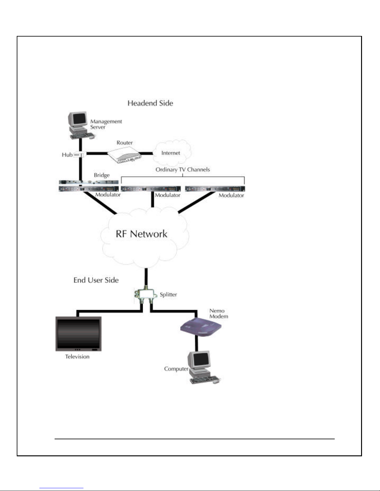
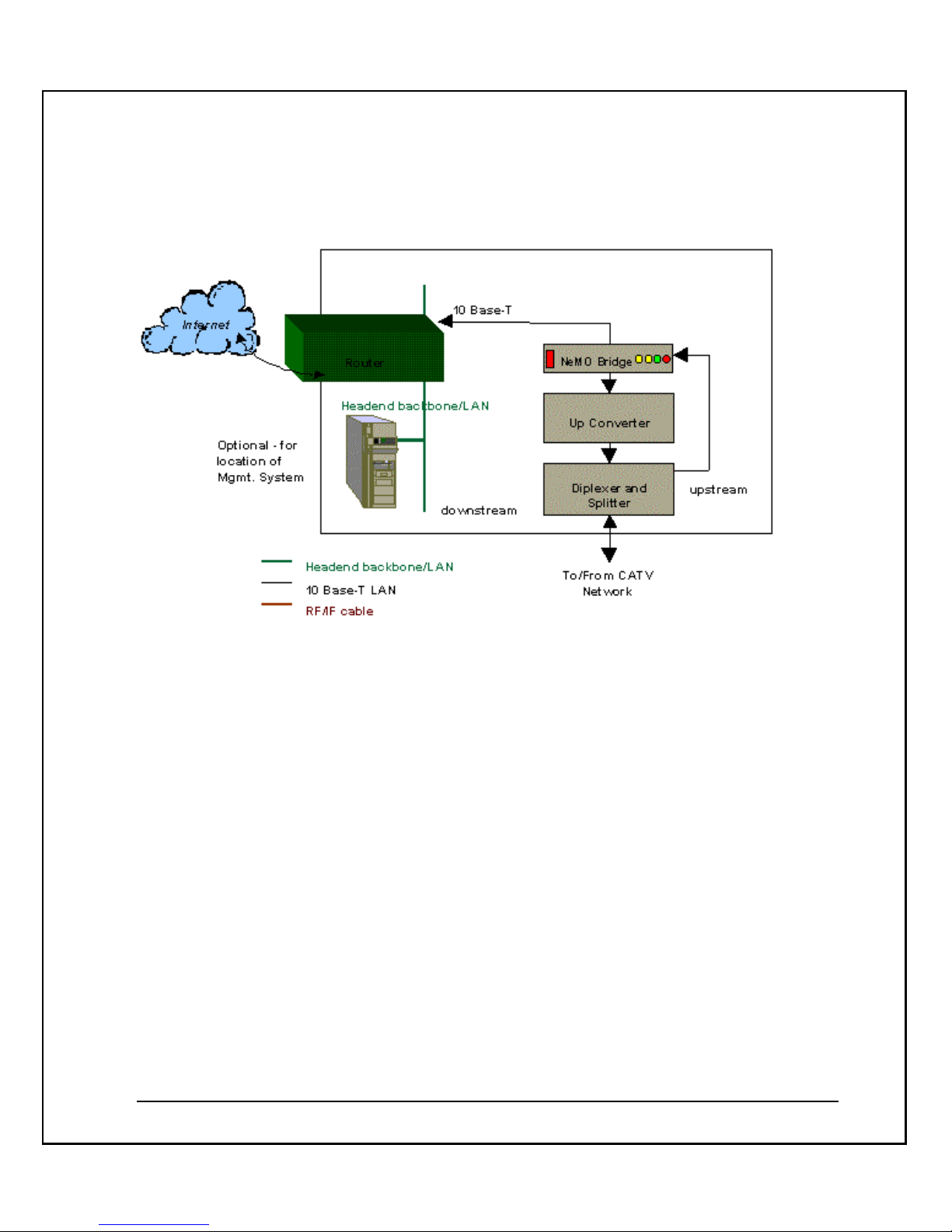
NeMo CMTS Diagram

NeMo CMTS User’s Guide
- 5 -
The NeMo CMTS diagram illustrates the following:
§ The NeMo CMTS resides at the headend site, offering access to high-speed
delivery of Internet and other on-line services to subscribers. It handles the
downstream and upstream channels. The CMTS also manages and controls the
entire network in real time. It performs real time network management functions
and controls upstream and downstream traffic intelligence.
§ The IF Agile Modulator connects to the NeMo CMTS and converts the IF input
frequency into the desired RF channel output frequency.
§ The NeMo management software resides at the headend site. It controls the
entire system in real time and off-line, and enables the system operator to
perform monitoring and management functions.
§ The NeMo modem resides at the end-user’s site providing high-speed
connectivity at speeds of up to 10Mbps via the existing cable infrastructure. It is
connected to the Ethernet board in the end-user’s computer.
o The downstream channel goes from the NeMo CMTS at the
headend site to the NeMo modem at the end-user’s site.
o The data signal (measured at back of NeMo modem) should be
10 dBmV under the video signal in the CATV. The standard
video signal is 10 dBmV, therefore the NeMo modem RF input
should be 0 dBmV. ″The splitter at the end-user’s site splits the
CATV connection. One of the splitter’s output cables is
connected to the end-user’s TV, the other cable is connected to
the NeMo modem at the end-user’s computer.
Overview
The NeMo CMTS system offers up to 10Mbps LAN access for high-speed delivery of
Internet and other online services. The remote access capability makes the NeMo CMTS
ideal for apartment complexes and high-rise residential or office buildings. The CMTS
has a bandwidth of 1.8 MHz/2.56 Mbps on the upstream and 2.8 MHz/5.12 Mbps on the
downstream. The main objective of the NeMo is to emulate an Ethernet LAN over a cable
television network and connect subscribers' computers and local servers via an IP router.
The system is comprised of an intelligent RF bridge, managed by a remote Windows NT
or UNIX workstation. The remote workstation manages all functions of authentication,
network management, subscriber database and system configuration and control, while
the NeMo CMTS distributes the Internet and other online services within the network.
The NeMo CMTS has no distance limitations. It can be placed at a node in a
neighborhood building, hotel basement or campus.
- 6 -
How the CMTS Works
The NeMo CMTS system automatically performs software downloads, utilizes constant
management messages, auto detects and keeps in memory the status of all modems in
the network, detects noise and automatically advises NeMo modems to frequency hop in
10kHz increments on the upstream. Using Elastream
TM
, the NeMo CMTS system
randomly and intelligently allocates time slots to every NeMo modem, based on demand,
priority and system resources.
The design of the NeMo CMTS originates from its simplicity, scalability and
management. With robust upstream and downstream QPSK modulation, system auto
software download, auto attenuation, upstream techniques, and remote management, it
can successfully operate in today's noisiest networks. With Elastream
TM
, Coresma's
algorithm for managing real-time network activity, an ordinary network becomes elastic,
enabling an operator to accommodate a growing number of users without creating the
urgency to upgrade.
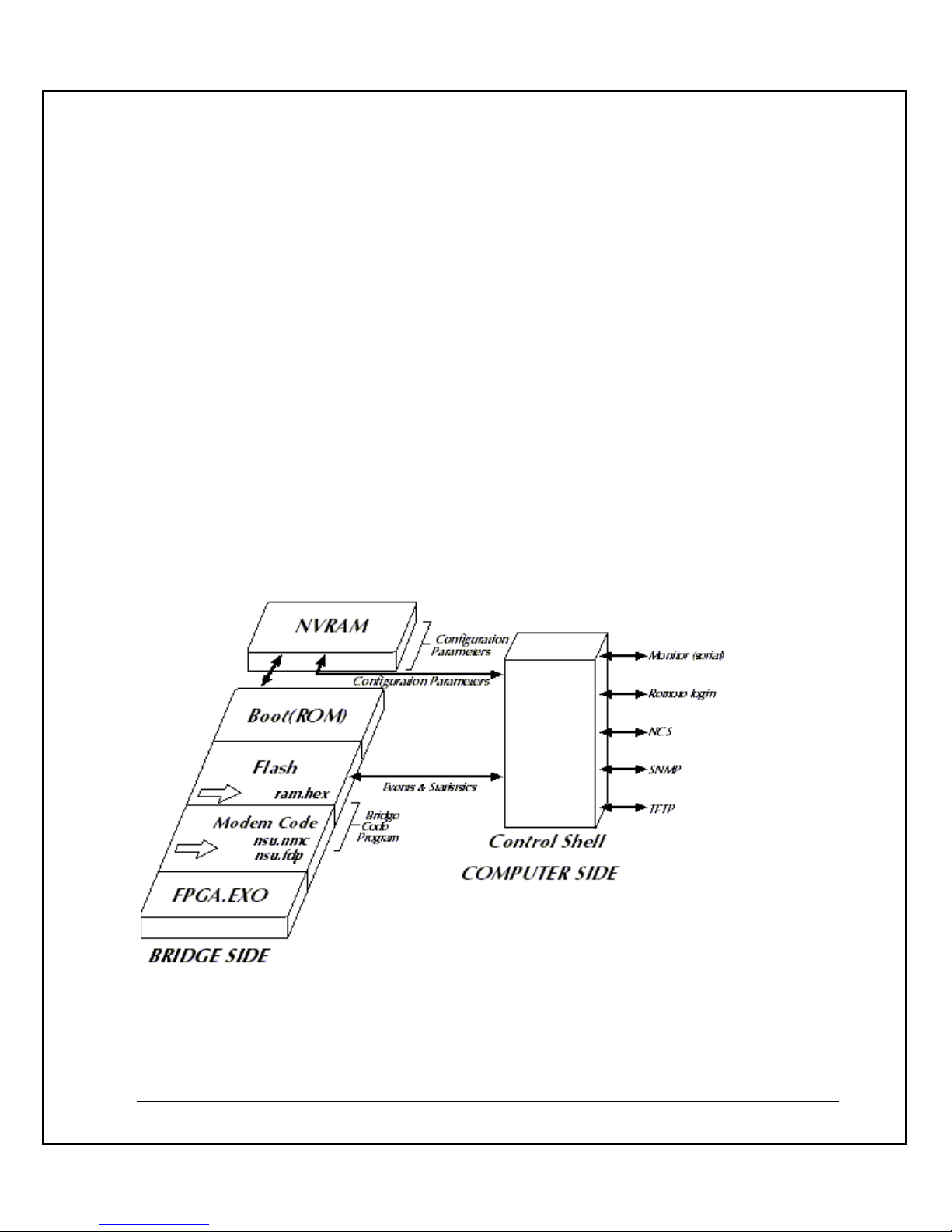
The following diagram illustrates the relationship between the NeMo CMTS and your
computer.
The CMTS contains the following:

NeMo CMTS User’s Guide
- 7 -
NVRAM Parameters: The parameters needed to configure the CMTS.
Boot (ROM): The initial code that is activated when the CMTS is turned on. The CMTS
looks to the NVRAM parameters for its configuration. It then looks for a valid boot image
(0 or 1) to determine whether to run the currently loaded software or to download new
software files from the TFTP server.
CMTS Code Program: The Flash memory contains the CMTS application (ram.hex) and
modem code (nsu.nmc, nsu.fdp).
CMTS Application: The Modem Code area stores the latest NeMo modem application
ready for download when both a new modem connects or when one with an older
software version connects.
NeMo Headend Unit
The NeMo CMTS remotely manages all NeMo modems. The CMTS tracks and monitors
the NeMo modems and network performance, collects performance and billing statistics,
enables authorization of all users, assigns QoS, runs diagnostics, initiates alarms and
downloads software upgrades.
The cable network has traditionally been a broadcast service, where the cable headend
broadcasts signals to all subscribers. The CMTS therefore broadcasts the downstream
traffic and each modem receives its appropriate data. The upstream, however, operates
on a different topology. The headend can only receive data from one modem at a tim e.
The analogy of a classroom may be used to illustrate this. The teacher (or headend) can
speak to all students (modems) at once and be understood by all. Those who choose to
listen can understand everything said and students (modems) may also choose to ignore
the teacher when the teacher does not address them (modem). The teacher (headend),
though, can only listen to one student at a time.
This architecture is flexible enough to manage varying network topologies at a cable
node. By converting a cable node to a LAN, the system can accommodate a telco return
solution at a node if required. This flexibility does not require each subscriber to tie up
their phone lines, as is the case with typical telco return solutions. The router is
configured to translate individual requests upstream via an inexpensive modem rack.
This solution can serve a building, campus, hotel, hospital or any MDU, using in-feeds
from satellite, microwave, wireless LANs or any type of DSL.

- 8 -
Configuring the CMTS
Either a serial terminal or RLogin application can be used to remotely configure the
CMTS and define its NVRAM parameters. However, first time configuration must be
performed using a serial terminal, since the RLogin connection must be done via an IP
address, and for the first time connection, the user is not familiar with the IP of the
CMTS.
Main Features
§ The NeMo CMTS converts RF to digital signals (upstream) and digital signals to
IF (downstream).
§ The RF chassis (What is the RF chassis? This is the first mention) contains signal
control for frequency and timing coordination with the headend (CMTS?).
§ The CMTS connects to one downstream modulator and one upstream
demodulator. (this is not a feature)
§ The NeMo CMTS separates the RF modules from the host (what is the host?),
which enables better signal quality.
Architecture
§ Architecture flexibility to operate using NT or Unix OS
§ Requires one CMTS and any standard router
§ Equipment installed and operational at Cable Node
§ Supports 2-way HFC, 1-way satellite (telco return), 1-way microwave or wireless,
LMDS and MMDS
Operation and Maintenance
§ Varying levels of authentication.
§ IP filtering for secure packet delivery.
§ FOCS provides a built-in subscriber database.
§ QoS offers 64kbps increments with options on data rates per subscriber.

NeMo CMTS User’s Guide
- 9 -
§ Modem's plug and surf capabilities enable system to automatically download
modem software.
§ Auto attenuation enables the headend to attenuate all modems in network.
§ SNMP management system enables diag nostics, troubleshooting, early warnings
and network alarms.
Installation Features
§ CMTS is only 1U high, 19" rack mountable, and may be installed at headend or
node.
§ Modems connect to RF and Ethernet, and may be installed by subscriber.
§ Headend broadcasts auto-connect messages to all remote modems.
§ System DHCP or static IP enabled.
Introducing the NeMo Cable Modem
NeMo is a user-friendly modem ergonomically built to suit the access needs of
subscribers. Designed to plug and play, it does not require any software installation or
attenuation pre-settings. Once connected it auto-downloads its operating software and is
fully manageable and remotely diagnosed. NeMo excels in upstream connectivity among
modems of its class. With Elastream
TM
, a real-time resource allocation algorithm, the
NeMo cable modem delivers upstream packets at a higher success ratio than modems
without such algorithms. NeMo was built to sustain connectivity to thousands of online
users simultaneously accessing Internet content.
- 10 -
System Architecture
The diagram below illustrates the system architecture:
The system consists of the following elements:
Up Converter : Converts the RF frequencies' IF input to the correct channel frequencies
output.
Diplexer and Splitter : Splits the output into multiple outputs.
Headend LAN: The LAN is the backbone of the cable network. It connects the local
server(s), the IP router and the cable network.
Note: The CMTS connects via Ethernet to the router or an Ethernet smart switch.
IP Router : enables communication from the cable network to and from the outside world
and the Internet.
NeMo CMTS. The NeMo CMTS is the RF bridge that handles downstream and upstream
termination. The CMTS consists of one downstream QPSK burst transmitter of 10Mbps
and 1 to 2 upstream burst QPSK receivers. In addition, it converts data from digital-to-

NeMo CMTS User’s Guide
- 11 -
analog and analog-to-digital. The CMTS acts as a gateway as well as system manager,
enabling IP traffic over RF, IP delivery and modem management. In addition, the CMTS
supports the RADIUS protocol for Accounting and Authentication.
The CMTS also manages and controls the entire network in real-time. It performs realtime network management functions and controls upstream and downstream traffic
intelligence. It houses Coresma's core Elastream
TM
algorithm that runs real-time system
intelligence on time slot allocation and priority scheduling. The CMTS performs the
following functions:
Media Access Control (MAC) Protocol Management. The CMTS is responsible for
upstream bandwidth allocation and downstream data forwarding. Residing in the heart
of a CATV network segment, the CMTS can receive messages from all NeMo modems
connected to its downstream channel frequency. The CMTS controls a set of one
downstream and one upstream channel.
Ethernet Bridging. The CMTS performs Ethernet bridging between the CATV network
and the CATV Ethernet backbone, which enables the usage of any Ethernet LAN
application over a CATV network.
Spectrum Management. The CMTS performs Spectrum Management system tasks and
allocates upstream and downstream frequencies to different channels. The Network
Management component also performs the tasks of Spectrum Management. It allocates
upstream and downstream frequencies to each channel. It monitors the upstream
channel quality and if necessary changes the upstream frequency if the noise threshold is
reached. In addition, it detects for collision and counters with corrective action.
TFTP Server . The TFTP server application is used to auto-update the CMTS and modem
software. The TFTP server can be installed on the CATV Ethernet backbone or anywhere
on the Internet network.
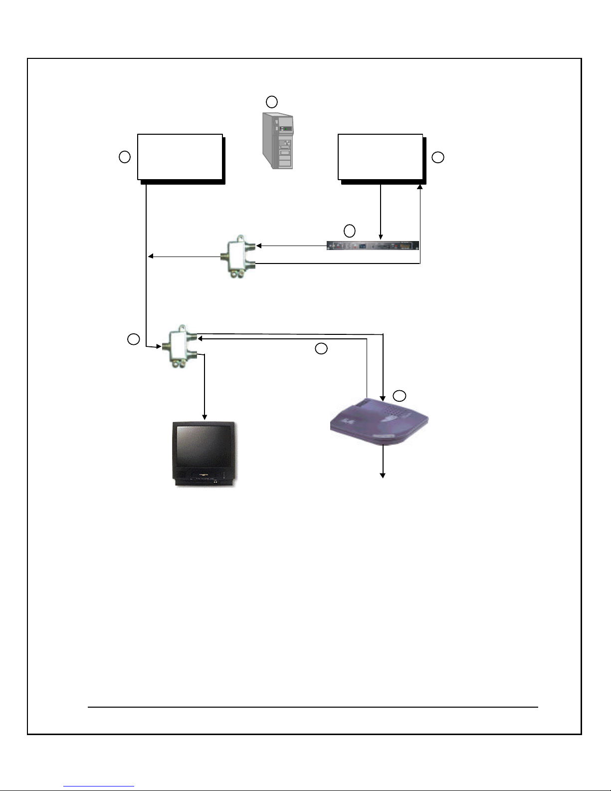
System Connectivity
The following diagram illustrates the connections and data flow of the NeMo CMTS
System.
- 12 -
CATV
NEMO
BRIDGE
Downstream
Normal
RF
Network
Do
wn
str
ea
m
Connect to the
End-user Computer
(Ethernet board)
Downstream
Upstream
1
Sp
litt
er
Sp
litt
er
Management
Software
2
3
7
5
4
6
Upstream
This diagram illustrates the following:
The NeMo CMTS resides at the headend site, offering access for high-speed delivery of
Internet and other on-line services to subscribers. It handles the downstream and
upstream termination. The CMTS also manages and controls the entire network in real
time. It performs real-time network management functions and controls upstream and
downstream traffic intelligence. The upstream connection to the NeMo CMTS from the
end-user site requires a signal power of between 0 to - 4 dBmV.
The IF Agile Modulator connects to the NeMo CMTS and converts the RF frequencies IF
input to the correct channels’ frequencies output.

NeMo CMTS User’s Guide
- 13 -
The NeMo CMTS software resides at the headend site. It controls the entire system, both
on-line and off-line and enables the system operator to perform monitoring and
management functions.
The NeMo modem resides at the end-user site providing high-speed connectivity at
speeds of up to 10Mbps via the existing cable infrastructure. It is connected to the
Ethernet board in the end-user’s computer. The upstream connection from the NeMo
modem to the splitter requires a signal power of between 30 and 57 dBmV.
The downstream channel goes from the NeMo CMTS at the headend site to the NeMo
modem at the end-user site.
At the CATV television outlet at the end-user site, the data signal (NeMo client) should
be 10 dBmV under the video signal in the CATV. The standard video signal is 10 dBmV.
Therefore, the NeMo modem RF input should be 0 dBmV.
The splitter at the end-user site splits the CATV connection. One cable is connected to the
end-user’s TV, and the other cable is connected to the NeMo modem.
Headend Hardware
The NeMo CMTS can be configured as a desktop unit on a shelf or tabletop, or it can be
placed in a 19-inch rack. The CMTS contains various LEDs, which enable it to be easily
monitored.
The following diagram displays the components of the NeMo CMTS and lists some of the
salient features:
CMTS Functionality
The CMTS translates Ethernet packet traffic into/from cable TV packets. The translation
is transparent to the adjacent router/gateway. The NeMo modem reverses the operation
of the CMTS at the end-user side. The NeMo CMTS and modem together extend an
Ethernet segment, using the CATV network as a WAN media.
RF Transmitter
The NeMo CMTS uses a QPSK modulator enabling bit rates up to 9.5 Mbit/sec, and
power levels up to 53 dBmV. The transmitter is frequency-agile between 5-45 MHz. An
external up-converter is required to position the transmitted signal into an available 6
MHz TV channel. The downstream signal power at the end-user side should be at or
around 0 dBmV.

- 14 -
RF Burst Receiver
In the CMTS, a software controlled QPSK receiver for burst transmission receives signals
in the range of 5-65 MHz, depending on the symbol rate, in the power range of –7 dBmV
up to +23dBmv for Burst QPSK Bit Rate of 2.56 Mbps and –4 dBmV up to +26dBmv for
Burst QPSK Bit Rate of 5.12 Mbps, with maximum ± 6 db burst -to-burst. The flexibility of
the receiver allows for signal optimization in noisy environments.
NeMo Modem Transmitter
A cable modem’s upstream signal level is affected by the upstream symbol rate and the
internal, software controlled attenuator. The attenuation level used can be applied in the
range of 0 to 30 dB. For example, at 15 MHz and 1.28 Meg symbol –rate (2.56 bit-rate), the
modem upstream signal level can vary between approximately 30dBmV (at 30 dB
Attenuation) and 60dBmV (at 0 dB Attenuation). Operators of HFC networks can have
sensitive equipment (e.g. lasers) that can be damaged on high levels of upstream power.
Two parameters define a ‘minimum attenuation’ for the modems. Using these
parameters operators can configure their modems to never go above a certain attenuation
level.
Channel Controller
The channel controller board runs the software and hardware managing the upstream
channel sharing, and relays information between the CATV plant and the Ethernet local
network.
IP Host Address
The CMTS has an IP host address, enabling access to the CMTS from other IP hosts. This
interface is not used for IP forwarding between CATV and Ethernet. The IP address of
the CMTS can be changed from the remote or serial shell interfaces.
Headend Software
NeMo Headend Software consists of the CMTS Embedded Code, FOCS Shared Module,
FOCS Client, and NeMo Mediator.
The NeMo Headend Software is a set of software modules that operate the cable modem
system. It enables the system operator monitor, and controls the entire system, both online and off-line. The following diagram displays the relationship between the software
components.
NeMo CMTS User’s Guide
- 15 -
CMTS Embedded Code
Two separate codes are stored in the CMTS. The first code stored in the CMTS is the
CMTS Boot Code. This code tells the CMTS how to boot and how to utilize the TFTP
protocol. The second code is the runtime code that provides the CMTS with its
functionality. There are two files that are stored in the CMTS:
ram.hex: CMTS runtime code.
nsu.fdp: Modem runtime code.
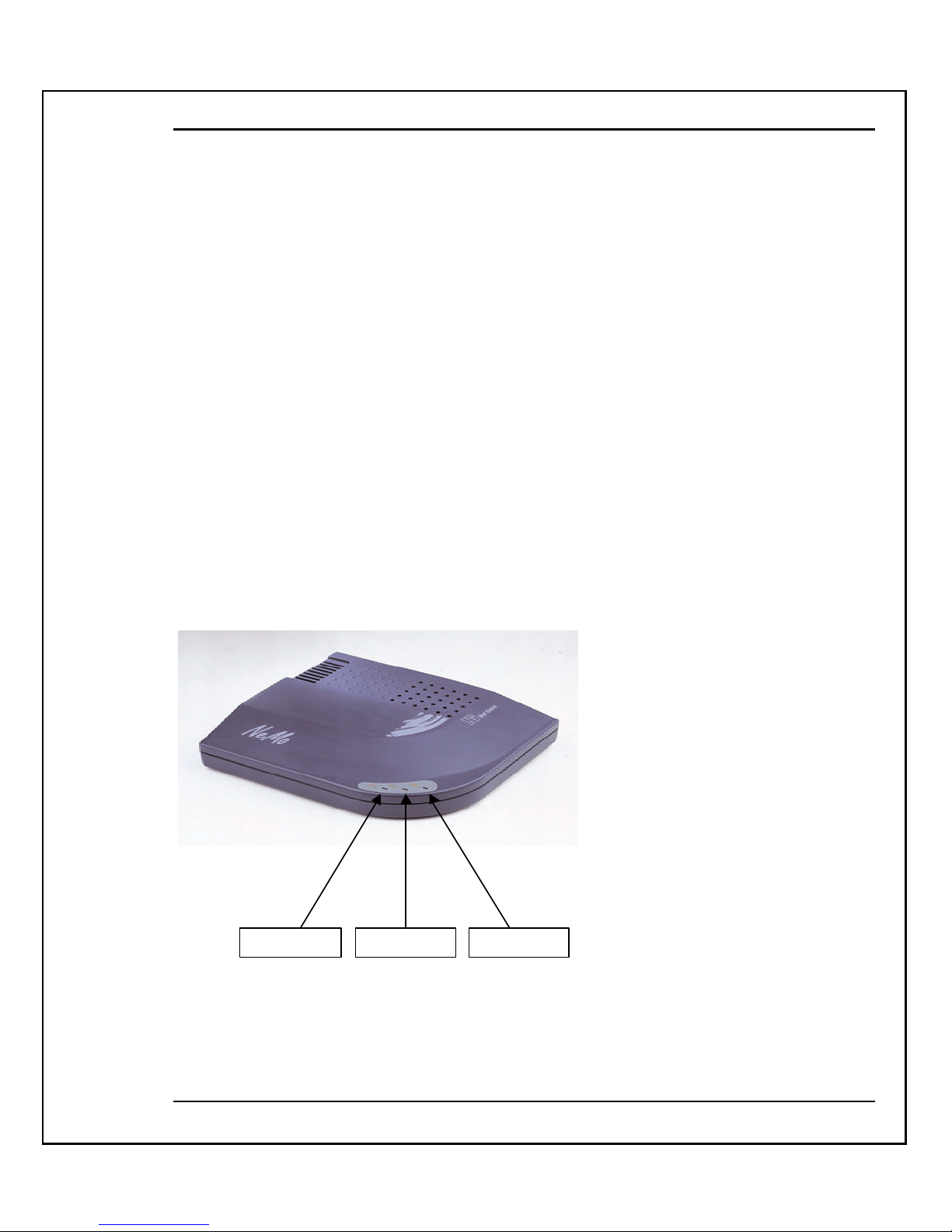
NeMo Cable Modem
The NeMo Cable Modem provides high-speed connectivity at speeds of up to 10Mbps,
via the existing cable infrastructure. With its highly intelligent upstream allocation
algorithm, noise detection trigger systems, unique Quality of Service ability, billing ready structure, and Virtual LAN services, the NeMo Cable Modem converts an HFC
cable environment into a highly flexible, elastic and network-ready service env ironment.
Data Transmit Data Receive Power
It has standard ports: Ethernet, RF and power, and an on/off switch. In addition, it has a
serial outlet for gadget expansion. It is QPSK modulated both upstream and
downstream. Downstream it uses a full 6MHz channel and upstream it can range from
1.8Mhz to 2.6Mhz. Bandwidth ranges up to Ethernet speeds of 10Mbps downstream, and
up to 5.12Mbps upstream, per modem.

- 16 -
The modem is easy to install. Once powered it initializes without any manual
intervention. It contains one ROM chip that downloads its operating software. That
software can be modified to contain features required by any cable operator. For
example, if a cable operator needs to adjust its service parameters at a later stage, the
software could be modified to address that requirement.
The NeMo Cable Modem has four main components:
§ CM Controller.
§ Burst Transmitter.
§ Downstream IF Receiver.
§ Tuner and Diplexer.
CM Controller
The Controller interfaces with the user premises via its 10Base -T Ethernet ports. It
interfaces either directly to the user PC or through a local HUB. The controller receives
downstream data from the downstream receiver and sends data to the upstream burst
transmitter. The controller is responsible for the overall control of the Tuner, Transmit
and Receive.
Burst Transmitter
The Transmitter is STANFORD TELECOM STEL-1109.
Downstream IF Receiver
The Receiver is STANFORD TELECOM STEL-2105.
Tuner and Diplexer
The Tuner and Diplexer can be monitored and controlled by the CMTool software
provided to the cable operators' technicians.
Multiple MAC Modems
The modem supports up to 4 IP address machines connected via a HUB.
Applications
The following diagrams represent possible applications for the NeMo CMTS system:

NeMo CMTS User’s Guide
- 17 -
System Without Management
RF Network
Bridge
Serial Terminal
Internet
Router
System With Management
RF Network
Remote
Bridge
Serial Terminal
Internet
HUB
Router
• Rlogin
• NCS
• OC
• Rlogin
• NCS
• OC
Management applications:
RLOGIN: Used to remotely configure the CMTS and set its NVRAM parameters.
FOCS: used to manage the CMTS and end-user's Modems.

- 18 -
CHAPTER 2
Site Preparation
This chapter discusses the various prerequisites and computer parameters to be set
before installing the NeMo CMTS.
About this chapter:
§ Overview - provides an overview of site preparation requirements
§ System Components - describes the NeMo CMTS system hardware and software
requirements
§ Basic Configuration - describes the requirements of a typical configuration
§ Preparing the Headend Site - describes the prerequisites needed to prepare the
headend site
§ Preparing a Local End-User Site - describes the prerequisites needed to test an
end-user’s system from your location.
Overview
In order to install the NeMo CMTS system, you must ensure that the environment in
which you plan to install the system contains all the necessary hardware and software
components. You will also need to prepare a management computer, prepare your RF
network, prepare a configuration drawing of the system and installation topology, and
prepare an end-user test site in your local environment.
System Components
The NeMo CMTS system comes with various component s that may differ depending on
the items you ordered. For example, a NeMo CMTS trial kit includes:
§ NeMo CMTS (1)
§ Agile Modulator (1)
§ NeMo modems (5)
§ Coresma Software CD (1)

NeMo CMTS User’s Guide
- 19 -
Open your NeMo package and check that you received the following:
§ NeMo CMTS
§ Agile Modulator (if ordered)
§ NeMo modems (amount depends on your order)
§ Power supplies
§ CMTS serial cable (female to female)
§ Coresma Software CD
§ NeMo CMTS User's Guide
Basic Configuration
The basic configuration of the NeMo CMTS syst em consists of:
§ One NeMo CMTS
§ One computer containing management software
§ NeMo modems connected through the RF network
The diagram below illustrates the relationship between the NeMo CMTS and your
computer.

- 20 -
The CMTS contains the following:
§ NVRAM parameters: The parameters needed to configure the CMTS.
§ Boot (ROM): The initial code that is activated when the CMTS is turned on. The
CMTS looks to the NVRAM parameters for its configuration. It then looks for a
valid boot image (0 or 1) to determine whether to run the currently loaded
software or to download new software files from the TFTP server.
§ CMTS Code Program: The Flash memory contains the CMTS application
(ram.hex) and modem code (nsu.nmc, nsu.fdp).
§ CMTS Application: The Modem Code area stores the latest NeMo Modem
application for download when both a new modem connects or when one with
an older software version connects.
The NeMo CMTS is configured from the computer using different protocols that enable it
to communicate with the CMTS:
§ Serial Monitor (HyperTerminal)
§ Remote Login
§ FOCS Client
§ SNMP
§ TFTP

NeMo CMTS User’s Guide
- 21 -
Each protocol can be used under different circumstances. For example, the Serial Monitor
(HyperTerminal) is used when configuring the CMTS for the first time, whereas the
FOCS is used for subsequent configurations.
Preparing the Headend Site
The headend site refers to the environment in which the NeMo CMTS syst em is to be
installed. At the headend site you must do the following:
§ Prepare the Management Computer
§ Prepare the RF Network, page 23
§ Prepare the Ethernet Network Parameters, page 25
Preparing the Management Computer
There are four services that the management computer is expected to handle when
managing the remote NeMo system. These four services are:
§ Initialization Service (Serial), page 22
§ FOCS, see FOCS Manual
§ TFTP Service, page 22
These services are usually installed on one computer, but they can be separated and
installed on as many as three separate computers. When installed on one computer, this
computer must contain the maximum number of hardware and software requirements
needed to run the management components.
Management Computer Minimum System Requirements
Hardware
§ Processor Pentium III
§ Memory 256 MB
§ Disk Space 5 GB
§ Video Card 1024 x 768 resolution
§ Network Card 10/100 Ethernet
§ Standard CD-ROM Drive

- 22 -
Software
§ Microsoft NT 4.0
o SNMP Service enabled
o Internet Information Server (IIS) enabled
o TCP/IP enabled
§ NT 4.0 Service Pack 5
§ NT 4.0 Option Pack 4
§ Microsoft SQL Server 7
§ Microsoft Internet Explorer 5
§ TFTP Server
Initialization Service
The initialization service enables you to perform first time setup of the CMTS. During the
installation and training process, this computer must be dedicated and available at all
times.
Management Service (FOCS)
The FOCS Client is a tool used for managing and monitoring the cable modem network
system. FOCS Shared Module is managed via Simple Network Management Protocol
(SNMP) and provides additional management capabilities that empower cable operators
to manipulate network parameters.
TFTP Service
The TFTP Server service enables you to upgrade the CMTS software.
The CMTS, upon request, downloads the run-time program images from a remote disk,
located on the TFTP server, using the TFTP protocol over an IP connection. The TFTP
Server can be run on Windows
TM
(NT, 95, 98) or a Unix host.
Subscribers Database Service
The Subscribers Database Service controls subscriber’s profiles and quality of service. It
uses an SQL database management module that gathers, stores and reproduces data on
subscribers, network usage and network statistics.

NeMo CMTS User’s Guide
- 23 -
Important Note: Please follow the directions below while installing the SQL Server:
§ The RPC service, SERVER service and SNMP service must be running.
§ A default printer must be installed for the Control Center reports.
§ When prompted for the master database size, enter 150 MB.
§ For inst allation options, choose Additional Network Support.
§ Select the following protocols: TCP and Named Pipes.
§ At boot time, choose Auto-start SQL Server and SQL Executive.
§ Do not enter a sa password.
§ Continue with the installation using the default settings.
§ The following messages will appear:
TCP/IP protocol installed ODBC installed!
Serial Terminal
Needed for first time configuration of the CMTS, or to recover from erroneous settings of
the CMTS. Any RS-232 capable terminal, or terminal emulation, can be used.
Rlogin Application
RLogin is a software application used to remotely manage the CMTS configuration
(NVRAM parameters).
Remote Control Center
The Control Center is the interface that enables the user to locally or remotely manage
the database.
Cables
§ Coaxial-F cables to connect the NeMo modem to the RF plant.
§ Attenuators to adjust RF signal level.
§ 10 Base -T cables to connect the CMTS to the Router or LAN
Preparing the RF Network
After the management computer has been prepared, you can make your RF network
compatible with the NeMo CMTS system. This section assumes that your cable network

- 24 -
is capable of two-way communication, supporting both upstream (return cable) and
downstream communication.
In order to prepare the RF network, it is necessary to determine the following factors:
§ Channel Frequencies and Attenuation Level , page 24.
§ IF/RF Agile Modulator Support, page 24.
§ Spectrum Analyzer Support, page 24.
§ Fixed Value Attenuators, page 25.
Channel Frequencies and Attenuation Level
The NeMo CMTS requires certain minimum channel frequencies. Please check the
following:
§ The frequency downstream to be used (minimum 150 MHz).
§ The frequency upstream to be used (4 channels between 5MHz to 42MHz. The
recommended frequency is 15MHz to 30MHz.)
§ The attenuation of the entire cable network, both upstream and downstream
channels.
IF/RF Agile Modulator Support
An Agile Modulator Up Converter is required to transform signals from the IF range to
the RF range. The Agile Modulator should support European (PAL) and US (NTSC)
signals. The Modulator specs must then be faxed to Coresma for approval. See Chapter 4,
Contacting Coresma.
Spectrum Analyzer Support
A Spectrum Analyzer is a device commonly used for measuring the RF network during
installation and adjusting the RF sequence. Make sure that your Spectrum Analyzer
supports frequencies between 5-600MHz, average and maximum measurements, and
spectrum and maximum hold.
In addition, please make sure you have the following:
§ spectrum analyzer documentation
§ an engineer familiar with the operation of the Spectrum Analyzer

NeMo CMTS User’s Guide
- 25 -
§ an F connector for the IF inlet
Fixed Value Attenuators
When installing the NeMo CMTS system, it is necessary to have fixed value attenuators
on your site that can reduce the signal level. The following attenuators are required:
20 dB 3 attenuators
16 dB 3 attenuators
10 dB 3 attenuators
6 dB 3 attenuators
3 dB 4 attenuators
Preparing the Ethernet Network Parameters
Ethernet network parameters refer to the network parameters located at the headend site.
To setup this aspect of the site, you must obtain the following information:
§ Internet Router Information, below.
§ Ethernet Network Checklist, page 26.
Internet Router Information
An Internet router is needed for layer 3 routing of IP packets between the NeMo CMTS
and the Internet. The router is also required in case the TFTP server is located in an IP
segment that is different from the segment of the CMTS. Ensure that you have the
following inf ormation about your Internet router:
§ The IP address of your router
§ DNS server IP address
o You can use fixed or static IP addresses - (addresses you
permanently assign to clients)
or
o A DHCP server which enables a server to dynamically assign IP
addresses to your clients when they connect

- 26 -
§ IP Pool Range. If you are using a DHCP server, you must request a pool range
from your Internet Service Provider based on the number of customers you are
serving.
§ Subnet Mask
§ Internet connection type and line speed
Ethernet Network Checklist
The following must be on site and operational before installing and operating the NeMo
CMTS:
§ An available 10BaseT Ethernet HUB
§ Computers (management/server) that have working network cards with proper
drivers to enable the Ethernet connection
To make sure you have an operative Ethernet connection:
§ Connect the management computer to the hub and router and make sure that
the management computer has access to the Internet. A successful connection
determines the following:
o The router is operative
o You have a connection to the Internet
o The HUB is operative
o The network card in Windows NT is operational
Preparing a Local End-User Site
As part of the installation process you will prepare a local, end-user test site at your
location. This process will allow you to ensure that the NeMo CMTS system that you
installed is operational. A computer with the following hardware and software is
required:
Hardware
§ Processor Pentium 133MHz
§ Memory 64 MB
§ Disk Space 1 GB
§ Video Car d 1024 x 768 resolution

NeMo CMTS User’s Guide
- 27 -
§ Network Card 10/100 Ethernet
§ CD-ROM Drive Standard
Software
§ Microsoft Windows 98 SE, 2000
§ Microsoft Internet Explorer 5
Make sure that this computer is connected to an operational network card with proper
drivers to enable the Ethe rnet connection. Refer to the section Ethernet Network Checklist
on page 26, for instructions on how to test if you have an active Internet connection.
Installation Configuration
In order for the Coresma engineer to prepare for the installation process, please answer
the questions and sketch the diagrams described in the Setup Questionnaire on the next
page and email or fax the requested information to Coresma. Refer to Chapter 4,
Contacting Coresma, for contacting instructions.
Set-Up Questionnaire
§ Is the installation going to take place on a closed system at the headend for
demonstration purposes only? (will only a simulat ed RF network be involved)?
§ Is the installation going to take place on a live RF/HFC Network?
§ How many modems do you plan to install in your initial configuration?
Prepare a system and installation drawing of the configuration planned for the
installation of the NeMo CMTS system. In addition to the drawing, the following
information should be included:
§ The IP address of the CMTS
§ The distribution of services of the management computer
§ Where the management computer will be located
§ Which router will be used
§ Whether you want the CMTS and management to be on the same or different
subnet from the clients.


NeMo CMTS User’s Guide
- 29 -
CHAPTER 3
Installing the NeMo CMTS
Chapter 2 described site preparation for the NeMo CMTS in a typical configuration. This
chapter tak es you through the installation process in a typical configuration. If you have
any questions about your particular installation, please refer to Chapter 4, Contacting
Coresma.
About this Chapter
§ Part 1: Setting Up the CMTS and Modulator Connection, page 29, describes
how to set up the CMTS and modulator and connect it to the RF network.
§ Part 2: Setting Up the Management Computer(s), page 35, describes how to
configure the CMTS using HyperTerminal, TFTP, and FOCS
§ Part 3: Setting Up an End-User Site, page 41, describes how to install the NeMo
Modem and set up an end-user test site at your location.
Part 1: Setting Up the CMTS and Modulator
Connection
The first part of the installation process is to set up the NeMo CMTS and modulator. This
requires the following steps:
§ Connecting the CMTS and the Modulator
§ Calibrating the RF Signals and Connecting to the RF Network, page 31
Connecting the CMTS and Modulator
To install the NeMo CMTS and modulator, the following steps are required:
1. Attaching the CMTS and Modulator
2. Connecting the RF Cable to the CMTS
For this step you will need:

- 30 -
§ One NeMo CMTS
§ One agile modulator
§ Four RF cables
§ Attenuators (at least 20 dBmV)
Step 1. Attaching the CMTS and Modulator
Attach the CMTS and modulator to a standard 19" rack or place them on your desktop.
Make sure to leave a distance of at least 1U between them.
Step 2. Connecting the RF cable to the CMTS
The next step is to connect the RF cable to the CMTS.
Rear Panel View
Power
Data
RF InMonitor EthernetIF Out
Maint.
P.C. Hub
The following describes the connectors that appear on the rear panel of the CMTS.
Maintenance P.C./Hub: 10Base -T connector (to be used by trained maintenance personal
only)
IF Out: F-Connector. The downstream data output from the CMTS modulated on an IF
frequency
Data/Monitor: DB9 connector port for serial terminal
Data/Ethernet: 10Base-T connector for Ethernet connection
RF In: F-Connector - The RF upstream data input to the CMTS
Power: 110 - 220 Volt at 50 - 60 Hz
To connect the RF cable to the CMTS:
1. Take one RF cable and connect it to the IF Out (low range) outlet on the CMTS.
2. Take the other end of the cable and attenuate the signal by attaching
approximately 20 dBmV of attenuators to the cable.

NeMo CMTS User’s Guide
- 31 -
2 Note: The attenuation process ensures that the modulator receives the
appropriate signal. The modulator should receive a signal of 8 - 15 dBmV. The
CMTS gives out the following signals:
PAL: 36.15 MHz in 30 dBmV
NTSC: 43.5 MHz in 30 dBmV
3. Take the end of the RF cable with the attenuators and connect it to the IF IN
outlet in the modulator.
4. Take another RF cable and connect it to the RF OUT outlet on the modulator.
Leave the other end of the cable disconnected. This will be used for the
downstream channel.
5. Take another RF cable and connect it to the RF IN outlet on the CMTS. Leave the
other end of the cable disconnected. This will be use d for the upstream channel.
Calibrating the RF Signals and Connecting to the RF
Network
Once you have attached the CMTS and modulator, you are ready to calibrate the RF
signals and then connect the CMTS to the RF network. To adjust the power level of the
signal, the following steps are required:
1. Attenuating the Downstream Signal
2. Attenuating the Upstream Signal
3. Connecting to the RF Network, page 35
Before starting this procedure, ensure the following:
§ The CMTS power is turned ON.
§ The modulator power is turned ON.
§ The spectrum analyzer is available.
Step 1: Attenuating the Downstream Signal .
The downstream signal should reach the modem at 0 dBmV. When you attenuate the
downstream signal, it is necessary to take into account all the splitters that are used
according to their attenuation levels (the attenuation level is usually indicated on the
splitter).

- 32 -
To attenuate the Downstream Signal:
1. Connect the downstream cable to the RF -OUT connector on the modulator.
2. Establish a serial connection between the CMTS and your computer, through the
COM 1 or COM 2 port using a serial cable.
3. You will need to use HyperTerminal to connect using the serial connections as
well. To do this
i. Open HyperTerminal from the START menu.
ii. When prompted for a name, type in “NeMo” and hit return.
iii. HyperTerminal will ask for the details of the phone number you wish to
dial.
iv. Tab down to the “Connect Using:” block and select COM1 or COM2
from the pull down menu depending on which port your serial cable is
attached.
v. Click “OK”.
vi. In the “Bits per second:” field, enter 38400.
vii. Ensure that the “Data bits”, “Parity”, and “Stop bits” are “8”, “None”,
and “1” respectively.
viii. Select “None” from the “Flow cont rol” field and click on “OK”.
ix. A window will open and the CMTS will begin scrolling text displaying
the boot sequence and software versions. These versions may have to be
upgraded using the included CD later in the installation.
4. After the boot sequence has completed, hit the return key and a >Boot prompt
should appear. To begin the configuration process of the CMTS, please refer to
section 3-15.
5. Ensure the CMTS downstream frequency is set to 43.5 MHz if you are using an
analog agile modulator, and 44MHz if you are using a digital agile modulator.
6. Select an appropriate modulator channel.
7. Connect the spectrum analyzer to the IF-OUT connector on the CMTS, and
ensure proper signal shape and level readings on the analyzer

NeMo CMTS User’s Guide
- 33 -
8. Disconnect the spectrum analyzer and connect the IF-OUT connector on the
CMTS to the IF-IN connector on the modulator.
9. Connect the spectrum analyzer to the RF -OUT connector on the modulator, and
ensure proper signal shape and level readings on the analyzer, (with a minimum
SNR of 20dB).
10. Identify any video carrier signals on neighboring channels and ensure that the
carrier signal on the CMTS is at least 10dB less than the video carrier signal.
11. Connect the RF test point (where the client computer will connect), to the
spectrum analyzer, using the test point cable, and ensure proper downstream
signal shape and level readings on the analyzer, (with a minimum SNR of 20dB).
12. Connect the test point cable to the modem, and then activate the modem.
13. Use the NeMoTool on the client computer to burn in the correct downstream
frequency and to set the bit-rate, as described on page 3-26.
2 Note: Ensure that the modem is locked on the downstream frequency, and that
the FDP process is completed.
14. On the NeMoTool, select Consul and verify that the modem has achieved 0
attenuation.
When attenuating the downstream channel:
§ The CMTS and modulator must be powered ON.

- 34 -
§ Determine which RF frequency is coming out of the modulator by referring to
the modulator channel chart. You will need to add 2.75 in PAL and 1.75 in NTSC
to the number that you have in order to reach the center of the signal. This will
be burned into the modem, as described on page 31. This number will be the
frequency that you checked in the Spectrum Analyzer when checking the
downstream signal.
§ The downstream signal power in this frequency should be 0.
Step 2: Attenuating the Upstream Signal
Attenuation of the upstream signal is essential if the CMTS is to function as intended.
The modem transmits in the 30-60 dBmV range, and the CMTS should get its upstream
signal at 0 dBmV. Therefore, attenuate the signal as described below.
Note: Even in a worst -case scenario, the CMTS will not process a signal in excess of 25
dBmV.
To attenuate the Upstream Signal:
1. Locate the signal generator.
2. Connect the signal generator to the test point.
3. Connect the spectrum analyzer to the upstream cable on the CMTS side.
4. Obtain the level of the signal generator signal strength and calculate the
attenuation on the upstream through the RF network
5. Calculate attenuation to protect the safety of the burst receiver in case of extreme
situations such a signal level fluctuation. For example, if your signal generator
output is +50 dBmV, and your spectrum analyzer reads +38 dBmV, there is 12
dBmV of loss on the upstream of the RF plant. Ideally, your modem will
transmit at +45 dBmV. To ensure optimal operation, the upstream signal should
reach the CMTS at +0 dBmV. From our measurement, we can calculate the
required amount of fixed attenuation required on the IF input of the CMTS.
Below is an example:
Ideal Modem upstream transmit level +45 dBmV
Upstream signal loss through RF plant 12 dBmV
Required amount of fixed attenuation 33 dBmV
6. Using the spectrum analyzer, obtain the noise level on the upstream frequency
chosen.
2 Note: The recommended initial attenuation setting is 30dB.

NeMo CMTS User’s Guide
- 35 -
7. Select upstream channel attenuation.
8. Connect the upstream signal to the RF -In connector on the CMTS
9. Reset the modem and ensure that the modem attenuation locks on the
appropriate and pre-calculated attenuation number from Step 5. of Section 3-6.
10. Ping the management computer.
11. Ensure a steady connection and speed, and adjust the upstream burst receiver
input window to be as narrow as possible while still allowing all modems to
connect to the CMTS
2 Note: If the modem locks and displays OK using an unexpected attenuation,
this is a false positive value. You must stop and recalculate the attenuation
number until the display value is appropriate.
Calibrate the upstream and signal level parameters to provide optimal performance.
Step 3. Connecting to the RF Network.
After you have attenuated both the upstream and the downstream signals, connect both
cables to a two-way splitter, as follows:
1. Take the two RF cables with attenuators at the unconnected end and attach them
to the two-way splitter.
2. Connect another RF cable to the single outlet on the two-way splitter. This cable
will connect through the RF network to your clients.
Part 2. Setting Up the Management
Computer(s)
The next part of the installation procedure is to set up the management computer,
enabling first time CMTS setup and operation. The management computer needs specific
software in order to configure and maintain the CMTS. This includes:
§ TFTP Server : Enables you to auto-update the CMTS and modem software.
§ FOCS: enables the system operator to monitor and control the NeMo CMTS
system, both online and offline.
Setting up the management computer consists of the following stages:
§ Configuring the CMTS for the First Time
§ Configuring the CMTS Using FOCS page 40

- 36 -
Configuring the CMTS for the First Time: CMTS
Configuration
First time configuration of the CMTS must be done using the HyperTerminal in order to
connect the CMTS, management computer and router. Subsequent configurations of the
CMTS can be done more easily using the FOCS as described in the next section.
The following steps are required:
1. Connecting the CMTS to the Management Computer
2. Configuring the CMTS
3. Setting up the TFTP Server
Before you begin, ensure the following:
§ Your management computer is on and a serial port is available (for example
COM1 or COM2)
§ The CMTS power is turned OFF
§ Your management computer has HyperTerminal installed
Step 1. Connecting the CMTS to the Management Computer.
1. Connect the serial cable to the CMTS, as follows:
2. Connect one end of the serial cable to the available PC COM port.
3. Connect the other end of the serial cable to the CMTS MONITOR outlet.
4. Open the HyperTerminal application on your management computer and
establish the connection by first entering a connection name, then entering the
COM port you will be using.
5. After this is completed, the COM Properties dialog box is displayed. Enter the
parameters shown below:

NeMo CMTS User’s Guide
- 37 -
You are now ready to connect the CMTS to the management computer and router.
Step 2. Configuring the CMTS.
1. Turn the CMTS power ON. At this point you should see some activity in the
HyperTerminal. After this activity stops, you will see the Boot> prompt and
the following window will be displayed:

- 38 -
This shell enables you to accurately input first time data into your CMTS.
2. Type Help and press <Enter>. A list of the available commands is displayed, as
shown in the example below:

NeMo CMTS User’s Guide
- 39 -
Next, you will set a few parameters for the CMTS to connect to the management
computer and load runtime files.
3. Type Show and press <Enter> to view the NVRAM variables, which enable you
to verify the configuration parameters, as shown below:
In order to change a parameter, the following syntax is required:
4. set <parameter name > <new parameter>
2 Note: Remember to use lower case letters.
5. Next, set the CMTS IP parameters. This includes the IP address, Netmask and
Gateway, as follows:
set ipaddr xxx.xxx.xxx.xxx The IP address of the CMTS.
set netmask xxx.xxx.xxx.xxx Your network Netmask.
set gateway xxx.xxx.xxx.xxx This is usually the IP address of
your router.
You are now ready to install and setup the TFTP server. When you setup the TFTP server,
minimize the HyperTerminal screen (do not close the session).

- 40 -
Step 3. Setting up the TFTP Server
The TFTP server application enables you to auto-update the CMTS and modem software.
It downloads the following files: ram.hex, nsu.nmc and nsu.fdp. The TFTP server
application is installed from your Coresma Software CD.
1. Follow the installation instructions on the CD in order to install the TFTP server.
2. Return to the HyperTerminal session, and type the following:
set tftpserver xxx.xxx.xxx.xxx The IP address of the server on
which you just installed TFTP.
set tftppath Disk location of the new version
files.
3. In order for the CMTS to start functioning, it must load its runtime files (located
in the TFTP directory you installed). To do so, type:
set validbootimage 0 This enables the CMTS to
download its runtime files from
the TFTP server.
4. Reboot the CMTS by typing: reboot, then press <Enter>
The CMTS will now start loading the runtime files for RUNNING. This action may
take up to one minute.
2 Note: The last number that appears after the download is completed is the
MAC address of the gateway of the CMTS. If the number is all zeros this
means that the CMTS has an incorrect gateway address.
5. After this process is completed, you will see the CMTS> prompt in the
HyperTerminal. Type Show, then press <Enter> to see the new changed values.
You are now ready to configure the CMTS using FOCS; the Coresma SNMP based
application for user-friendly configuration.
Configuring the CMTS Using FOCS
The FOCS controls and monitors the online operation of the CMTS. As part of the initial
installation process, you will need to install and configure the FOCS. It is installed from
the Coresma Software CD, on the same computer that the TFTP server is installed. After
you setup the CMTS the first time using HyperTerminal, you will use FOCS Client for all
future contact with the NeMo CMTS system. Please refer to the FOCS, manual for further
instruction.

NeMo CMTS User’s Guide
- 41 -
Part 3: Setting Up an End-User Site
After you have successfully completed setting up the headend site, you are ready to
connect the NeMo modem to an end-user’s computer and setup an end-user test site.
This test is usually performed using a dedicated computer at your location.
Setting up an end-user site consists of the following stages:
Before You Begin, page 41
Installing the NeMo Modem, page 41
Installing and Using the NeMo Tool, page 42
Before You Begin
Before you confirm the NeMo modem is functional at an end-user site, you must
perform the following tasks at the headend and end-user sites:
Headend Site
§ Confirm the CMTS is powered ON.
§ Confirm the Network is connected to the CMTS.
§ Confirm the RF wiring is attached and assembled correctly.
End-User Site
§ Turn the end-user PC ON.
§ Make sure that the Ethernet card is operational and has an IP address.
§ Connect the NeMo modem to the Ethernet card and RF network, as described in
the next section.
Installing the NeMo Modem
The NeMo cable modem enables high-speed connectivity at speeds of up to 10Mbps, via
the existing cable infrastructure. The NeMo modem is easy to install and configure.
The connections on the rear panel of the NeMo modem include:
§ Off/On Switch
§ 5VDc: Input power plug

- 42 -
§ Computer: 10 Base -T connection to the end-user’s computer (LAN board)
§ CATV: RF connection that connects to the TV cable
To install the NeMo modem :
1. Connect the power supply to the 5 VDC inlet.
2 Note: Ensure that the power supply is installed near the modem and easily
accessible.
2. Connect one end of a RJ45 cable to the computer port.
3. Connect the other end of the RJ45 cable to the Ethernet card in your PC.
4. Connect one end of the RF cable to the CATV outlet on the modem.
5. Connect the other end of the RF cable to the CATV inlet or the RF splitter.
Installing and Using the NeMo Tool
The NeMo Tool is located on the Coresma Software CD and enables you to configure the
modem with the correct frequency information necessary to contact the CMTS.
To install the NeMo Tool:
1. Turn the NeMo modem ON.

NeMo CMTS User’s Guide
- 43 -
2. On the end-user computer, install the NeMo Tool by opening the folder named
NeMo tool and clicking on the setup.exe file.
To use the NeMo Tool:
1. Open the NeMo Tool . The NeMoTool dialog box is displayed:
2 For a complete description of the tab options available in the NeMo Tool, refer
to the Chapter XX.
2. Click on the Advanced tab. The following window is displayed:

- 44 -
3. In the Downstream Channels Table, fill out the following information in the
fields provided:
§ Label: Enter the name of the downstream channel
§ Frequency (MHz): Enter the frequency of the downstream channel
§ Bit Rate (MBit/sec): Enter the bit rate of the downstream channel
4. Click . After a few seconds, the following occurs:
§ The green light on the modem starts blinking quickly.
§ The orange light on the modem starts blinking slowly.
This is the lock on frequency and runtime software download procedure and should
take approximately 45 seconds.
5. When the preceding procedure is completed, click the Tuner tab. The following
window is displayed:
I
6. In this window, make sure that the frequencies you have chosen are correct.
7. Now that the modem is successfully connected to the system, try to ping the
server.
Congratulations, you have just successfully installed your NeMo CMTS system!

NeMo CMTS User’s Guide
- 45 -
APPENDIX A
RLogin
Commands
This appendix describes the functionality of the Rlogin commands and contains the
following main sections:
Introduction (page 45)
Shell Commands (page 46)
Control Variables (page 47)
Introduction
The NeMo CMTS maintains the control and status information that is available and
accessible by the administrator. For example, the NeMo CMTS maintains statistics on the
incoming and outgoing traffic, current upstream and downstream frequencies and
symbol rates, IP address, subnet mask, gateway address, and so forth. The management
information is stored in the NeMo CMTS control variables.
Directories are used to group variables by their purpose, under a single name. For
example, the downchan directory includes variables for changing and viewing the
downstream frequency and symbol rate.
The NeMo CMTS RLogin Shell displays a Bridge> prompt when it is waiting for you
to enter a command. (The actual text depends on the current directory).
Requirements
Any RLogin client program can be used.
Authorization
After the connection has been established, you will be prompted for the username and
password.

- 46 -
Rlogin Password
When using Rlogin client to connect to the CMTS, both User Name and Password entries
must be entered. The User Name must be "Admin"; the password is configurable. The
default is "Admin". Refer to Cmts directory on page 52 for instructions on Rlogin
password configuration.
The following is a list of the RLogin commands that are available in the root directory.
Shell Commands
There are nine shell commands that are described below:
dir
Purpose: Display information about variables and subdirectories.
Format: dir
cd
Purpose: Change the current directory.
Format: cd <directory>
Examples: cd downchan - change the current directory to downchan.
cd .. - go up one level
cd / - go to the ROOT directory
show
Purpose: Display the status of the variable.
Format: show [variable][id]
Note: Without arguments will display the values of all variables in the current directory.
id - for the service variables indicates the client's side.
set
Purpose: Sets the variable to required value.
Format: set <variable> <value>
help
Purpose: Display detailed information about a command.
Format: help [command]

NeMo CMTS User’s Guide
- 47 -
Note: Without arguments will display a list of all available commands.
quit
Purpose: Terminate rlogin session.
Format: quit
reboot
Purpose: Causes the NeMo CMTS's boot ROM to restart the boot sequence.
Format: reboot
write
Purpose: Store the NVRam data.
Format: write
ls
Purpose: See dir.
Format: ls
Control Variables
Root directory
mac_address
Description: CMTS's Ethernet address.
Access: Read, Write
Example: Bridge> show mac_address
Bridge> set mac_address 00-AA-00-10-20-30
up_time
Description: Bridge running time.
Access: Read
Example: Bridge> show up_time

- 48 -
software_version
Description: Software version of the currently running program image.
Access: Read
Example: Bridge> show software_version
fdp_version
Description: Software version of the modem.
Access: Read
Example: Bridge> show fdp_version
Service directory
total_data_slots
Description: Total number of slots used by the given sid.
Access: Read
Example: Bridge\service> show total_data_slots 5
total_data_grants
Description: Total number of slots given to the sid.
Access: Read
Example: Bridge\service> show total_data_grants 5
cm_address
Description: Modem's mac address.
Access: Read
Example: Bridge\service> show cm_address 5
create_time
Description: The bridge uptime in seconds when the SID joined.
Access: Read
Example: Bridge\service> show create_time 5
admin_status
Description: The st atus for the sid. 1: operating, 3: destroyed 4: reset.
Access: Read, Write
Note: Set to 3 to destroy an operating SID.
Example: Bridge\service> show admin_status 5
Bridge\service> set admin_status 5 3
Bridge\service> set admin_status 5 4

NeMo CMTS User’s Guide
- 49 -
Upchan directory
slot_size
Description: Data slot size (in time ticks).
Access: Read, Write
Valid values: 8-10
Example: Bridge\upchan> show slot_size
Bridge\upchan> set slot_size 9
symbol_rate
Description: Upstream symbol rate. Accepted values:
Access: Read, Write
Valid values: 0 for 2.56Mb/s, 1 for 5.12Mb/s.
Example: Bridge\upchan> show symbol_rate
Bridge\upchan> set symbol_rate 0
Frequency
Description: Upstream frequency.
Access: Read, Write
Valid values: Accepted values 5-42MHz in units of 10kHz.
Example: Bridge\upchan> show frequency
Bridge\upchan> set frequency 3200 (32MHz)
avr_cnr
Description: Average Carrier to Noise Ratio.
Access: Read
Example: Bridge\upchan> show avr_cnr
signal_wnd_center
Description: Modems ar e allowed to join the Remote Bridge only at a certain signal
level. This signal level has a lower and upper limit. The difference between those
limits is called an allowed signal level window. The signal_wnd_center is the median
of the upper and lower limits.
Valid values: 0 to 18 dBmV.
Access: Read, Write
Example: Bridge\upchan> show signal_wnd_center
Bridge\upchan> set signal_wnd_center 0
signal_wnd_size
Description: Modems are allowed to join the Remote Bridge only at a certain signal
level. This signal level has a lower and upper limit. The difference between those

- 50 -
limits is called an allowed signal level window. The signal_wnd_size is half the
difference between the upper and lower limits.
Valid values: 2 to 6 dB.
Access: Read, Write
Example: Bridge\upchan> show signal_wnd_size
Bridge\upchan> set signal_wnd_size 2
min_attn_lvl
Description: Cable modems upstream signal level is affected by the upstream symbol
rate and the internal - software controlled attenuator. The attenuation level used can
be applied in the range of 0 to 30 dB. For example At 15 MHz and 1.28 Meg symbol-
rate (2.56 bit-rate) the modem upstream signal level can vary between approximately
30dBmV (at 30 dB Attenuation) and 60dBmV (at 0 dB Attenuation). Operators of
HFC networks can have sensitive equipment (e.g. lasers) that can be damaged on
high levels of upstream power. Two parameters define a ‘minimum attenuation’ for
the modems. Using these parameters operators can configure their modems to ‘never
go above’ a certain level. For example setting the min_attn_lvl parameter to 5 will
cause the modems to attenuate at least 10 dB. This will cause, for the previous
example details, the modem range to be between approximately 30dBmV (at 30 dB
Attenuation) and Maximum 50dBmV (using the minimum - 10dB Attenuation).
Configuration is valid only from serial/Rlogin shells.
Note: Values must be entered for both NeMo and NeMoE modem types. Different values
can be used since RF modules are a bit different between the modem types. Default
value for minimum attenuation levels is 0.
Valid values: 0 to 14 dB at 2dB per unit. A value of 10 prevents the modems from
attenuation levels less than 20 dB.
Access: Read, Write
Example: Bridge\upchan> show min_attn_lvl
Bridge\upchan> set min_attn_lvl 2
min_attn_lvl_e
Description: See description for min_attn_lvl.
Valid values: 0 to 14 dB.
Access: Read, Write
Example: Bridge\upchan> show min_attn_lvl
Bridge\upchan> set min_attn_lvl 2
use_frame_correction
Description: Set to 0 to disable frame correction for this upstream. Set to
1 to enable.
Access: Read, Write
Example: Bridge\upchan> show use_frame_correction
Bridge\upchan> set use_frame_correction 1

NeMo CMTS User’s Guide
- 51 -
burst_length
Description: Burst length in symbols.
Access: Read, Write
Example: Bridge\upchan> show burst_length
Bridge\upchan> set burst_length 1028
frame_corr_thresh
Description: If upstream error percentage is larger than this threshold then upstream
error correction is enabled. When this value is 0, upstream error correction is always
enabled, when 100, upstream error correction is always disabled.
Access: Read, Write
Valid values: 0-100
Example: Bridge\upchan> show frame_corr_thresh
Bridge\upchan> set frame_corr_thresh 50
Freq_hopp_table directory
hopp_freq
Description: Frequencies for frequency hopping table
Access: Read, Write
Valid values: 5000000 – 42000000
Example: Bridge\upchan> show hopp_freq 1
Bridge\upchan> set hopp_freq 2 5100000
Downchan directory
tx_power
Description: Attenuation strength (0 = full power)
Access: Read, Write
Valid values: 0 – 15
Example: Bridge\downchan> show tx_power
Bridge\downchan> set tx_power 0
freq
Description: Downstream frequency.
Access: Read, Write
Valid values: 60KHz - 900MHz in increments of 10kHz.
Example: Bridge\downchan> show freq
Bridge\downchan> set freq 5000

- 52 -
spectrum_inversion
Description: Spectrum inversion
Access: Read, Write
Valid values: 0 – 3
Example: Bridge\downchan> set spectrum_inversion 3
Bridge\downchan> show spectrum_inversion
sym_rate
Description: Downstream symbol rate.
Valid values: 0 - 6.82 Mb/s; 1 - 9.45 Mb/s.
Access: Read, Write
Example: Bridge\downchan> show sym_rate
Bridge\downchan> set sym_rate 1
scanner_enabled
Description: Set scanner_enabled 1 or 0 to enable scanning (1) or disable (0)
respectively. If scanning is enabled the modems will use the enabled methods.
Setting a method to 1 will enable this method. Setting to 0 will disable the method.
Access: Read/Write
Example: Set scanner_enabled 1
The following methods are supported (hi – 9.45M bit rate, mid - 6.82M bit rate):
Set ntsc_hi 1 or 0.
Set ntsc_low 1 or 0.
Set palb_hi 1 or 0.
Set palb_low 1 or 0.
Set pald_hi 1 or 0.
Set pald_low 1 or 0.
Set other_hi 1 or 0.
Set other_low 1 or 0.
Note: The other method is a sequential scan of the complete range (80-900 MHz) using
fixed 100 KHz steps.
CMTS directory
max_service_ids
Description: Maximum clients allowed to join.
Access: Read, Write
Example: Bridge\cmts> show max_service_sids
Bridge\cmts> set max_service_sids 150

NeMo CMTS User’s Guide
- 53 -
use_8021q
Description: If this parameter is enabled the bridge will use the IEEE 802.1Q protocol
for all upstream received from modems. Every Up stream packet transmitted to
bridge Ethernet side with the 802.1q header where 12 LSB of the modem serial
number is the VLAN ID of this packet.
Access: Read, Write
Valid values: 0, 1
Example: Bridge\cmts> show use_8021q
Bridge\cmts> set use_8021q 1
busy_state
Description: When set to 1 bridge will not accept further join attempts.
Access: Read, Write
Example: Bridge\cmts> show busy_state
Bridge\cmts> set busy_state 1
log level
Description: The Bridge uses this value to determine if an event is to be reported to
the log server.
Access: Read, Write
Valid values: no-logging - 0, stats-only - 1, events - 2, detailed-events 3, debug - 4,
debug - 5
Example: Bridge\cmts> show log_level
Bridge\cmts> set log_level 3
max_up_bytes
Description: If upstream throughput in Bytes/sec is larger than this thr eshold then
Bridge becomes busy (and won't accept join requests).
Access: Read, Write
Example: Bridge\cmts> show max_up_bytes
Bridge\cmts> set max_up_bytes 100000
max_down_bytes
Description: If downstream throughput in Bytes/sec is larger than this threshold then
Bridge becomes busy (and won't accept join requests).
Access: Read, Write
Example: Bridge\cmts> show max_down_bytes
Bridge\cmts> set max_down_bytes 100000

- 54 -
restrict_ds
Description: When this parameter is enabled, only frames received from the bridge
gateway will be processed. Downstream can be restricted in a way that only frames
received from the router will be forwarded to the cable network. This is done using
the restricted_ds parameter.
Access: Read, Write
Example: Bridge\cmts> show rest rict_ds
Bridge\cmts> set restrict_ds 1
rest_mac_1
rest_mac_2
rest_mac_3
Description: When enabling ‘Downstream Restriction’ the bridge accepts only
packets carrying the Gateway’s MAC-Address. One can add additional (up to 3)
MAC Addresses for the bridge to accept packets from. To set use: set rest_mac_x
AA-BB-CC-DD-EE-FF. Where x is between 1 to 3 and AA-BB-CC-DD-EE-FF is a
MAC Address to receive packets from.
Note: The default MAC FF-FF-FF-FF-FF-FF is ignored. Leaving all three addresses with
this MAC Address will cause the bridge to receive packets from gateway only.
Access: Read, Write
Example: Bridge\cmts> show rest_mac_1
Bridge\cmts> show rest_mac_2
Bridge\cmts> show rest_mac_3
mgmt directory
snmp_comm.
Description: Changes the community name read-only to read-only or read-write.
Access: Read/Write
Example: Bridge\mgmt> set snmp_comm_ro
Bridge\mgmt> set snmp_comm_rw
Instruction: Set the snmp_comm string by entering the desired community name
twice. If the desired community name is "secret" the command should be:
Example: Root\cmts> set snmp_comm secretsecret
Note: Changes made to community names take effect only after bridge reset.
rlogin_pwd
Description: Password configuration
Access: Read, Write

NeMo CMTS User’s Guide
- 55 -
Instruction: Set the rlogin_pwd string by entering the desired password twice. If the
desired password is "secret" the command should be:
Example: Root\cmts> set rlogin_pwd secretsecret
Important Note: The password is case sensitive and its length should not exceed eight
characters.
mgnt_ip
Description: Set IP address of the requested management station.
Access: Read/Write
Example: Bridge\mgmt> set mng_ip_1<ip_address>
Bridge\mgmt> set mng_ip_2<ip_address>
Bridge\mgmt>set mng_ip_5<ip_address>
(Where <ip_address> is the IP address of the requested management
station)
Note: Changes made to community names take effect only after bridge reset. If there is at
least 1 IP number registered at the bridge, only packets from registered IPs will be
accepted.
Stats directory
conn_sids
Description: The current number of connected clients.
Access: Read
Example: Bridge\stats> show conn_sids
out_fpacks
Description: Total number of downstream forwarded packets (received from host,
going down to clients).
Access: Read
Example: Bridge\stats> show out_fpacks
out_packs
Description: Total number of outgoing packets.
Access: Read
Example: Bridge\stats> show out_packs
out_fbytes
Description: Total number of downstream forwarded bytes.
Access: Read
Example: Bridge\stats> show out_fbytes

- 56 -
out_bytes
Description: Total number of bytes transmitted downstream.
Access: Read
Example: Bridge\stats> show out_bytes
in_bytes
Description: Total number of incoming bytes.
Access: Read
Example: Bridge\stats> show in_bytes
in_rejects
Description: Number of upstream packets received, but rejected.
Access: Read
Example: Bridge\stats> show in_errors
in_errors
Description: Number of upstream packets refused due to CRC errors.
Access: Read
Example: Bridge\stats> show in_rejects
in_pkts
Description: Total number of number of packets received on upstream.
Access: Read
Example: Bridge\stats> show in_pkts
in_frags
Description: Total number of number of fragments received on upstream.
Access: Read
Example: Bridge\stats> show in_frags
tx_range_responses
Description: Total number of range responses sent by the bridge.
Access: Read
Example: Bridge\stats> show tx_range_responses
rx_range_requests
Description: Total number of range requests received from the clients.
Access: Read
Example: Bridge\stats> show rx_range_requests

NeMo CMTS User’s Guide
- 57 -
tx_maps
Description: Total number of maps sent by the bridge.
Access: Read
Example: Bridge\stats> show tx_maps
tx_ucds
Description: Total number of number of upstream channel descriptors sent by the
bridge.
Access: Read
Example: Bridge\stats> show tx_ucds
tx_syncs
Description: Total number of number of syncs sent by the bridge.
Access: Read
Example: Bridge\stats> show tx_syncs
ip_cfg directory
Any changes made in this directory will take place only after bridge reboot.
ip_addr
Description: IP address for the bridge.
Access: Read, Write
Example: Bridge\ip_cfg> show ip_addr
Bridge\ip_cfg> set ip_addr 100.100.100.1
netmask_addr
Description: Net mask to be used on the subnet.
Access: Read, Write
Example: Bridge\ip_cfg> show netmask_addr
Bridge\ip_cfg> set netmask_addr 255.255.255.0
gateway_addr
Description: Gateway IP address.
Access: Read, Write
Example: Bridge\ip_cfg> show gateway_addr
Bridge\ip_cfg> set gateway_addr 100.100.100.120
dns_addr
Description: Address of the host that serves as a Domain
name server.

- 58 -
Access: Read, Write
Example: Bridge\ip_cfg> show dns_addr
Bridge\ip_cfg> set dns_addr 100.100.100.120
Boot_cfg directory
boot_config
Description: N/A
Access: Read, Write
tftp_addr
Description: The TFTP Server's IP address.
Access: Read, Write
Example: Bridge\ip_cfg> show tftp_addr
Bridge\ip_cfg> set tftp_addr 100.100.100.120
tftp_path
Description: The TFTP Server's working directory.
Access: Read, Write
Example: Bridge\ip_cfg> show tftp_path
Bridge\ip_cfg> set tftp_path c:\tftp
auto_update
Description: Set to 1 to enable boot flash update; set to 0 to disable it.
Access: Read, Write
Example: Bridge\ip_cfg> show auto_update
Bridge\ip_cfg> set auto_update 1
valid_boot_image
Description: Set to 0 to inhibit booting program image stored in additional flashes.
Access: Read, Write
Example: Bridge\ip_cfg> show valid_boot_image
Bridge\ip_cfg> set valid_boot_image 1
Radius Directory
ips_per_modem
Description: Allows the modems to connect up to 4 ip addresses.
Access: Read/Write
Valid values: 1 to 4.
Example: Bridge\radius> set ips_per_modem 4

NeMo CMTS User’s Guide
- 59 -
qos_status
Description: Quality of service status.
Access: Read, Write
Valid values: 0 - disabled, 1 - enabled, 2 - fixed
Example: Bridge\radius> show qos_status
Bridge\radius> set qos_status 2
down_qos_fixed_min
Description: Minimum fixed downstream QoS in Kbytes/sec.
Access: Read, Write
Example: Bridge\radius> show down_qos_fixed_min
Bridge\radius> set down_qos_fixed_min 64
down_qos_fixed_max
Description: Maximum fixed downstream QoS in Kbytes/sec.
Access: Read, Write
Example: Bridge\radius> show down_qos_fixed_max
Bridge\radius> set down_qos_fixed_max 128
up_qos_fixed_min
Description: Minimum fixed upstream QoS in Kbytes/sec.
Access: Read, Write
Example: Bridge\radius> show up_qos_fixed_min
Bridge\radius> set up_qos_fixed_min 16
up_qos_fixed_max
Description: Maximum fixed upstream QoS in Kbytes/sec.
Access: Read, Write
Example: Bridge\radius> show up_qos_fixed_max
Bridge\radius> set up_qos_fixed_max 32
radius_status
Description: Radius authentication/accounting status.
Valid values: 0 - radius disabled,
1 - radius enabled for accounting and authentication,
2 - radius enabled for accounting only,
3 - radius enabled for authentication only
Access: Read, Write
Example: Bridge\radius> show radius_status
Bridge\radius> set up_radius_status 2

- 60 -
auth_policy
Description: Sets an authentication policy. Valid only when radius is enabled for
authentication (radius_status set 1 or 3).
Valid values: 1 - authentication by client MAC address,
2 - authentication by modem serial number,
3 - authentication by client MAC address and IP address.
4 - authentication by IP.
Access: Read, Write
Example: Bridge\radius> show auth_policy
Bridge\radius> set auth_policy 1
auth_fail_policy
Description: Authentication Failure Policy.
Valid values: 0 - Authentication failure - the way the bridge handled Authentication
failures on previous versions.
1 - Authentication failure – REDIRECT and use low QOS. When a modem fails
authentication the client will be given a low Quality of Service and is able to use all
internet applications besides HTTP (Netscape, Int ernet Explorer etc.). When the
client tries to use these applications the client is redirected to the SRS WEB site. If
The QOS status is disabled then the client has a low QOS.
2 - Authentication failure – REDIRECT and Block. When a modem fails
authentication the client is NOT able to use internet applications besides DHCP,
DNS and HTTP (Netscape, Internet Explorer etc.). When the client tries to browse,
the client is redirected to the SRS WEB site.
Access: Read, Write
Example: Bridge\radius> show auth__fail_policy
Bridge\radius> set auth_fail_policy 0
Bridge\radius> set auth_fail_policy 1
Bridge\radius> set auth_fail_policy 2
Note: When using SRS, 1 or 2 is the required setting.
Primary_ip
Description: Defines radius server IP address.
Access: Read, Write
Example: Bridge\radius> show Primary_ip
Bridge\radius> set Primary_ip 100.100.100.22
Secondary_ip
Description: Defines radius backup server IP address.
Access: Read, Write
Example: Bridge\radius> set secondary_ip 100.100.100.23.

NeMo CMTS User’s Guide
- 61 -
shared_secret
Description: 16 symbols max, no spaces allowed. The shared secret MUST be set at
the RADIUS client and Server. Transactions between the client and RADIUS server
are authenticated through the use of a shared secret, which is never sent over the
network.
Access: Read, Write
Example: Bridge\radius> show shared_secret
Bridge\radius> set shared_secret my_secret
password
Description: Radius server password. Password can be any string up to 16 symbols.
No spaces allowed in password.
Access: Read, Write
Example: Bridge\radius> show password
Bridge\radius> set password my_password
syslog_ip
syslog_level
Description: Configures Syslog.
Access: Read, Write
Example: Bridge\radius> set syslog_ip <ip_address>
Where <ip_address> is the IP address of the Syslog server.
Bridge\radius> set syslog_level <ip_levels>
Where <level> is required logging level.
Valid values: 0 – 4
Notes: If syslog_level is higher than 0, Log Messages will be sent to the Syslog
server.
The log levels are:
Log Level
Name
Log
Level
Syslog
priority
No Logging 0
Warning 1 132
Notice 2 133
Information 3 134
Debug 4 135
On the following additional events appropriate messages will be sent to the Syslog
Server:
Modem Connection – Information level (3)
Modem Disconnection – Information Level (3)
The Syslog message will contain:
§ Syslog priority

- 62 -
§ Source bridge MAC address
§ Event description
An example of a valid SYSLOG UDP payload could be:
<134>000200120202 Modem Operator Disconnect Event
AC:00-E0-4C-DD-23-53 KEY:00-00-FF-FF-FF-FF
IP=194.90.44.206 ATTN=14
srs_ip
Description: The IP Address of the SRS WEB Site.
Access: Read, Write
Example: Bridge\radius> show srs_ip<ip_address>
Bridge\radius> set srs_ip 100.100.100.23
srs_fn
Description: The File Name at the above-mentioned WEB Site that the clients will be
redirected to, if not registered.
Access: Read, Write
Example: Bridge\radius> show srs_fn<pathname>
Bridge\radius> set srs_fn <pathname> where <pathname> is the path and
filename of the SRS registration page.
Note: When composing the final URL, the bridge adds a ‘/’ (slash) between
the srs_ip and the srs_fn so usually do NOT set srs_fn to start with a ‘/’.
CM Operation Mode directory
cm_lock_mode
Description: If this parameter is enabled, modems that cannot join the system due to
upstream signal level window scan their frequency table three times, and after that,
freeze and two LEDs flash. If this parameter is disabled, the modems continue
searching indefinitely and try to join every valid channel until they succeed.
Access: Read/Write
Example: Bridge\cm_operation_mode> show cm_lock_mode
Bridge\cm_operation_mode> set cm_lock_mode 0
serial_mac_rep_mode
Description: If this parameter is enabled, modems acquire a unique serial number
under this bridge gateway on first startup. The modems will not be recognized as
their host’s MAC address but as their serial number. For this feature to work, the
radius_status parameter must be disabled.
Access: Read/write
Example: Bridge\cm_operation_mode> show serial_mac_rep_mode

NeMo CMTS User’s Guide
- 63 -
Bridge\cm_operation_mode> set serial_mac_rep_mode 0
Note: This feature cannot work together with any RADIUS authentication. In
order for this feature to work properly, RADIUS authentication must be disabled.
Changing this mode status can be done on run time, However it is strongly
recommended to reset the Bridge after an update.
non_ip_block_mode
Description: If this parameter is enabled modems will not transfer any packets but IP
(e.g., no IPX, No NetBeui).
Access: Read/Write
Example: Bridge\cm_operation_mode> show non_ip_block_mode
Bridge\cm_operation_mode> set non_ip_block_mode
dhcp_block_mode
Description: If this parameter is enabled, modems do not transfer any packets until
they receive a valid IP from a DHCP server. Packets are transferred only with source
IP that matches the Leased IP, and if the lease time has not expired.
Access: Read/Write.
Example: Bridge\cm_operation_mode> show dhcp_block_mode
Bridge\cm_operation_mode> set dhcp_block_mode 0
netbeui_block_mode
Description: When enabled all traffic carrying UDP 137/128 ports will be dropped.
Set netbeui_block_mode 1 or 0 to block (1) or not (0) NetBEUI over IP.
Access: Read/Write.
Example: Bridge\cm_operation_mode> show netbeui _block_mode
Bridge\cm_operation_mode> set netbeui _block_mode 0
mcast_block_mode
Description: Ethernet Multicasts frames cannot be counted per client by the bridge.
To avoid clients using them enable this flag. Set mcast_block_mode 1 or 0 to block (1)
or not (0).
Access: Read/Write.
Example: Bridge\cm_operation_mode> show mcast_block_mode
Bridge\cm_operation_mode> set mcast_block_mode 0
tcp139_block_mode
Description: When enabled all traffic carrying TCP with destination port 139 will be
dropped. Set tcp139_block_mode 1 or 0 to block (1) or not (0) NetBEUI over IP.
Access: Read/Write.
Example: Bridge\cm_operation_mode> show tcp139_block_mode
Bridge\cm_operation_mode> set tcp139_block_mode 0

- 64 -
netbus_block_mode
Description: When enabled all traffic carrying TCP /UDP with destination port 12345
or 31337 will be dropped. Set netbus_block_mode 1 or 0 to block (1) or not (0)
NetBEUI ports.
Access: Read/Write.
Example: Bridge\cm_operation_mode> show netbus_block_mode
Bridge\cm_operation_mode> set netbus_block_mode 0
arp_use_dhcp_gw
Description: ARP bridge refreshes is sent now by default to the bridge gateway. If
this parameter is 0 (default): All ARP refreshes will be sent to the bridge gateway. If
this parameter is 1: DHCP clients ARP refreshes will be sent to the IP address of the
client's DHCP server (from the DHCP request).
For non-DHCP clients or when the system does not know the gateway in the DHCP,
ARP requests will be (as before) sent to the bridge gateway. If the ‘Allow Only
DHCP Sessions’ flag is ON, The ARP refresh will be sent only after the DHCP
response.
Access: Read/Write.
Example: Bridge\cm_operation_mode> show arp_use_dhcp_gw
Bridge\cm_operation_mode> set arp_use_dhcp_gw 0
pppoe_block_mode
Description: Setting this parameter to 0 will enable PPPoE traffic. Setting this
parameter to 1 will disable (block) PPPoE traffic. Default value for this parameter is
1.
Note: This parameter overrides the non_ip_block_mode. If
non_ip_block_mode is set to 1 but pppoe_block_mode is set to 0 PPPoE traffic will
be enabled.
PPPoE will work under the following constraints and definitions. Frames with Ethernet
Proto 0x8863 or 0x8864 will be treated as PPPoE Frames. NeMo E (and I) modems
will enable PPPoE only between 2 Ethernet entities - one at the bridge LAN side and
the other at the modem LAN side. These 2 entities can handle many concurrent
PPPoE sessions at the same time.
Other PC's connected to the same modem can use IP protocols as before.
The limitation on the PPPoE is in the modem - thus there is no limitation on the number
of PPPoE se ssions the bridge can handle for all modems.
Access: Read/Write.
Example: Bridge\cm_operation_mode> pppoe_block_mode
Bridge\cm_operation_mode> pppoe_block_mode 0

NeMo CMTS User’s Guide
- 65 -
APPENDIX B
NetHotel
The following is a list of NetHotel parameters that are available for NetHotel
applications.
Nat/Settings Directory
ip_pool_start
Description: First IP address in Nat address pool.
Values: Any valid IP address. Nat address pool should be separated from DHCP
pool in the net.
Access: Read, Write
Example: Bridge\nat\settings> show ip_pool_start
Bridge\nat\settings> set ip_pool_start 123.123.123.0
ip_pool_size
Description: Number of IP addresses in the Nat address pool.
Values: 1 - 255
Access: Read, Write
Example: Bridge\nat\settings> show ip_pool_size
Bridge\nat\settings> set ip_pool_size 5
tcp_timeout
Description: tcp session timeout.
Values: 30 - 60
Access: Read, Write
Example: Bridge\nat\settings> show tcp_timeout
Bridge\nat\settings> set tcp_timeout 45
fw_up_time
Description: The number of seconds since last firewall (Nat) reset.
Access: Read
Example: Bridge\nat\settings> show fw_up_time

- 66 -
fw_active_sessions
Description: The number of active sessions registered by the firewall (Nat).
Access: Read
Example: Bridge\nat\settings> show fw_active_sessions
fw_status
Description: The firewall (Nat) status.
Values: 0 (off) - the firewall (Nat) is not operating
1 (initializing) - the firewall (Nat) is on its initial mode, NOT connected to the PS1
(this value cannot be set)
2 (connected) - the firewall (Nat) is on, and connected to the PS1
3 (disconnected) - the firewall (Nat) is on, was connected to the PS1, but now it's
disconnected.
Access: Read, Write
Example: Bridge\nat\settings> show fw_status
Bridge\nat\settings> set fw_status 2
fw_status_change
Description: The firewall (Nat) Up Time (in seconds) when the last change at the
firewall (NAT) Status occurred.
Access: Read
Example: Bridge\nat\settings> show fw_status_change
fw_http_server
Description: The IP address of the HTTP Server that serves client redirected, at the
protocol level.
Values: valid IP address
Access: Read, Write
Example: Bridge\nat\settings> show fw_http_server
Bridge\nat\settings> set fw_http_server 123.123.123.123
fw_redir_url
Description: If the HTTP Server that redirects the clients is the firewall (Nat) itself,
then it uses this URL to send URL redirect as a response.
Values: Valid URL string, maximum 80 bytes length
Access: Read, Write
Example: Bridge\nat\settings> set fw_redir_url NetHotel/login.asp
1 Provisioning System - database on the PC connected immediately to the bridge.

NeMo CMTS User’s Guide
- 67 -
fw_ps_disc_timeout
Description: Firewall (Nat) uses this number seconds to decide whether the PS1 is
connected. If the last time the PS1 contacted the firewall (Nat), is passed by more
time that this time out, than the firewall (Nat) decides it's disconnected from the PS
1
and it changes the firewall (Nat) status so all sessions will be allowed to connect to
the Internet.
Values: 300 - 3600 (seconds)
Access: Read, Write
Example: Bridge\nat\settings> show fw_ps_disc_timeout
Bridge\nat\settings> set fw_ps_disc_timeout 3600
fw_idle_timeout
Description: If a session (user) was Idle (no data flow) for this period of time firewall
(Nat) make this session "status" (from "SessionEntry") close -pending and then
destroy it.
Values: 60 - 3600 (seconds)
Access: Read, Write
Example: Bridge\nat\settings> show fw_idle_timeout
Bridge\nat\settings> set fw_idle_timeout 60
fw_pend_2_destroy_time
Description: A session (user) status of close -pending will remain so
"Pend2DestroyTime" seconds before final destruction.
Values: 120 - 600 (seconds)
Access: Read, Write
Examples: Bridge\nat\settings> show fw_pend_2_destroy_time
Bridge\nat\settings> set fw_pend_2_destroy_time 180
fw_activity_time_out
Description: If a session was Idle "Activity Timeout" seconds firewall (Nat) stops
decreasing the "Time Remained" for the session until resuming packet transfer or
session timeout.
Values: 0 - 120 (seconds)
Access: Read, Write
Example: Bridge\nat\settings> show fw_activity_time_out
Bridge\nat\settings> set fw_activity_time_out 120


NeMo CMTS User’s Guide
- 69 -
APPENDIX C
Boot Parameters
The following is a list of Boot parameters that are available during the boot sequence of
the Bridge.
During the boot sequence you can stop the boot process in order to change or view boot
parameters.
To show the list of NVRAM variables:
At the Boot> prompt, type show.
To change parameters:
At the Boot> prompt, type set [stream]: Name of parameter.
In order for changes to take place, reboot your computer.
Note: All Configurable boot parameters are used during bridge runtime.
Parameter Value Description
Macaddr Any legal
MAC address.
The Bridge's MAC
address.
Ipaddr Any legal IP
address.
The Bridge's IP
address.
Netmask Any legal
subnet mask.
The Bridge's net
mask.
Gateway Any legal
gateway IP
address.
The Bridge's
gateway IP
address.
Dns Any legal dns
IP address.
The Bridge's dns IP
address.
bootconfig N/A Not in use.
tftpserver Any legal IP
address.
The TFTP Server's
IP address.
tftppath A directory The TFTP Server's

- 70 -
Parameter Value Description
located on the
TFTP server,
which will
store the
relevant files.
(c:\nemo_sa)
working directory.
autoupdate 0 / 1 Set to 1 to enable
boot flash update;
set to 0 to disable it.
validbootima
ge
0 / 1 Set to 0 to inhibit
booting program
image stored in
additional flashes.
rftxf An IF
frequency,
between 5-45
MHz, for
example, 2000
for 20 MHz.
The CMTS's IF
downstream
frequency.
rftxsymrate 0-6.82 Mbps
1-9.45 Mbps
The CMTS's
downstream bit
rate.
rftxatten Between 0-30 The CMTS's IF
signal attenuation.
rftxmodflags 0,1,2,3 The CMTS's
spectrum
inversion.
rfrx1f An upstream
frequency
between 5-45
MHz
The CMTS's
upstream
frequency.
rfrx1br 0-2.56 Mbps
1-5.12 Mbps
The CMTS's
upstream bit rate.
Version Depends on
microcode
release
The CMTS's
microcode version

- 71 -
APPENDIX D
Multiple MAC Modems
Preface
The new NeMo (NeMo-E_imp) can support up to 4 PCs (or any other IP devices e.g. IP
telephone etc.). The PCs and the modem are all connected to a HUB (The modem should
use a crossed cable). Communication between the PCs is done through the HUB with no
disruption to the communication to the outside world. The PCs can use a static IP or
DHCP. To the outside world it appears as if one computer has (up to) four IP numbers
over one Ethernet interface. The maximum number of devices attached to the modem is
set at the CMTS and sent to the modems in the UCD message.
Note: Only IP protocols supported.
Multiple MAC Detailed Description
Modem Identification
The modem is identified using its Serial-MAC Address. This address is guaranteed to be
unique in the LAN using the Serial Allocation Mechanism. All the Ethernet frames
transmitted from the modem on the up stream carries this Serial-MAC as the Ethernet
Source Address (the original MAC address is replaced with the Serial-MAC). Every
modem has a burned in serial number. This number is to be used for authentication
instead of the PC MAC Address.
Modem Ethernet Operation Mode
The CMTS reports to all modems about the CMTS Gateway MAC Address.
The modem programs it’s Ethernet hardware filter to the Gateway MAC Address (Non
Promiscuous Mode). This prevents all internal traffic (between PCs on the HUB) from
going out to the RF network (actually the modem software will not receive this traffic at
all).

- 72 -
MAC Address Translation
IP messages handling
The modem analyses the traffic and learns the IP addresses and MAC addresses of the
PCs on the HUB. The modem maintains an ARP table of the PCs and keeps a shadow of
this ARP table on its NVRAM. When an IP frame is received by the modem on the down
stream the modem searches its ARP table using the Destination IP and replaces back the
Ethernet Destination address (which is now the modem Serial-MAC) to the original MAC
address.
ARP messages handling
When the modem receives an ARP message on the Ethernet interface it also replaces the
originator MAC address (inside the ARP message) with the modem Serial MAC.
When the modem receives an ARP message on the Cable interface it also replaces the
destination MAC address (the Serial MAC inside the ARP message) with the matching
PC MAC address (found using the IP destination and the modem ARP table).
DHCP messages handling
Like in the ARP messages the modem replaces the originators and destination MAC
addresses inside the DHCP header. The modem also changes the Client Identifier DHCP
Option in the flowing way:
The five Least Significant Bytes of the modem Serial-MAC become the five Most
Significant Bytes of the Client Identifier. The Least Significant Byte of the Client
Identifier is the index (0-3) of the originator PC in the modem’s ARP table. This will
enable up to (and never more than) four IP numbers using DHCP. To the DHCP server it
will appear as if one Hardware address sends (up to) four requests using four different
Client Identifiers.
Because the modem keeps a shadow of its ARP table in its NVRAM, every PC that
already exists in the shadow ARP table will always receive the same index in the modem
ARP table. Thus, the same PC will receive the same IP address even if the modem was
shut down and there will not be any IP conflicts between the PCs.
DHCP Block Mode
When the DHCP Block Mode is operating the modem allows IP packets to be transmitted
only after a DHCP response was received by the modem for the originator PC and only

NeMo CMTS User’s Guide
- 73 -
for the given Lease Time. ARP messages that their Sender IP wasn’t received in a DHCP
response will be dropped.
Multi MAC Authentication Implications
Every new modem works in the ‘Multiple MAC’ mode. Thus the PC’s MAC address is
not used for the authentication. It’s the operat or’s responsibility to enter the modem
burned serial number instead of the MAC Address to the FOCS subscriber database. The
serial number can be found on the bottom of the modem. If using IP authentication then
only one PC can be connected to the new modem and the IP of this PC should be
registered with this modem at the FOCS subscriber database. If more than one PC
connected to the modem the modem will fail Authentication.
For “Mac and IP” Authentication, IP numbers should not be entered in the FOCS for new
modems. If an IP number was entered into FOCS and the modem will be attached to
more than one IP devices than the modem will receive a disconnect message.
Multi MAC Forwarder Implications
Since the new modem programs it’s Ethernet hardware to the gateway’s MAC Address
then the CMTS must always set forwarder_status to enabled mode. Due to that the
forwarder_status parameter is removed from the shells and the FOCS.

- 74 -
APPENDIX E
Glossary of Terms
This appendix describes some of the terminology used in the NeMo CMTS User's Guide .
NeMo
§ Coresma's cable modem.
Operator
§ Cable TV operator.
User
§ Person working with the computer.
Subscriber
§ Internet/cable TV customer.
Control Center Management Station
§ Full-featured Control Center client offering a full range of features for
management and systems administrator functions.
Control Center Service Station
§ A lightweight client version of the control center, offering functions needed for
departments such as customer service, accounting, and sales. It offers limited
system control and reporting and controls a wide scope of functions.
CMTS
§ A head-end cable modem which acts as a bridge between the cable network and
the CATV head-end LAN.
Windows NT Service
§ A program that requires no operator intervention to run when the computer is
booted. An NT Service usually reports all events to system event log.

NeMo CMTS User’s Guide
- 75 -
Database
§ A collection of information, data tables, and other objects that are organized and
presented to serve a specific purpose, such as facilitation of searching, sorting,
and recombination of data. Databases are stored on devices such as hard disks.
SQL-Structured Query Language
§ A database query and programming language.
ODBC
§ A database -neutral connectivity API for Microsoft Windows-based applications.
ODBC is designed to allow any database vendor to write a driver that supports
the API.

- 76 -
APPENDIX F
Technical Specifications
The technical specifications provided below are for reference purposes only and may be
subject to change.
NeMo CMTS
Operation
Dimensions Width: 435mm, 19" Rack mounting
Height 44mm (1U)
Depth 310mm
Weight 4.0 Kg (9 pounds)
Fan-less
Operation
Yes
Operating
Temperature
0° to 40°C (32° to 104° F)
Storage
Temperature
-40° to +60°C (-40° to 140° F)
Humidity 10% to 90% non-condensing
Input Voltage Universal, 90 to 240 VAC 1 AMP, 47
to 63 Hz
Regulatory FCC Part 15, Class B, CE (EN55022;
EN 50082-1)
Performance
Filtering Rate Better than 14,000 packets/sec
Forwarding Rate Better than 13,000 packets/sec
RF Specifications
Modulation Quadrate Phase Shift Keying (QPSK)
Output Impedance 75 Ohms nominal
Transmitter Specifications - IF
IF Frequency Programmable 36 to 44 MHz
Frequency Agile
Adjustable in 10.0 kHz increments
Bandwidth 6.0 MHz

NeMo CMTS User’s Guide
- 77 -
Power Range +30 dBmV to +57 dBmV
Power Accuracy
± 1.5 dB
On/Off Ratio 75 dBc
Receiver Specifications
Frequency Range 5 to 42 MHz
Bandwidth 1.8 MHz/2.5 Mbps
2.8 MHz/5.12 Mbps
Input Signal
Level
For
2.56
Mbps
Min: -17 dBmV
Max: 13 dBmV
For
5.12
Mbps
Min: -4 dBmV
Max: 26 dBmV
NeMo Modem
Downstream Upstream
Operating
Frequency
Range
50 - 850
MHz
5 - 45
MHz
Resolution 10.0 KHz
increments
10 KHz
incremen
ts
Channel
Bandwidth
6 MHz 1.8
MHz/2.6
MHz
Data Rate 10 Mbps 2.5
Mbps/5.1
2 Mbps
Modulation QPSK QPSK
Signal Level RX: -18dBmV
to +15 dBmV
TX: +30
dBmV to
+57 dBmV
Input
Impedance
75 ohms 75 ohms
Power Accuracy +/- 1.5 db +/- 1.5
db
Carrier to
Noise
Better than
13 dB for
10 - 9 Ber
Better
than 13
dB for
10 - 9
Ber
Spur Energy
Modem On
50dBc/5M
Hz

- 78 -
Spur Energy
Modem Off
80 dBc
Discrete Spurs
Modem On
60 dBc
Installation and Operating Environment
Desktop Mounting
Horizontal
Dimensions 40mm H x 180mm W x 160mm D
Weight 700 gr. (1.5 pounds)
Fan-less
Operation
Yes
Operating
Temperature
0° to 40°C (32° to 104° F)
Installation and Operating Environment (cont.)
Storage
Temperature
-40° to +60°C (-40° to 140°
F)
Humidity 10% to 90% non-condensing
Power Supply Stand-alone, switching
Input Voltage 180 to 260 VAC, 47 to 53 Hz
88 to 132 VAC, 57 to 63 Hz
Output 5VDC, 1.5 Amps.
Ethernet
Connectivity
2 x 10Base-T
Performance
Filtering Rate 14,000 packets/sec
Forwarding
Rate
Better than 5,000
packets/sec
Distance Features
Round Trip
Up to 2.5 milliseconds
Typical Coax Up to 150 miles
Typical Fiber Up to 170 miles

NeMo CMTS User’s Guide
- 79 -
Contacting Coresma
Coresma is committed to customer service and product support. To assist you in the use
of its products, we provide support services that allow you to report software problems,
to receive patches and updates, as well as to obtain product information.
We maintain a central database of reported problems and their solutions. When you
encounter a suspected software problem, simply contact the Support Center and a
technical specialist will supply you with a solution or work-around, or tell you when one
will be available.
International & Central Support Center (Israel):
§ Office hours are: 8:00 AM to 6:00 PM (Israel Time), Sunday to Thursday.
To contact the International Support Center :
§ Call the Support Desk: (972) 3 900 7000.
§ Send a problem report via facsimile machine to: (972) 3 900 7007.
§ Send a problem report to the following Internet address: support@coresma.com.
To contact the International Sales office:
§ Call the International Sales Office: (972) 3 900 7000.
To contact the USA Sales office:
Call the USA Sales Office: (650) 324 0818
Call the Support Desk: (650) 799 7903

- 80 -
Index
Applications.................................................16
Architecture.....................................................7
Attenuation
Downstream Signal.....................................31
Upstream Signal...........................................34
Attenuation Level......................................24
Auto-update.................................................40
Basic Configuration..................................19
Boot ....................................................................7
Boot (ROM) ...................................................20
Boot Parameters ..........................................69
Boot_cfg directory......................................58
Channel Frequencies ...............................24
CM Operation Mode directory........54, 62
CMTS................................................30, 36, 40
Configuration................................................37
CMTS and Modulator
Set Up ...............................................................29
CMTS Application .....................................20
CMTS Code Program................................20
CMTS Configuration
First Time........................................................36
cmts directory..............................................52
CMTS Embedded Code............................15
CMTS IP Parameters .................................39
COM Port......................................................36
Configuration Parameterss.....................39
Connecting CMTS......................................29
Connecting Modulator .............................29
Contacting Coresma.................................79
Control Variables........................................47
DHCP Server................................................25
DNS Server IP Address............................25
Downchan directory..................................51
Downstream Channels Table .................44
Elastream ......................................................3
Embedded Code
CMTS.................................................................15
End-User
Set Up ...............................................................41
End-User Test Site......................................41
Ethernet Connection................................26
Ethernet Network Checklist..................26
Ethernet Network Parameters
Preparation......................................................25
Europe (PAL)...............................................24
Features and Benefits ...................................8
Fixed IP Address ........................................25
Fixed Value Attenuators.........................25
Flash...................................................................7
FOCS ..............................................................40
Freq_hopp_table directory......................51
Gateway.........................................................39
Glossary of Terms ......................................74
Hardware
Headend...........................................................13
Headend...........................................................2
Headend Hardware...................................13
Headend Site
Preparation......................................................21
Headend Software......................................14
HyperTerminal...............................36, 37, 40
IF/RF Agile Modulator Support..........24
Initialization Service..................................22
Installing PPTP............................................71
Internet Router ............................................25
Internet Router Information .................25
IP address......................................................25
IP Address ....................................................39
IP Pool Range...............................................26
ip_cfg directory...........................................57
Local End-User Site
Installation Configuration..........................27
Preparation .....................................................26

NeMo CMTS User’s Guide
- 81 -
Set-Up Questionnaire ................................27
Management Computer............................36
Preparation .....................................................21
Management Computer(
Set Up................................................................35
Management Service (FOCS)..................22
Management Software...............................2
Modem Code..................................................7
Nat/Settings directory ..............................65
NeMo CMTS........................................5, 6, 19
NeMo Mo dem........................................3, 41
Installation ......................................................42
Technical Specifications...........................77
NeMo Remote CMTS............................1, 29
Technical Specifications...........................76
NeMo Remote CMTS System
Overview............................................................1
NeMo Tool
Installation .....................................................42
Netmask .........................................................39
NVRAM Parameters .............................7, 20
NVRAM Variables......................................39
PPTP................................................................71
Radius directory..........................................58
ram.hes ...........................................................15
RF Cable ........................................................30
RF Network
Connection ......................................................35
Preparation .....................................................23
RF Signals
Calibrating.....................................................31
RLogin...............................................................8
Rlogin Application .....................................23
RLogin
Commands
......................................45
Root directory...............................................47
Router..............................................................25
Runtime..........................................................40
Runtime Files................................................39
Serial Terminal.............................................23
Service directory..........................................48
Setting Up PPTP..........................................71
Shell Commands.........................................46
cd 46
dir.......................................................................46
help....................................................................46
ls 47
quit.....................................................................47
reboot................................................................47
set.......................................................................46
show ..................................................................46
write ..................................................................47
Site Preparation ...........................................18
Software
Headend ..........................................................14
Spectrum Analyzer Support ..................24
SQL Database Management....................22
Static IP Address.........................................25
Stats directory...............................................55
Subnet Mask.................................................26
Subscribers Database Service...............22
Syntax..............................................................39
System Components ..................................18
System Connectivity ..................................11
System Requirements
Remote Control Center ...............................23
Technical Specifications............................76
TFTP Server Application ..........................40
TFTP Service................................................22
Upchan directory........................................49
Upstream Signal
Attenuation .....................................................34
US (NTSC) .....................................................24
 Loading...