

Page 1

USER MANUAL
Wireless LED Batten
Page 2

Page 3

StripPoint User Manual rev.1_0
1
Contents
Contents ............................................................................................................... 1
Disclaimer ............................................................................................................. 3
Product Modification ........................................................................................... 3
Safety Information................................................................................................ 3
Before You Begin ................................................................................................. 4
Product Overview ................................................................................................. 4
Features including ........................................................................................... 4
Product Contents ............................................................................................. 4
Safety ................................................................................................................ 4
Power ................................................................................................................ 5
Ventilation and Mounting ................................................................................ 5
Getting Started ..................................................................................................... 6
StripPoint Key Elements ................................................................................. 6
Operation ................................................................ ................................ .............. 6
Turning On and Off .......................................................................................... 6
Battery Charging .............................................................................................. 6
Mains Power ..................................................................................................... 7
Control Panel ................................................................................................... 7
Function Modes ................................................................................................... 8
Function CUSTOM ........................................................................................... 8
Function STATIC .............................................................................................. 9
Function DMX ................................................................................................. 10
Function EFFECT .......................................................................................... 11
Additional Settings ............................................................................................ 14
Power Mode .................................................................................................... 14
Brightness Control ........................................................................................ 14
DMX Mode ...................................................................................................... 15
Page 4

StripPoint User Manual rev.1_0
2
PWM Frequency Control ............................................................................... 15
Lamp Profile ................................................................................................... 15
W-DMX Power ................................................................................................ 16
Keypad Lock .................................................................................................. 16
Master Reset .................................................................................................. 16
Mechanical .......................................................................................................... 17
Dimensions .................................................................................................... 17
Antenna .......................................................................................................... 17
Warranty ............................................................................................................. 18
Compliance Information .................................................................................... 19
System Compliance ....................................................................................... 19
FCC & Industry Canada Statement for Radio Compliance ............................. 19
W-DMX Transmitter & Receiver .................................................................... 19
WEEE & RoHS Statement .................................................................................. 20
Appendix 1 – DMX Mapping Table .................................................................... 21
Page 5

StripPoint User Manual rev.1_0
3
!
i
Disclaimer
CORE Lighting Limited believe the information in this manual is accurate and complete however
assumes no responsibility for any error or omissions within this document or any other
documentation accompanying the product. We reserve the right to revise this document at any time.
Please see www.corelighting.co.uk/support to download latest version.
Product Modification
This CORE Lighting product has been designed and manufactured to meet the strict requirements
of UK, EU and International safety regulations. Any unauthorised modifications to the product
including replacement of parts with non-standard parts could compromise safety and result in the
product being non-compliant with relevant standards.
There are no user serviceable parts within this product.
Safety Information
Important safety information is contained within this manual. Please read all instructions fully prior to
installation and use of the equipment.
Internationally recognised symbols are used within the document to highlight important messages as
follows:
Critical installation or usage information.
Failure to comply with this information may cause damage to the product, third party
equipment or cause harm or injury
Important installation or usage information.
Failure to comply with this information may cause the product to operate incorrectly
Note: Restrictions apply to transporting this equipment on aircraft
due to the lithium polymer batteries having capacity greater than
100Wh. Please consult IATA Packing Instructions 967 and CORE
Lighting Ltd for further information.
Page 6

StripPoint User Manual rev.1_0
4
!
Before You Begin
The CORE StripPoint is a battery-powered wireless LED batten capable of providing portable and instant
architectural and feature lighting anywhere. With high-powered red, green, blue and white LEDs the
fixture is capable of producing any colour or shade of white using combinations of those LEDs. Ideal for
illuminating buildings in colour, both indoors and outdoors, the fixture is powerful enough to light buildings
of 3 or 4 storeys. Lighting effects may be created by connecting to effects generators such as lighting
desks or other CORE Master units using the in-built Wireless DMX receiver. Simply connect wirelessly to
the transmitter of the generator.
The product is designed, manufactured and supported in the UK plus local distributor support.
.
Product Overview
Features including
High powered 4000lumen RGBW LEDs equivalent to 9700 Lux @ 2m
18 x Cree high-powered RGBW LED arrays
Lithium Ion Battery reducing unit weight to just 6.5kg with battery life of up to 8 hours
Mains input allowing unit to run in a permanent installation plus mains out to other units
LEE Filter Colour library or separate RGBW control.
Wireless DMX as Master or Slave control (2.4GHz W-DMX from Wireless Solution, Sweden)
4 or 5 or 8 or 72 Channel DMX operation and variable PWM frequency for TV work
Cable DMX input plus DMX Output to other fixtures (incl W-DMX to DMX conversion)
Mounting options to allow unit to be floor mounted or fixed to truss or other mounting.
IP65 outdoor rated case
Designed and Manufactured in the UK
Operating temperature range -0 to +35 degC or 32 to +95 degF
Product Contents
Please contact your dealer immediately if there are any signs of product damage or parts missing.
Single unit Charging case of four units
1x StripPoint wireless LED fixture
1x Power cable
1x Shortform Manual
4x StripPoint Wireless LED fixtures
1x Charging case
1x Powercon Cable
1x Manual
Safety
AVOID direct eye exposure to the light source when illuminated
DO NOT submerge this product in water or expose to excessive water spray
DO NOT hang this product other than by the means indicated in this manual
DO NOT leave any flammable material near product whilst operating or charging
ALWAYS use the supplied charging case and mains cables
ALWAYS ensure the charger is connected to the specified voltage
ALWAYS ensure the charging case lid is open whilst plugged into mains supply
NEVER connect this product or charger to a dimmer pack
DO NOT operate this fixture if it appears damaged in any way
DO NOT operate this fixture where the ambient temperature exceeds 35ºC
In the unlikely event that your product develops a fault, please contact your local dealer or
authorised distributor.
Do not attempt to repair yourself unless specifically instructed by CORE Lighting Ltd.
Page 7

StripPoint User Manual rev.1_0
5
i
Power
The unit can be run either from the battery or off the mains inlet on the side. When the unit is
plugged into the flightcase the battery will be charged but note that while in the flightcase the
unit will be switched off to prevent overheating.
Mains input voltage: 100 -240VAC 50/60Hz
Rated power: 150W
! Power reduction on over-temperature
Note that the internal workings of the unit are protected from over-temperature conditions to
protect the battery. If the unit is used for a long period on mains power in higher ambient
temperature, with all LEDs activated on full output then the thermal cutout sequence will be
activated based on the internal temperature.
Initially the unit will adjust the LED output back to 75% to reduce power consumption, and
then under more severe conditions the internal power supply will cut out, to leave the fixture
running on battery only until the internal temperature drops. At this point the internal power
supply will recover to restore normal power.
It is advisable to use the fixture on single colour white channel only, if a white colour effect is
desired to be output from the unit.
If the power cable is damaged it must be replaced by the manufacturer or service agent.
!
Ensure the product is used only with correct voltage and frequency of mains supply.
Never connect the fixture or charging case to a dimmer circuit, even when a dimmer has
been configured for ‘non-dim‘ or ‘switched’ operation.
Ventilation and Mounting
Always use the product in a safe position and ensure there is enough room around it for ventilation.
!
Do not close the lid during charging; this allows escape of heat.
Page 8
StripPoint User Manual rev.1_0
6
i
Getting Started
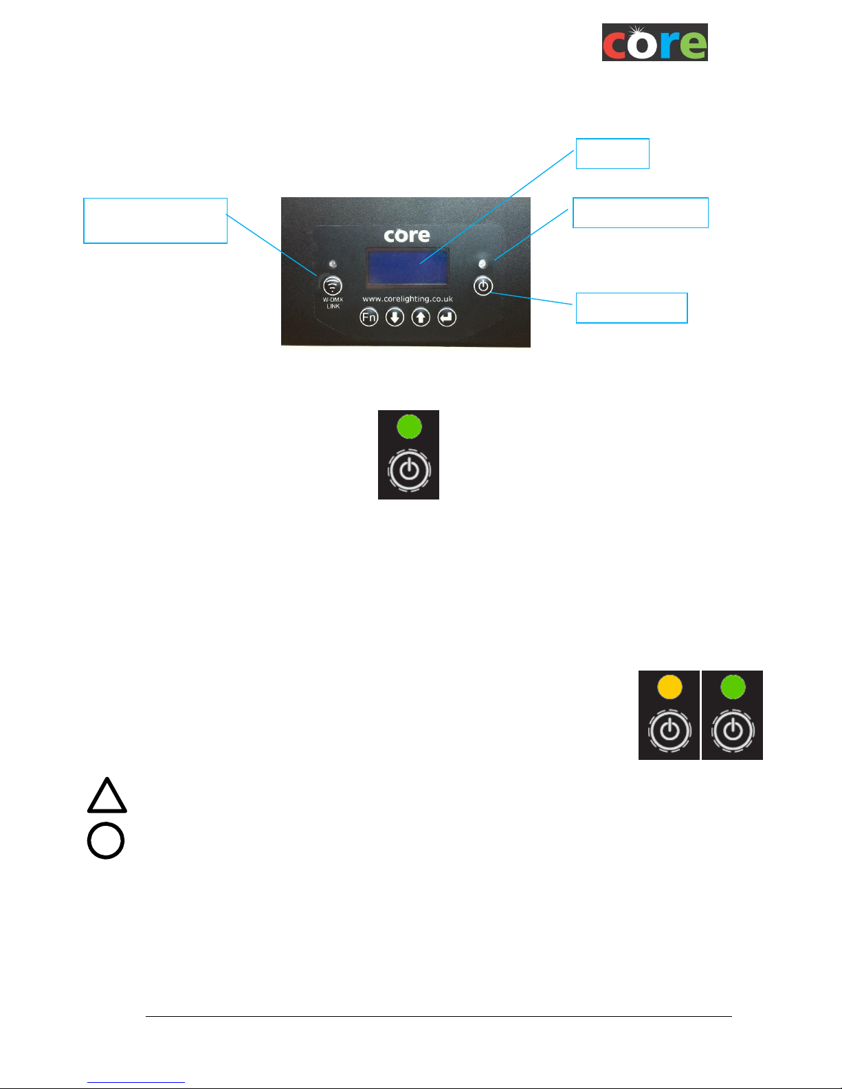
StripPoint Key Elements
Operation
Turning On and Off
Push and hold this power button for >1 second to switch the unit ON or OFF
The display will show “CORE Lighting” and software version for a few seconds before starting
The display backlight will extinguish after a short time to reduce power use
Battery Charging
The fixture has a built-in charger optimized for the battery and will charge while attached to the
mains supply whether the unit is active or not
Only use the supplied mains cable or charging case
For best results recharge battery fully before storage
When charging in the charging case, it is best to ensure the case lid remains
open to disperse heat, although the lid may be closed in cooler climates.
Switch off the charger unit and unplug once fully charged
Whilst charging the LED indicator will illuminate in RED or AMBER
(Red indicates an empty battery moving to Amber when significantly charged)
Once fully charged the LED indicator will show GREEN
!
DO NOT use any charger other than the unit supplied with the StripPoint.
When using a charging flight case, ensure the unit is pushed fully down on the charging
connector. The charge light on side of the unit should illuminate to signify this has been
done.
Charged
Charging
Power On/Off
Charging Status LED
Display
WDMX button and
LED indicator
Page 9
StripPoint User Manual rev.1_0
7
Mains Power
The fixture can be run from mains power attached to the “PowerCON” connector (PowerCON True1)
on the side
Whilst running from mains the mains symbol is shown in the top right hand corner of the display.
It will recharge the battery when mains is applied to the Powercon input connector but note that the
rate of charging is reduced if the fixture is on
A Powercon mains output connector on the LHS of the fixure allows mains to be daisy-chained from
one fixture to another.
! Note that no more than 4 units can be daisy chained.
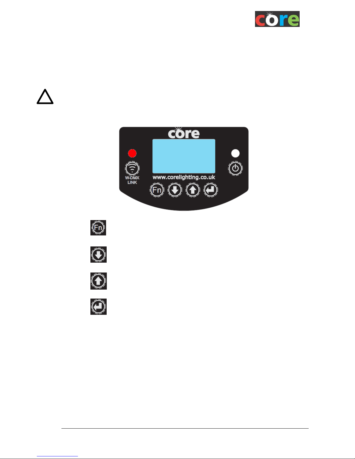
Control Panel
Enables changes to FUNCTION or SETTINGS menus
Exits from the current option or menu
Navigates backwards through the menu list
or decrements a numeric value
or navigates back through available values
Navigates forward through the menu list
or increments a numeric value
or navigates forward through available values
Enters the currently displayed menu option
or saves the currently displayed value
FUNCTION
static
Page 10
StripPoint User Manual rev.1_0
8
Function Modes
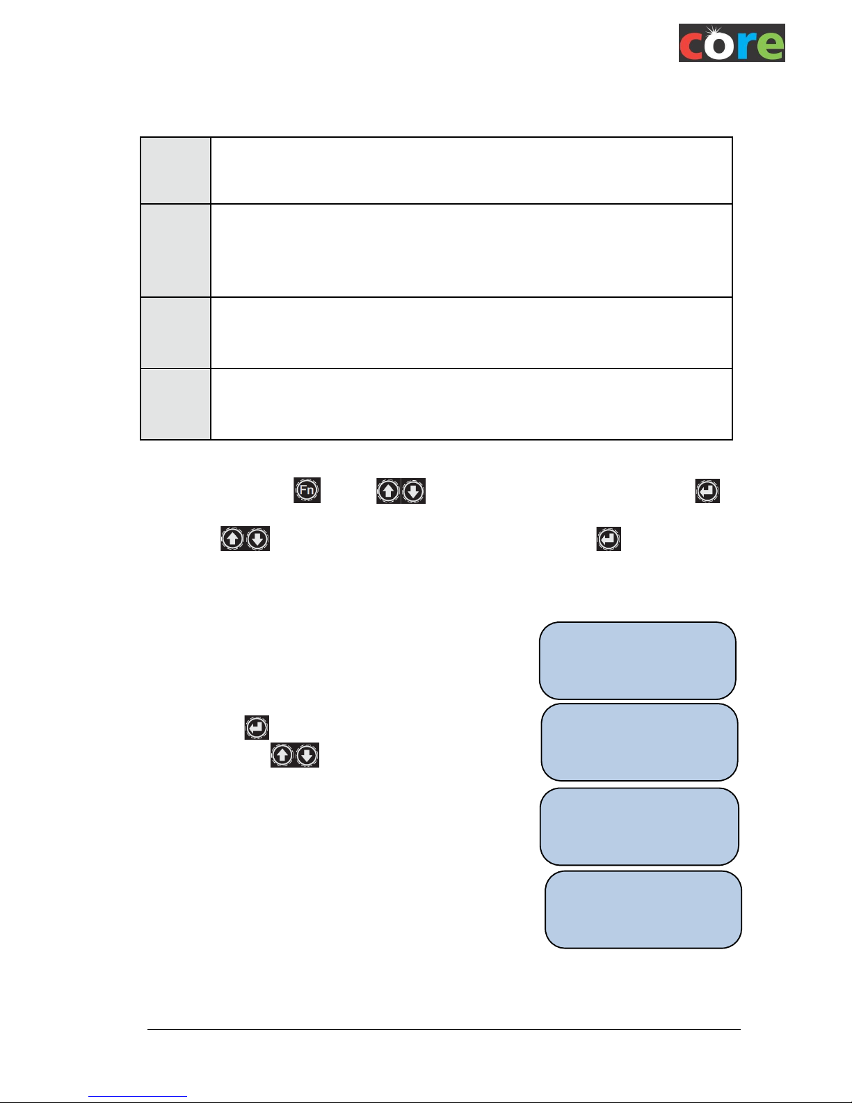
There are three modes of Operation, accessed through the FUNCTION menu;
To change Function press . Use the keys to select “CHANGE Function” and press
to accept.
Then use the keys to select the required function as above and press .
The three modes of operation are discussed in more detail below.
Function CUSTOM
When in Custom Colour mode the display indicates the
current selected colour.
Simply press to step through the colours or accept a
colour value. Use keys to change the value.
Value range 0 to 255.
Tip: Mix red & blue for purple/pink
Tip: Mix red & green for orange/yellow
Tip: Mix red & green with White for warm shades of white
Function
CUSTOM
This mode allows the fixture to output a static Red, Green, Blue or White colour, or any
combination thereof; each colour may be set to any value 0 to 255.
Any W-DMX input signal, if present, is ignored but in Master mode the setting is
transmitted
Function
STATIC
In this mode the fixture outputs a static LEE or preset ‘cc’ colour as selected.
The selection is remembered if the unit is switched off then back on or put into another
mode.
Any W-DMX input signal, if present, is ignored. but in Master mode the setting is
transmitted
Function
EFFECT
In this mode the fixture outputs patterns and sequences which is described in more detail
below.
Any W-DMX input signal, if present, is ignored but in Master mode the setting is
transmitted.
Function
DMX
In this mode the fixture is under control of Wireless DMX (W-DMX) so may be controlled
by a W-DMX compatible device or via the DMX input connector
Mster/Slave and the DMX address are selected within the DMX function mode.Full
details are provided below
CUSTOM
Colour
Set Col.
Red: 255
Set Col.
Green: 000
Set Col.
Blu: 128
Page 11

StripPoint User Manual rev.1_0
9
Function STATIC
When in STATIC mode the display indicates the current
selected colour.
To change the current selected colour press .
The last character of the currently selected colour is underlined
Use the keys to select a colour from the built-in library of 70
pre-programmed colours, including 60 popular LEE Filter Colours
STATIC
Lee345
The colour changes when cycling through the available options. The selected colour is only saved
when <ENTER> is pressed. If <ENTER> is not pressed, the colour reverts to the previously
selected colour after 8 seconds.
Available Colours
cc001
White
Lee075
Evening Blue
Lee157
Pink
cc002
Half Flesh Tone
Lee089
Moss Green
Lee159
No Colour Straw
cc003
Full Flesh Tone
Lee100
Spring Yellow
Lee162
Bastard Amber
cc004
Half Mint Green
Lee101
Yellow
Lee170
Deep Lavender
cc005
Mint Green
Lee102
Light Amber
Lee174
Dark Steel Blue
cc006
Half Ice Blue
Lee103
Straw
Lee181
Congo Blue
cc007
Full Ice Blue
Lee104
Deep Amber
Lee192
Flesh Pink
cc008
Soft Red
Lee106
Primary Red
Lee199
Regal Blue
cc009
Soft Green
Lee107
Light Rose
Lee323
Jade
cc010
Soft Blue
Lee108
English Rose
Lee341
Plum
Lee113
Magenta
Lee345
Fuchsia
Lee002
Rose Pink
Lee115
Peacock Blue
Lee353
Lighter Blue
Lee009
Pale Amber Gold
Lee117
Steel Blue
Lee652
Urban Sodium
Lee010
Medium Yellow
Lee118
Light Blue
Lee722
Bray Blue
Lee013
Straw Tint
Lee119
Dark Blue
Lee724
Ocean Blue
Lee015
Deep Straw
Lee121
Lee Green
Lee738
Jazz Green
Lee017
Surprise Peach
Lee126
Mauve
Lee765
Lee Yellow
Lee019
Fire
Lee127
Smoky Pink
Lee776
Nectarine
Lee020
Medium Amber
Lee135
Deep Amber Gold
Lee777
Rust
Lee024
Scarlet
Lee136
Pale Lavender
Lee779
Bastard Pink
Lee026
Bright Red
Lee138
Pale Green
Lee789
Blood Red
Lee046
Dark Magenta
Lee139
Primary Green
Lee793
Vanity Fair
Lee058
Lavender
Lee147
Apricot
Lee795
Magical Magenta
Lee068
Sky Blue
Lee153
Pale Salmon
Page 12
StripPoint User Manual rev.1_0
10
Set DMX
Addr: 001
DMX +
Master
DMX Type
Master
Function DMX
CORE StripPoint is equipped with a Wireless Solution W-DMX
wireless radio transmitter and receiver. This allows the fixture colour
to be set up by or synchronized with sequences produced by a DMX
lighting controller or other StripPoint unit when in Receive, or SLAVE
mode.
Alternatively when in MASTER mode the unit can be linked to many Slave units which will then
duplicate the output from the Master on the Slave units.
(NB only 4 channel mode is output at the time of going to press).
If not using a StripPoint as a Master unit then a compatible W-DMX transmitter attached to a DMX
controller is necessary, available separately. This could be a lighting desk, a specific controller, or a
CORE ColourPoint, Point 15, 20 or 30 Master unit.
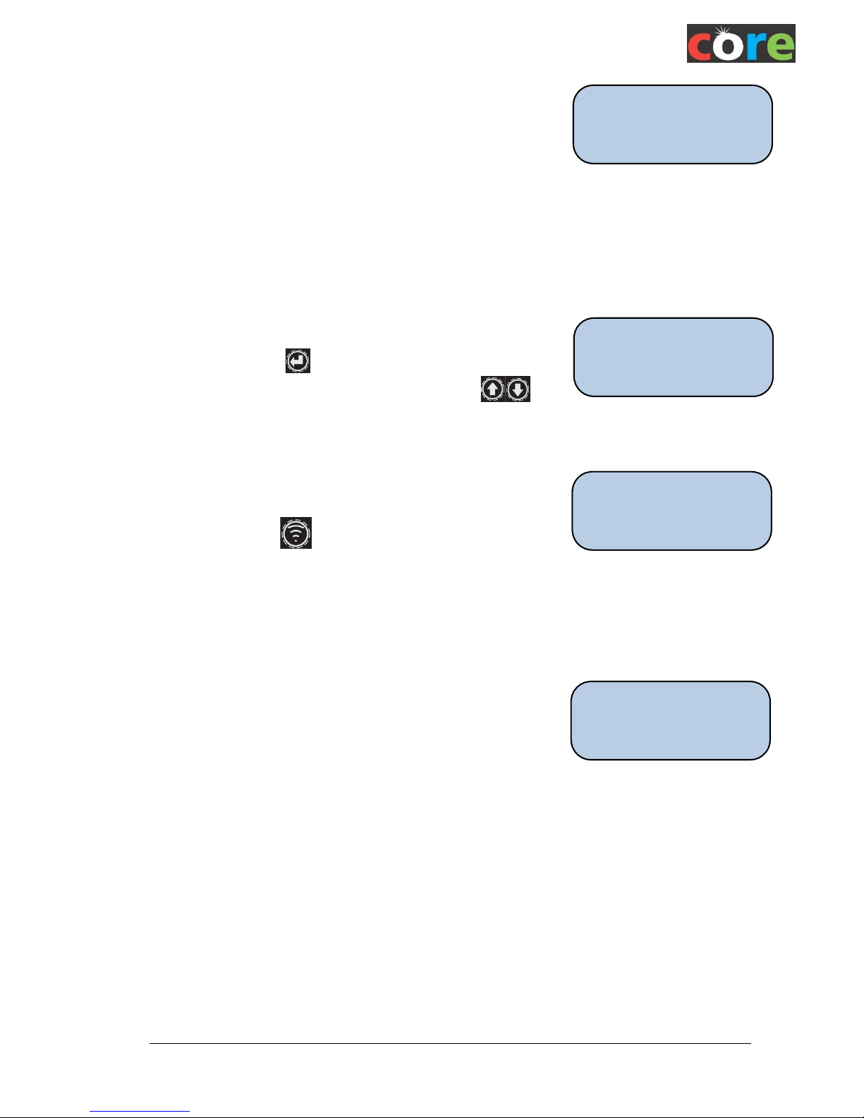
When the ‘Function DMX’ screen is shown, after a few seconds the
screen automatically reverts to the last mode used, either Master or
Slave. By pressing the key the ‘DMX Type’ screen is shown,
which allows the user to select the opposite mode using key.
DMX Master Operation
Once Master mode is set change the function to CUSTOM, EFFECT
or STATIC and any Slave units will follow the Master.
The Master may be linked to any number of unlinked slaves by
pressing the Wireless key momentarily.
The adjacent link light will flash for a few seconds whilst it links to the
unlinked slave units then go solid.
While in Master Mode the StripPoint will also output DMX data on the 5-pin DMX Output connector
DMX Slave Operation
When in DMX Slave mode the display will show the current active
DMX Start Address so the unit can be controlled from elsewhere.
The fixture can follow data received wirelessly or via the DMX cable
input. If the cable input is used please ensure that the wireless card is
disabled in the SETTINGS menu.
For Wireless DMX connection (Wireless Solutions W-DMX) the Slave unit needs to be paired with the
StripPoint Master unit or W-DMX transmitter which it will receive signals from (see below for W-DMX
Pairing).
The number of channels being controlled and the pixel mapping depends on the “DMX MODE” which
is set in settings Menu. (All RGBW pixels will follow the same colour whilst in 4/5 channel mode,
whilst in 72 channel mode each of the 18 pixels are independently addressable with 4 colours red,
green, blue and white).
In SLAVE mode the entire universe is output on the 5-pin output connector either when used wirelessly
or from a cable, which allows this fixture to be daisy-chained to the next fixture cable DMX Input and so
on.
Function
DMX
Page 13
StripPoint User Manual rev.1_0
11
DMX Addressing
In Slave mode DMX channel mapping for each Pixel and LED on the fixture can be selected. A pixel
consists of 4 leds, Red, Green. Blue, White. Pixel 1 is the right-hand end LED on the batten, pixel 18 is
the left-hand end LED (with the LCD screen facing towards the user)
DMX Start Address:
To set the DMX start address press key when the display shows the current address. Use the
keys to select the new start address then to confirm.
In Master mode the StripPoint will transit in 4 channel mode only (at the time of going to press).
Function EFFECT
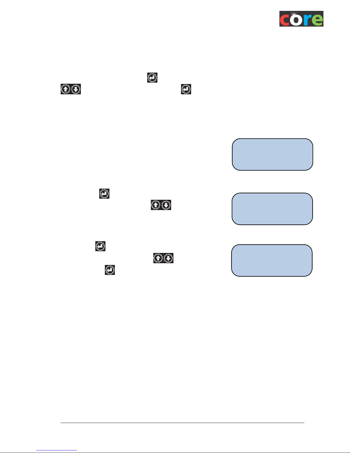
The StripPoint is equipped to generate a number of special effects as
a stand-alone unit when Function EFFECT is selected. This is true
whether DMX is placed in Slave or Master Mode, although at the time
of going to press will not output these to connected Slave units when
DMX is in Master Mode (this feature may be added as a future development).
By pressing the key the last used effect type is brought up,
which can then be changed using the keys.
By pressing the key to confirm the effect type, the speed can be
adjusted from a range 1 to 10 using the keys. When
confirmed with the key the screen reverts to show the effect and
speed.
Function
EFFECT
EFFECT
R’bow 10
Type:
R’bow 1
Page 14
StripPoint User Manual rev.1_0
12
W-DMX Pairing and Unpairing
StripPoint units need to be manually paired with the lighting control unit equipped with a W-DMX
transmitter. This could be a lighting desk with DMX Output, or another CORE Master unit with a W-DMX
transmitter inside.
This allows a group of StripPoint fixtures to be controlled from a lighting desk or Master using the
built-in colour cycles (inside StripPoint/ColourPoint/Point15/20/30). Or set up individually selected
colours across many units at once from just one Master unit.
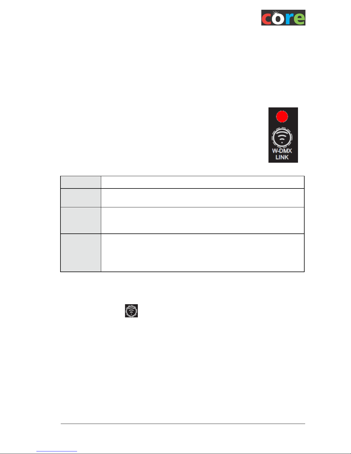
W-DMX Link LED
The W-DMX link status is shown by the LINK LED, this provides information on the
W-DMX link. This follows the same status indication as all Wireless Solution W-DMX
products.
When in MASTER mode this LED should be steadily ON except while pairing.
Description for operation in Slave mode:
OFF
If the LED is OFF the StripPoint is not paired with a W-DMX transmitter
FLASHING
If the LED is FLASHING the StripPoint is paired with a W-DMX
transmitter, but the transmitter is switched off.
STEADY ON
If the LED is STEADILY ILLUMINATED the StripPoint is paired with, and ready to
receive data from a W-DMX transmitter. This is a fully paired and fully
functioning system.
UNEVEN
FLASHING
If the LED is FLASHING unevenly, the StripPoint could be paired with a
W-DMX transmitter, the transmitter is switched on, but there is no
DMX Input to the transmitter.
Alternatively, it could mean a fault condition on the W-DMX card inside
the StripPoint.
Unpairing a Slave fixture from W-DMX Transmitter units
Switch on the StripPoint
Press and hold the button until the W-DMX LINK LED is turned OFF.
StripPoint is now unpaired from the W-DMX transmitter.
Page 15
StripPoint User Manual rev.1_0
13
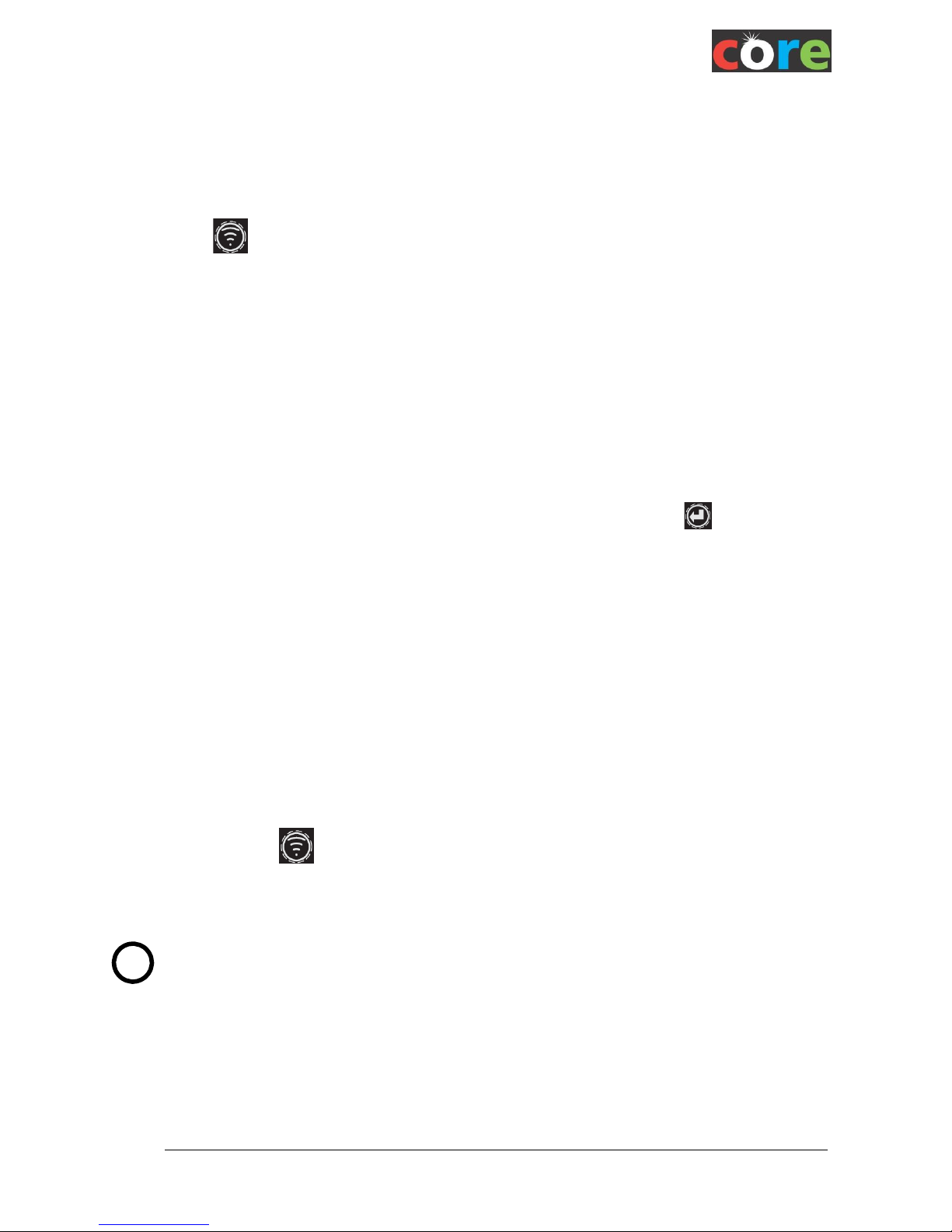
Pairing a StripPoint slave to a W-DMX Transmitter unit or CORE Master unit
Switch on the StripPoint Slave and ensure it is in DMX Slave Mode (see above DMX Slave
Operation).
Ensure the StripPoint is unpaired from any other transmitter (i.e. the LINK LED is OFF) – above
Unpairing a Slave fixture from W-DMX Transmitter Units.
Ensure the transmitter is within range and switched on.
On most W-DMX transmitters (including CORE ColourPoint and StripPoint units) press the
button on the master for about 1s.
The transmitter will scan for all unlinked receivers for around 10 seconds; the LED will flash on
the Slave and Master units during the process of pairing.
If pairing is successful the LINK LED on the Slave StripPoint will illuminate permanently.
ALL Unlinked StripPoint units (and other Unlinked W-DMX units too) may be linked at the same
time. No apparent limit to the number being paired.
For receiver units not to be paired with this transmitter, simply switch off those unwanted
receivers before this pairing process. They may be paired with a different transmitter after
switching on again and repeating the pairing process with the new transmitter.
Pairing with a CORE Point15, Point20 or Point30 Master unit
Switch on the StripPoint.
Ensure the StripPoint is unpaired from any other transmitter (the LINK LED is OFF) – above.
Ensure the Master unit is within range and switched on.
Select MODE MSTR MSTR DMX Add Unit ‘+’ to select ‘YES’ to confirm.
The transmitter will scan for all unlinked receivers for around 10 seconds; the LINK LEDs flash.
If pairing is successful the LINK LED on the StripPoint will illuminate.
For successful linking the receiver must fulfill the following conditions:
Distance to transmitter (in free air)
Less than 200m for Micro model transmitter
Less than 500m for BlackBox or WhiteBox transmitter
Position above obstacles (e.g. crowds and tress)
Minimum 1m
Pairing a StripPoint Master to other fixtures
Ensure the fixtures to be controlled are in SLAVE mode and unlinked (the LINK LED is OFF –
above.)
Ensure the Master unit is within range and switched on.
Press the button for about 1s and the W-DMX led will flash indicating that it is scanning for
Slave fixtures. On completion the led will stay on solidly and will glow permantly on the linked
Slave fixtures too.
i Pairing to a transmitter is remembered after power off or the battery is depleted.
This allows the system pairing to be set up in a warehouse and the whole system simply switched on at
the site, which makes deployment very simple.
Page 16
StripPoint User Manual rev.1_0
14
Additional Settings
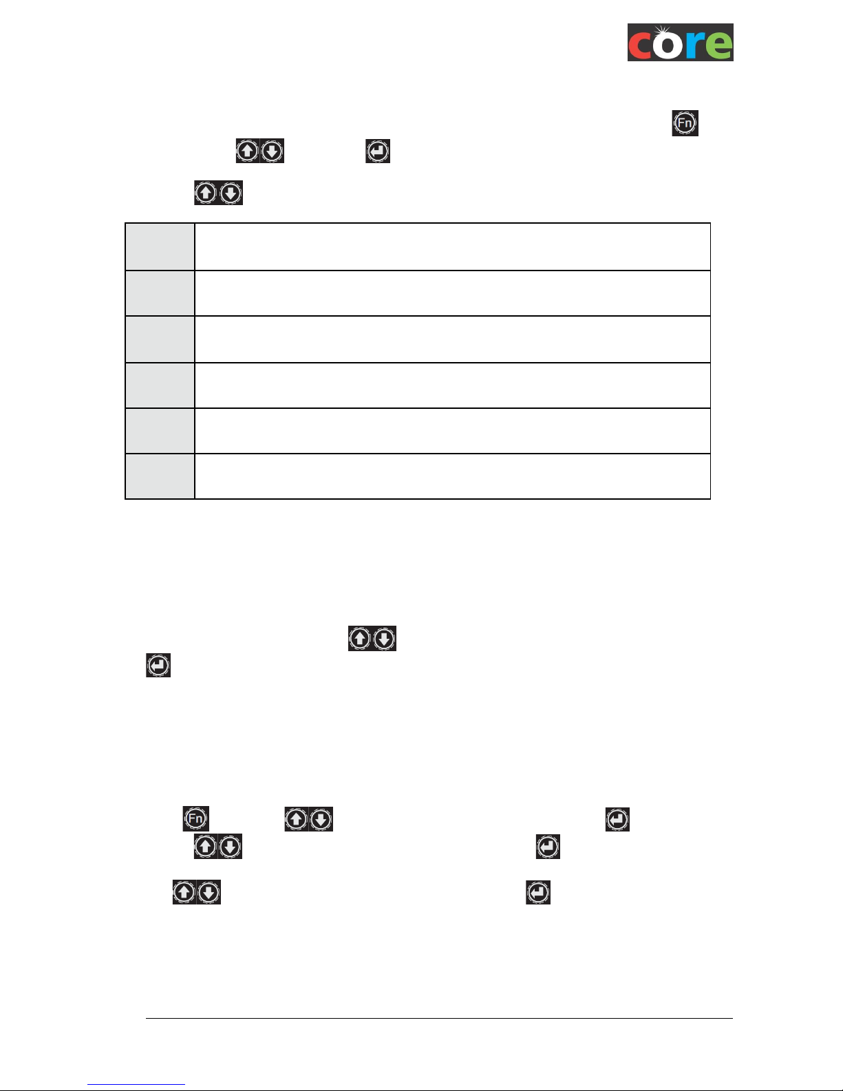
A number of parameters can be set up in the SETTINGS menu, this is selected by pressing
followed by the keys and the key to select to select “CHANGE Settings”.
Use the keys to scroll between:
Power
Mode
Normal or Longlife operation to give longer battery life
BRIGHTNS
Control
Adjusts the light output in stand-alone mode
DMX
Mode
Selects the DMX mapping mode between 4, 5, 8, 9 and 72 channels. Details of the
mapping are shown below.
PWM
Freq
Adjusts the PWM frequency of the LED drive to optimize operation with TV cameras
Lamp
Profile
Fade profile selection between Sq. law or Linear
WDMX
Power
Enables the power to the wireless module so it can be disabled for Wired DMX
applications
Power Mode
The “Normal” option provides maximum light output.
“LongLife” reduces the LED output by 50%, therefore enables 2 x running period for ALL
FUNCTIONS, whether stand-alone, DMX Master or DMX Slave (even when controlled from
another Master).
Having selected Power Mode, Use keys to toggle between “Norm” and “LongLife” then press
to save changes. This setting affects all modes so that the battery life each unit can be individually
set, irrespective of what’s controlling it.
Brightness Control
A separate brightness control that can control the output of the unit in stand-alone mode:
The value may be changed from 0 to 100%
Press and use the keys to select “CHANGE Settings” then press . to accept.
Use the keys to select “BRIGHTNS CONTROL” and press to select.
Use keys to toggle between “0%” and “100%” then press to save changes. This setting
adjusts Static, Cust Col and Effect modes only.
In DMX slave mode the Brightness control will have no effect if the DMX mode includes dimmer data. Ie
the Brightness control will be inactive when set to 5 channel and 9 channel mode but active when 4
channel, 8 channel and 72 channel is selected.
Page 17
StripPoint User Manual rev.1_0
15
i
DMX Mode
The DMX channel mapping for each LED output on the fixture can be selected. A pixel consists of 4
LEDs: Red, Green. Blue, White. Pixel 1 is the right-hand end LED cluster on the batten, pixel 18 is the
left-hand end LED cluster.
DMX form
4 chan
All 18 pixels are controlled by 4 DMX channels for Red, Green Blue, White.
No dimmer channel
5 chan
All 18 pixels are controlled by 4 DMX channels for Red, Green Blue, White and the 5th
channel controls the brightness (Dimmer channel)
8 chan
Pixels 1 to 8 on RHS of fixture are controlled by channels 1 to 4
Pixels 9 to 18 on LHS of fixture are controlled by channels 5 to 8. No dimmer channel
9 chan
Pixels 1 to 8 on RHS of fixture are controlled by channels 1 to 4
Pixels 9 to 18 on LHS of fixture are controlled by channels 5 to 8
Channel 9 controls the overall brightness (Dimmer channel)
72 chan
Full pixel mapping such that each led in each pixel is controlled. No dimmer channel
A full mapping table is shown in Appendix 1 of this document.
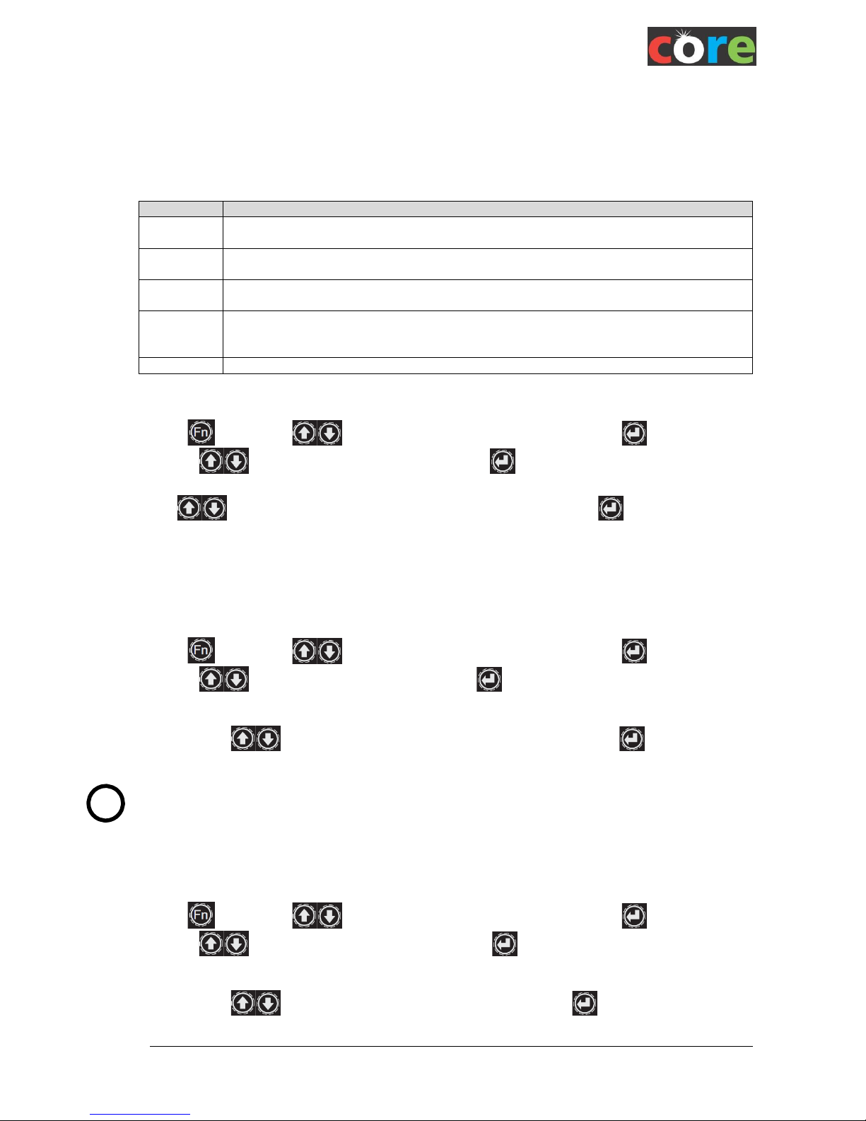
Press and use the keys to select “CHANGE Settings” then press . to accept.
Use the keys to select “DMX Format” and press to select.
Use keys to toggle between 4, 5, 8, 9 or 72 Chan mode then press to save changes.
PWM Frequency Control
For HD TV work StripPoint is equipped with an option to adjust the PWM frequency of the LEDs to
prevent ‘beating’ with the TV scan frequency.
Press and use the keys to select “CHANGE Settings” then press . to accept.
Use the keys to select “PWM Freq” and press to select.
Then use the keys to select a from value from 244Hz to 1.9kHz. Press to save
changes and the screen will revert to showing the ‘Function’ mode.
Beware that when using the higher frequencies the resolution of the colour intensity steps
is reduced, so the effect of colour changing can become less smooth and more ‘steppy’.
Lamp Profile
The dimming curve can be selected to optimize for different applications
Press and use the keys to select “CHANGE Settings” then press . to accept.
Use the keys to select “Lamp Profile” and press to select.
Then use the keys to select “Sq. Law” or “Linear” curve. Press to save changes and
the screen will revert to showing the ‘Function’ mode.
Page 18
StripPoint User Manual rev.1_0
16
W-DMX Power
The Wireless DMX can be turned off so the unit will only respond to, and transmit from, the physical
DMX connectors
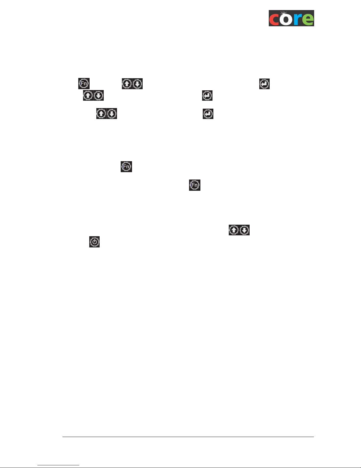
Press and use the keys to select “CHANGE Settings” then press . to accept.
Use the keys to select “DMX Power” and press to select.
Then use the keys to select “On” or “Off”. Press to save changes and the screen will
revert to showing the ‘Function’ mode.
Keypad Lock
The keypad may be locked to prevent tampering or inadvertent adjustment of the unit.
To Lock: Hold down the whilst switching ON the unit to Lock.
To Unlock: First switch OFF the unit. Hold down the whilst switching ON the unit to Unlock.
Master Reset
All settings can be reset to the default factory set up by pressing the keys while turning the unit
on with the button.
Page 19

StripPoint User Manual rev.1_0
17
Mechanical
Dimensions
Length : 1000mm
Height: 157mm (with feet attached)
Width: 74mm
Weight: 6.0Kg
Floor mounting: the unit can be pivoted through 90 degrees providing vertical and horizontal beams
Truss mounting options: The unit is supplied with Adjustable feet designed to be attached to
standard 10mm mountings. Alternatively the StripPoint can be attached to a baseplate using quickrelease, ¼ turn fixings available from CORE Lighting Ltd. This baseplate has 10mm fixings to be
attached to trussing walls or other structures.
Safety Fixings: the StripPint has 10mm eyes in the back of the chassis and M10 blind mountings
allowing a range of safely clips to be attached.
Antenna
The antenna is a high-gain type similar in performance to the Wireless Solutions W-DMX 2dB
standard antenna according to testing. This antenna is now fitted to all CORE POINT units.
Page 20

StripPoint User Manual rev.1_0
18
Warranty
CORE Lighting Limited (CORE Lighting) warrants this product to be free from defects in materials and
workmanship (subject to the terms set forth below).
CORE Lighting will repair or replace (at CORE Lighting's option) this product or any defective parts in this
product. The standard warranty period is 24 months from date of purchase, excluding battery pack which is 12
months, although this period may vary from country to country. If in doubt consult your dealer and ensure that
you retain proof of purchase.
To obtain warranty service, please contact the CORE Lighting authorised dealer from which you purchased this
product. If your dealer is not equipped to perform the repair of your CORE Lighting product, it can be returned
directly to CORE Lighting, with carriage being paid at your own expense. You will need to ship this product in
either its original packaging or packaging affording an equal degree of protection. Providing the product is
found to be faulty, CORE Lighting will pay for return carriage.
Proof of purchase in the form of a bill of sale or receipted invoice, which is evidence that this product is within
the warranty period, must be presented to obtain warranty service.
This Warranty is invalid if (a) the factory-applied serial number has been altered or removed from this product
or (b) this product was not purchased from a CORE Lighting authorised dealer.
This Warranty does not cover cosmetic damage or damage due to acts of God, accident, misuse, abuse,
negligence, commercial use, or modification of, or to any part of, the product. This Warranty does not cover
damage due to improper operation, maintenance or installation, or attempted repair by anyone other than
CORE Lighting or a CORE Lighting dealer, or authorised service agent which is authorised to do CORE Lighting
warranty work. Any unauthorised repairs will void this Warranty. This Warranty does not cover products sold
AS IS or WITH ALL FAULTS.
REPAIRS OR REPLACEMENTS AS PROVIDED UNDER THIS WARRANTY ARE THE EXCLUSIVE REMEDY OF THE
CONSUMER. CORE LIGHTING SHALL NOT BE LIABLE FOR ANY INCIDENTAL OR CONSEQUENTIAL DAMAGES FOR
BREACH OF ANY EXPRESS OR IMPLIED WARRANTY IN THIS PRODUCT. EXCEPT TO THE EXTENT PROHIBITED BY
LAW, THIS WARRANTY IS EXCLUSIVE AND IN LIEU OF ALL OTHER EXPRESS AND IMPLIED WARRANTIES
WHATSOEVER INCLUDING, BUT NOT LIMITED TO, THE WARRANTY OF MERCHANTABILITY AND FITNESS FOR A
PRACTICAL PURPOSE.
Some countries and US states do not allow the exclusion or limitation of incidental or consequential damages
or implied warranties so the above exclusions may not apply to you. This Warranty gives you specific legal
rights, and you may have other statutory rights, which vary from state to state or country to country.
For any service, in or out of warranty, please contact your dealer.
Page 21

StripPoint User Manual rev.1_0
19
Compliance Information
System Compliance
CORE Lighting Limited declares that this product conforms to the specifications listed in this manual, following
the provisions of the European R&TTE directive 1999/5/EC:
Restrictions on Hazardous Substances (RoHS) (2002/95/CE)
Electromagnetic Compatibility (2004/108/EC).
Safety (EN 60950)
Technical requirements for radio equipment. (EN 300 328)
CAUTION—This equipment is intended to be used in all EU and EFTA countries.
Outdoor use may be restricted to certain frequencies and/or may require a license for operation. Contact local
Authority for procedure to follow.
FCC & Industry Canada Statement for Radio Compliance
W-DMX Transmitter & Receiver
We,
CORE Lighting Limited
Prindion House
Kingsmill Lane
Painswick
Gloucestershire GL6 6SA
declare under our sole responsibility that the product
FCC ID: UQT-WDMXOEMPCBF
Model: W-DMX OEM PCB F
complies with Part 15 of the FCC Rules.
Operation is subject to the following two conditions:
(1) this device may not cause harmful interference, and
(2) this device must accept any interference received, including interference that may cause undesired
operation.
To assure continued compliance, any changes or modifications not expressly approved by the party responsible
for compliance could void the user's authority to operate this equipment.
NOTE: This equipment has been tested and found to comply with the limits for a Class B digital device,
pursuant to Part 15 of the FCC Rules. These limits are designed to provide reasonable protection against
harmful interference in a residential installation.
This equipment generates, uses, and can radiate radio frequency energy and, if not installed and used in
accordance with the instructions, may cause harmful interference to radio communications.
However, there is no guarantee that interference will not occur in a particular installation. If this equipment
does cause harmful interference to radio or television reception, which can be determined by turning the
equipment off and on, the user is encouraged to try and correct the interference by one or more of the
following measures:
• Reorient or locate the receiving antenna.
Page 22

StripPoint User Manual rev.1_0
20
• Increase the separation between the equipment and receiver.
• Connect the equipment into an outlet on a circuit different from that to which the receiver is connected.
• Consult the dealer or an experienced radio/TV technician for help.
RF Exposure Warning for North America, and Australia
Warning! To meet FCC and other national safety guidelines for RF exposure, the antennas for this device must
be installed to ensure a minimum separation distance of 20cm (7.9 in.) from persons.
WEEE & RoHS Statement
The European Directive 2002/96/EC on Waste Electrical and Electronic Equipment (WEEE), requires that
products must not be disposed of the normal unsorted municipal waste stream. Appliances must be collected
separately in order to optimise the recovery and recycling of the materials they contain and reduce the impact
on human health and the environment.
The consumer must contact their local authority or retailer for information concerning disposal of their
products.
CORE Lighting provides a take-back facility for batteries used within CORE Lighting products, although the
expense for transport remains the liability of the consumer. Please contact CORE Lighting directly if this service
is required.
Page 23

StripPoint User Manual rev.1_0
21
Appendix 1 – DMX Mapping Table
DMX
CHANNEL
Rx DMX MODE (selected in SETTINGS menu)
4 channel
5 channel
8 channel
9 channel
72 channel
1
RED on all
pixels
RED on all
pixels
RED on pixels
1-9
RED on pixels
1-9
R on Pixel 1
2
GREEN on all
pixels
GREEN on all
pixels
GREEN on
pixels 1-9
GREEN on
pixels 1-9
G on Pixel 1
3
BLUE on all
pixels
BLUE on all
pixels
BLUE on pixels
1-9
BLUE on pixels
1-9
B on Pixel 1
4
WHITE on all
pixels
WHITE on all
pixels
WHITE on
pixels 1-9
WHITE on
pixels 1-9
W on Pixel 1
5 DIMMER on all
pixels
RED on pixels
10 - 18
RED on pixels
10 - 18
R on Pixel 2
6
GREEN on
pixels 10 -18
GREEN on
pixels 10 -18
G on Pixel 2
7
BLUE on pixels
10-18
BLUE on pixels
10-18
B on Pixel 2
8
WHITE on
pixels 10-18
WHITE on
pixels 10-18
W on Pixel 2
9
DIMMER on all
pixels
R on Pixel 3
10
G on Pixel 3
11
B on Pixel 3
12
W on Pixel 3
13
R on Pixel 4
14
G on Pixel 4
15
B on Pixel 4
16
W on Pixel 4
.
. . . . . . . . .
61
R on Pixel 16
62
G on Pixel 16
63
B on Pixel 16
64
W on Pixel 16
65
R on Pixel 17
66
G on Pixel 17
67
B on Pixel 17
68
W on Pixel 17
69
R on Pixel 18
70
G on Pixel 18
71
B on Pixel 18
72
W on Pixel 18
 Loading...