

Page 1

Trademarks
Corega
TM
is a trademark of Corega Holdings KK., Japan.
Other trademarks, brand and product names are acknowledged as
trademarks of their respective holders. Information is subject to
change without notice.
All rights reserved.
617-00041-01
Page 2
BAR-WL
BROADBAND
WIRELESS ROUTER
GET CONNECTED
HUBS • SWITCHES • ADAPTERS • WIRELESS LAN • USB • KVMs • MEDIA CONVERTERS • ROUTERS
ENGLISH: Pg 1-28
DEUTSCH: Pg 29-56
ITALIANO: Pg 57-84
ESPAÑOL: Pg 85-112
FRANÇAIS: Pg 113-140
русский: Pg 141-168
Page 3

ENGLISH
1
Table of Contents
Technical Specifications 2
FCC Interference Statement 3
CE Declaration of Conformity 3
Features of the BAR-WL Wireless Router 3
1. Installing the BAR-WL Wireless Router 3
1.1 Package Contents 3
1.2 Front Panel LEDs 5
1.3 Rear Panel & Connections 5
1.4 Before connecting your BAR-WL Wireless Router 6
1.5 Computer System Requirements and Setup 7
1.6 Installing the BAR-WL Wireless Router 7
2. Internet Access 7
2.1 Prepare your network information 7
2.2 Web-based User Interface 8
2.3 Initial Configuration - Setup 9
2.3.1 OnePage Setup with DHCP WAN 9
2.3.2 OnePage Setup with Static IP on the WAN 11
2.3.3 OnePage Setup with PPPoE on the WAN 12
2.4 Device Administration Settings 13
2.5 Wireless 14
2.6 DHCP Configuration 15
2.7 Static Routing 16
2.8 DDNS 17
2.9 Virtual Server 18
2.10 Special Applications 19
2.11 DMZ 20
2.12 Access Control 21
2.12.1 IP Address 21
2.12.2 URL Access Setting 22
2.12.3 MAC Address Filter 23
2.13 Status Monitor 23
Appendix A.1: Installing TCP/IP 24
Appendix A.2: Fixed (Static) IP Addresses Configuration 27
Page 4

ENGLISH
2
Dimensions
175mm (L) x 117mm (W) x 32mm (H)
Weight
378g
Interface Ports
1 x RJ45 10BaseT/100BaseTX WAN port (Auto MDI/MDIX)
4 x RJ45 10BaseT/100BaseTX LAN ports (Auto MDI/MDIX)
Standards Compliance
IEEE 802.3 10BASE-T
IEEE 802.3u 100BASE-TX
IEEE 802.11b Wireless
IEEE 802.3x Flow control
Antenna
External
Frequency Range
2.4-2.497GHz
DSSS- Direct Sequence Spread Spectrum
Channels
11 Channels (US, Canada)
13 Channels (Europe)
14 Channels (Japan)
Data Transmission Rate
11Mbps / 5.5Mbps / 2Mbps / 1Mbps Auto Fall-back
Access Mode
Infrastructure mode
Data Security
Provides both 64-bit and 128-bit WEP Encryption
Output Power
18dBm (average)
Receiving Sensitivity
84dBm@11M
Coverage Area
Indoors: Up to 50M (165 ft.) @ 11Mbps
Up to 80M (265 ft.) @ 5.5Mps or lower
Outdoors: Up to 150M (500 ft.) @ 11Mbps
Up to 300M (1000 ft.) @ 5.5Mps or lower
(Depending on environment)
Management
Web-based GUI Management
Operating Environment
Operating Temperature: 0 ~ 40°C degrees
Storage Temperature: -20 ~ 60°C degrees
Humidity: 0 ~ 90% non-condensing
External Power Adapter
5VDC @ 2.5A
Agency Approvals
FCC Class B
CE Class B
GOST
Warranty
2 Years
TECHNICAL SPECIFICATIONS
Page 5

ENGLISH
3
REGULATORY COMPLIANCE
FCC Interference Statement
This device complies with Part 15 of FCC rule. Operation is subject to the following two conditions:
• This device may not cause harmful interference.
• This device must accept any interference received, including interference that may cause undesired operation.
This Broadband Wireless Router has been tested and found to comply with the limits for a Class B digital device, pursuant to Part
15 of the FCC Rules. These limits are designed to provide reasonable protection against harmful interference in a residential
installation. This equipment generates, uses, and can radiate radio frequency energy and, if not installed and used according to
the instructions, may cause harmful interference to radio communications. However, there is no guarantee that interference will
not occur in a particular installation.If this equipment does cause harmful interference to radio or television reception, which is
found by turning the equipment off and on, the user is encouraged to try to correct the interference by one or more of the
following measures:
• Reorient or relocate the receiving antenna.
• Increase the separation between the equipment or device.
• Connect the equipment to an outlet other than the receiver’s.
• Consult a dealer or an experienced radio/TV technician for assistance.
FCC Radiation Exposure Statement
This equipment complies with FCC radiation exposure limits set forth for an uncontrolled anvironment. This equipment should be
installed and operated with minimum distance 20cm between the radiator and your body.
CE Declaration of Conformity
This equipment complies with the specifications relating to electromagnetic compatibility, EN 55022/A1 Class B, and EN 50082-1.
This meets the reasonable protection requirements set ou in the European Council Directive on the approximation of the laws of
the member states relating to Electromagnetic Compatibility Directive (89/336/EEC).
Page 6

4
ENGLISH
1. Installing the BAR-WL Wireless Router
This chapter describes un-packing, familiarization, and the hardware installation of the BAR-WL Wireless Router.
1.1 Package Contents 1 x BAR-WL Wireless Router
1 x External Power Adapter
1 x Wall Mount Kit (2 screws and 2 wall plugs)
4 x Self Adhesive Rubber Feet
1 x Vertical Desk kit
1 x Ethernet Cable
1 x Installation Guide
Features
Your BAR-WL Wireless Router provides the following features:
• Allows multiple users to access Internet at the same time using a single public IP Address.
• Allows users on Ethernet LAN and wireless LAN to transfer data to each other through wireless-to-wire bridge.
• Provides wireless access roaming, best access point selection, loading balance, network traffic filtering included in wireless
roaming function.
• Provides 64bits/128bits key WEP (Wired Equivalent Privacy) wireless data encryption to secure wireless communication.
• Fully supports 802.11 open and shared key authentication.
• Integrates four switched 10/100BASE-T/TX auto-sensing ports.
• Uses NAT to allow all of your network’s PCs to connect to the Internet using only one IP address.
• Supports PPPoE that enable users to seamlessly connect to ISPs with the user familiar “dial-up” type connection interface.
• Built-in web-based user interface for easy configuration and management.
• Supports DHCP client to receive both a dynamic IP Address and a fixed IP Address from ISP.
• Built-in DHCP server to automatically assign and manage LAN IP addresses.
• Block specific users from accessing specified web sites.
• Allows external Internet users to access information from the internal target host by setting the Virtual Server.
• Provides unrestricted two-way communication between one PC on your LAN and certain Internet services like conferencing,
video and gaming applications.
Page 7
ENGLISH
5
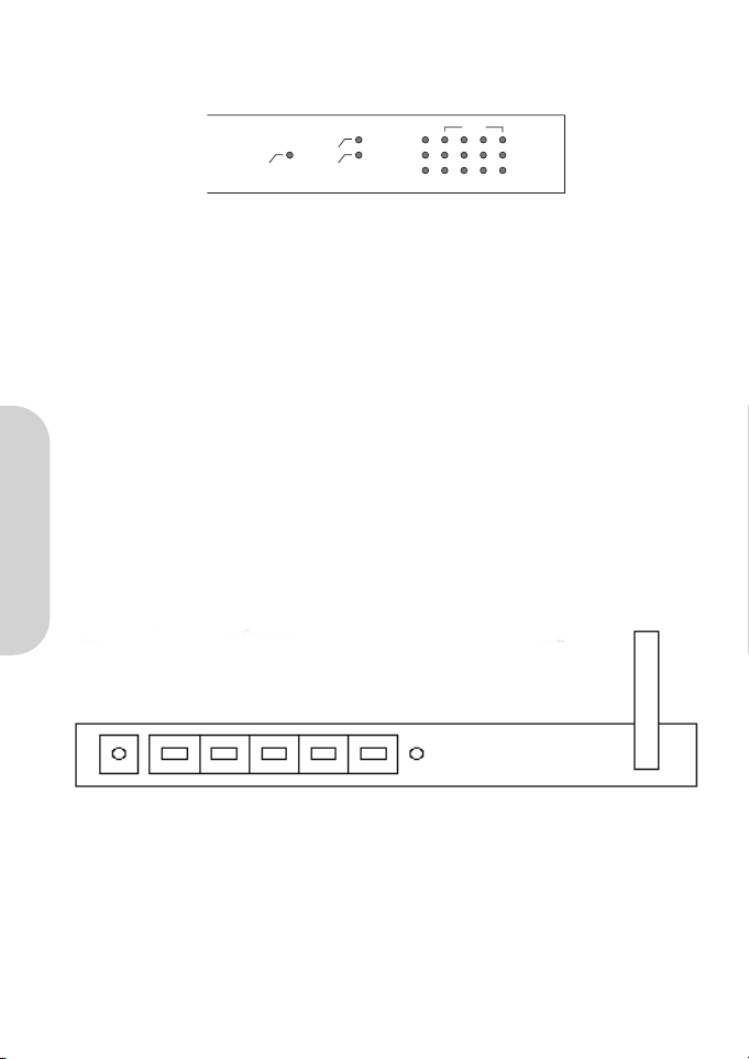
1.2 Front Panel LEDs
The following figure shows the front view of the BAR-WL Wireless Router.
• PWR (Power) Green Steady on when power is on.
• DIAG (Diagnostic) Red Light up during power on self-check. Not lit in normal operation.
• WLAN (Wireless LAN)
Enable: Green Steady on when AP (Access Point) is enabled.
Activity: Green Blinking when data is following through AP.
• WAN (WAN port)
Link: Green Steady on when ADSL/Cable Modem is properly connected.
Activity: Yellow Blinking when data is following through WAN port.
• LAN (LAN ports)
Link/Act: Green Steady on when link is up and it operates at 100Mbps.
Yellow Steady on when link is up and it operates at 10Mbps.
Green/Yellow Blinking when data is following through this LAN port.
FD/Col: Green Steady on when it operates at full duplex mode.
Off at half duplex mode.
Blinking when collision is occurred on this port.
1.3 Rear Panel & Connections
The following figure shows the rear view of the BAR-WL Wireless Router.
•Init Press the Initialization button quickly to reboot and re-initialize the device. Press the Initialization button of
longer than 3 seconds to clear any configuration and reset the router back to factory default values.
•WAN This port is for connecting to the Wide Area Network ADSL or Cable Modem.
• LAN 1-4 These ports are used to connect computers and peripherals to the BAR-WL.
• Power This socket is used to connect the external power supply to the router.
Power WAN 1 2 3 4 Init
Power
Link
Act
100M
Link/Act
Col/Fdx
1
LANWANWLAN
2 3 4
Page 8
ENGLISH
6
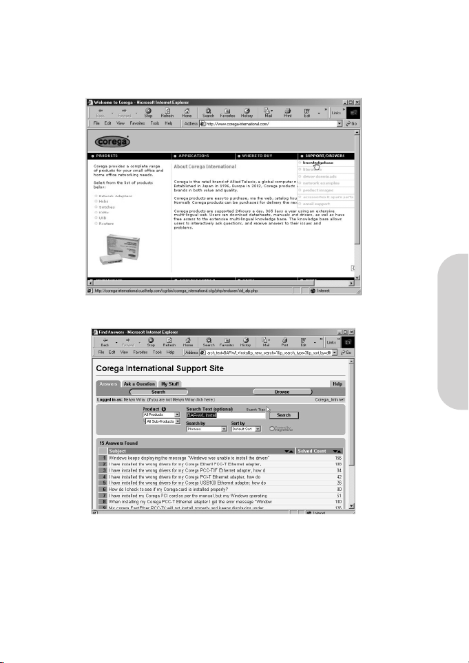
1.4 Before connecting your BAR-WL Wireless Router
Before you connect your BAR-WL Wireless Router, Corega recommend that you download installation instructions particular to
your ISP from the Corega website. These instructions will inform you how to configure the BAR-WL to work with your ISP.
www.corega-international.com
Select the knowledge base
• Enter BAR-WL in the Sub-product category, and the name of your ISP in the Search Text field.
• Press ‘Search’.
In addition, Corega recommend that you visit the URL support site of your ISP, and download and print any information they have
on your type of connection.
Some ISPs will require the user to enter the MAC address of the equipment connected to the ADSL/Cable modem. The MAC
address of the WAN port of the BAR-WL is on the base of the router. The MAC address will be of a format:
000941 2E2ACB
Page 9
ENGLISH
7
1.5 Computer System Requirements and Setup
To connect to the Internet, an external ADSL or Cable modem and an Internet access account from an ISP are required. In order to
operate with the BAR-WL Wireless Router, each PC that is to be connected should have the following things installed:
• Ethernet NIC (Network Interface Card: a 10Base-T or 10/100Base-T/TX Ethernet card), or wireless client card for wireless
connection.
• System OS: Windows 95, Windows 98, Windows NT4.0, or Windows 2000, or Windows XP.
• TCP/IP network protocol.
• Web browser, such as Microsoft Internet Explorer 4.0 or later, or Netscape Navigator 4.0 or later.
Note! If your computer does not have TCP/IP installed, please read Appendix A before continuing with the installation.
1.6 Installing the BAR-WL Wireless Router
Corega recommend that to initially configure the BAR-WL Wireless Router, that you connect a computer to the router through one
of the LAN ports. (Do not try initially installing the router using a wireless connection).
1. Disconnect the PC from a functioning broadband connection.
2. Connect the WAN port of the router to the ADSL/Cable modem using the original cable.
3. Connect the computer to the BAR-WL Wireless Router using the supplied Ethernet Cable.
4. Connect the power adapter to the BAR-WL Wireless Router.
5. In the majority of cases, the PC will require a Dynamic IP address, which will be automatically allocated by the BAR-WL router
after re-booting your PC. To access any of the setup screens of the router – point a browser at 192.168.1.1. If the router
does not respond, check the IP configuration of the PC – see Appendix A.
2. Internet Access
This chapter describes the procedures necessary too configure the basic functions and to start up your BAR-WL Wireless Router.
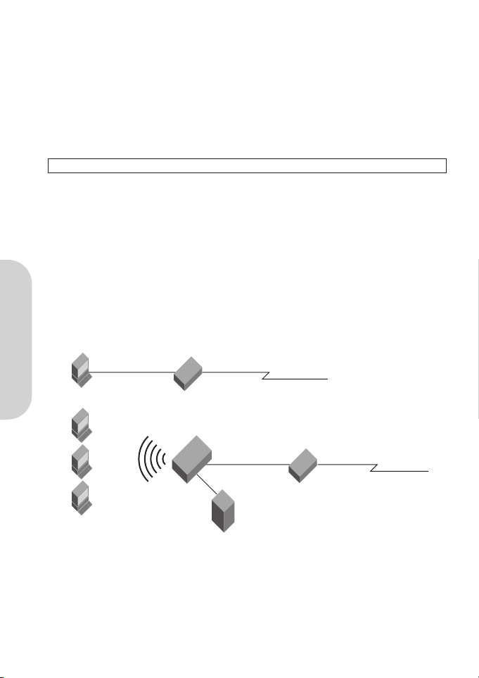
2.1 Prepare your network information
Before setting up your BAR-WL Wireless Router, it is suggested you complete the table below with the necessary information which
should be supplied by your ISP.
Computer
Computer
Existing Ethernet
Connection
External
Power Adapter
ADSL/Cable Modem
Corega
BAR WL
WAN Connection
Existing Ethernet
Connection
WAN Connection
ADSL/Cable Modem
Page 10
ENGLISH
8
Provided by some ISPs Host Name:
Domain Name:
IP address given by ISP: Dynamic IP Address
Fixed (Static) IP Address:
Subnet Mask:
Default Gateway:
DNS Server Primary:
DNS Server Secondary:
DNS Server Third:
PPP authentication: Login Name:
Password:
WAN Connection Type: Dynamic IP (DHCP):
Fixed (Static ) IP:
PPPoE:
2.2 Web-based User Interface
Your Broadband Wireless Router is designed to use a Web-based Graphical User Interface for configuration. Bring up your web
browser and type http://192.168.1.1 in the browser’s address box. This address is the factory default IP Address of your BAR-WL
Wireless Router. Press “Enter”.
Note! Your computer must have a compatible IP address.
If your computer is using Dynamic IP address, it will have a compatible IP address given to it by the BAR-WL router. (You may
have to reboot the router, then the PC for this to occur).
If your computer is using a Fixed (Static) IP address, then you will have to manually program the computer to have a compatible
IP address – see Appendix A.
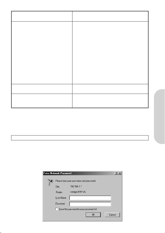
The “Username and Password Required” prompt box will appear. Leave the Username and Password empty (default) and
click “OK”.
Page 11
ENGLISH
9
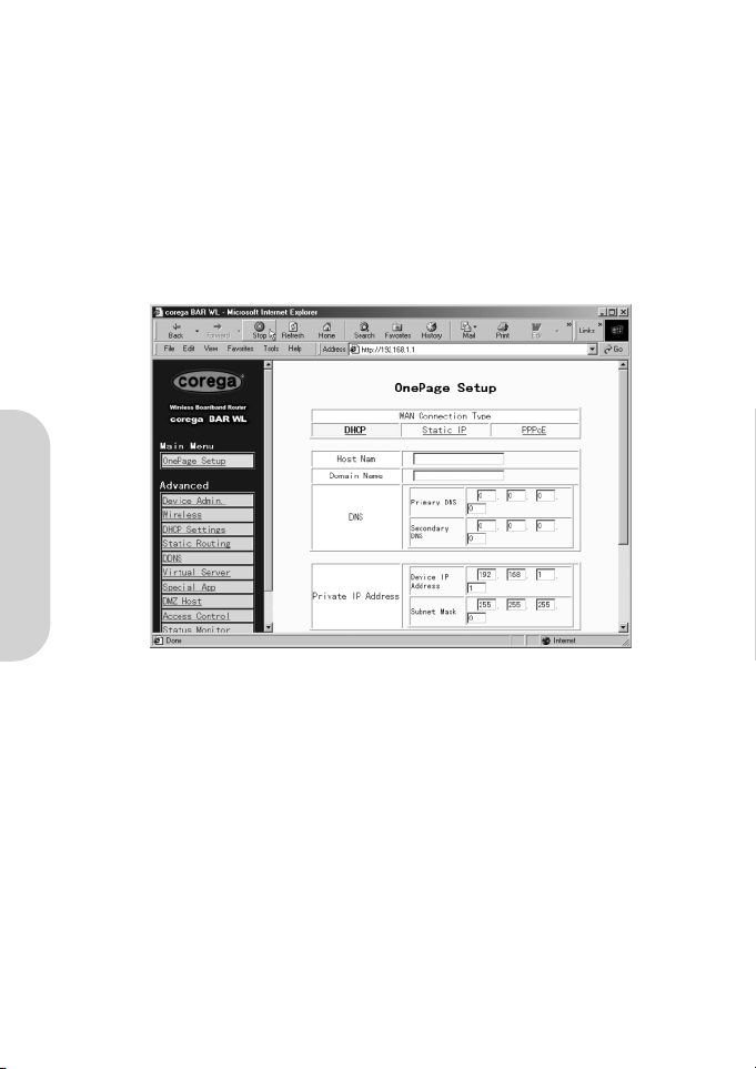
2.3 Initial Configuration – Setup
The “OnePage Setup” screen is the first screen you will see when you access the Router Configuration Wizard. If the router has
already been successfully installed and set up, this screen’s values will already be properly configured.
From the “OnePage Setup” screen, the user needs to select the operating mode of the WAN connection of the router. This can
be one of three choices:
• DHCP
• Static (Fixed) IP
• PPPoE
If you don’t know which connection type you currently use, call your ISP to get the information.
2.3.1 OnePage Setup with DHCP WAN
• Host Name
This entry is required by certain ISPs.
• Domain Name
This entry is required by certain ISPs.
• Domain Name Server (DNS)
Your ISP will provide you with at least one DNS IP Address. Multiple DNS IP settings are common. The first available DNS
entry is used in most cases.
• Private IP Address
This is the LAN IP address of the Router. This is the address that is used to configure the router. The default values are:
192.168.1.1 for IP Address and
255.255.255.0 for Subnet Mask.
• Wireless
Check “Enable” or “Disable” to make the wireless LAN function active or inactive.
Page 12
ENGLISH
10
• ESSID (Extend Service Set Identifier)
ESSID is the unique name shared among all clients and the BAR-WL Wireless Router in a same wireless network. The ESSID
must be identical for all wireless devices and must not exceed 32 characters. The default value for the ESSID is ‘corega’.
• Channel
Select the appropriate channel number from the drop-down. The permissible channels are different from Regulatory Domains.
Make sure that all points in the same wireless network use the same channel.
• WEP (Wired Equivalent Privacy)
WEP is an encryption mechanism used to protect your wireless data communications. WEP uses a combination of 64-bit/128bit keys to encrypt data that is transmitted between all points in a wireless network to insure data security. To code/decode
the data transmission, all points must use the identical key. To make the WEP encryption active or inactive, select
“Mandatory” or “Disable”.
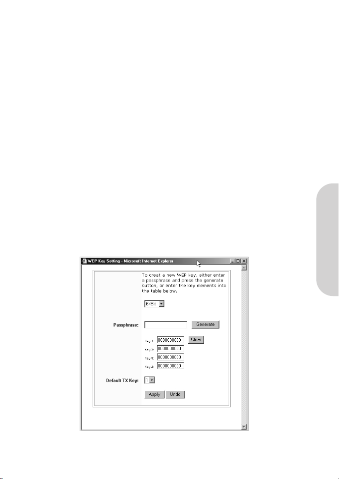
• WEP Key Setting
If WEP is set to mandatory, click the button of “WEP Key Setting” to go to the next setting screen. Select either “64Bit” or
“128Bit” encryption algorithm from the drop-down list. There are two ways to generate WEP key:
1. Passphrase
Enter an alphanumeric text string in this column then click the “Generate” button. Four 64-bit encryption keys or one
128-bit encryption key will be created automatically.
2. You can enter the WEP key manually.
You may need to enter the WEP key manually to join the existing wireless network. If you are not sure which way to use,
check with your network administrator.
• Default TX Key
If using WEP64, then select one of the four encryption keys you are going to use in the wireless network. Ensure that all the
points in a same wireless network have to have the same encryption key.
• Click “Apply” after making any changes.
Page 13
ENGLISH
11
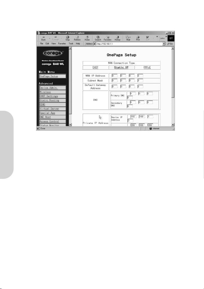
2.3.2 OnePage Setup with Static IP on the WAN
In this mode, the Public IP Address and Subnet Mask of the router are used by external users of the Internet (including your ISP).
• Specify WAN IP Address
Enter the IP address provided by your ISP.
• Subnet Mask
Enter the subnet mask values provided by your ISP.
• Default Gateway IP Address
Your ISP will provide you with the Default Gateway IP Address. This is sometimes called the ‘Next-hop’.
• Domain Name Server (DNS)
Your ISP will provide you with at least one DNS IP Address. Multiple DNS IP settings are common. The first available DNS
entry is used in most cases.
• Private IP Address
This is the LAN IP address of the Router. This is the address that is used to configure the router. The default values are:
192.168.1.1 for IP Address and
255.255.255.0 for Subnet Mask.
For setting up of the wireless, see section 2.3.1
Page 14
ENGLISH
12
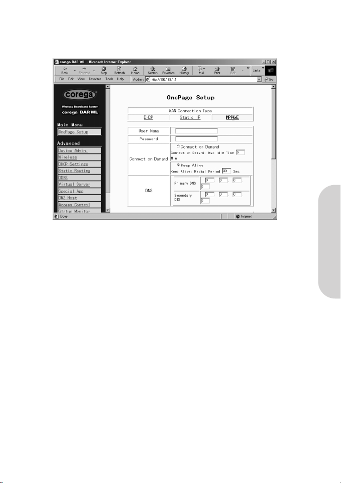
2.3.3 OnePage Setup with PPPoE on the WAN
PPPoE is a dial-up type connection type provided by some ISPs. Note that if you select PPPoE, please remove any existing PPPoE
applications on any PCs on your LAN.
• User Name
Enter the user name your ISP provide to you.
• Password
Enter the password your ISP provide to you.
• Connect-on-demand
Is a utility to trigger the PPPoE session when it is on disconnection status and there is packet being going out through WAN
port. Check the “Connect on Demand” box to make this function active, and you can enter the number of how many
minutes you wish to disconnect after network is idled in the “Max Idled Time” location. This is only used with the ISP bills
per megabyte or per second of useage.
• Keep Alive
This function keeps your PPPoE connection alive even if there is no data to transmit. However, in some situations, PPPoE
sessions cannot be re-connected immediately after a disconnection because the system on ISP site may need a little time to
restore. You may need to check your ISP to get the information that how much time it need to wait before the router start to
re-build the PPPoE session and fill it in the “Redial Period”.
• Domain Name Server (DNS)
Your ISP will provide you with at least one DNS IP Address. Multiple DNS IP settings are common. The first available DNS
entry is used in most cases.
• Private IP Address
This is the LAN IP address of the Router. This is the address that is used to configure the router. The default values are:
192.168.1.1 for IP Address and
255.255.255.0 for Subnet Mask.
For setting up of the wireless, see section 2.3.1
Page 15
ENGLISH
13
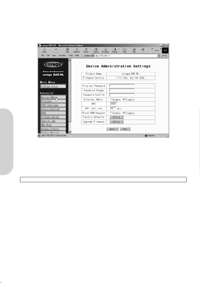
2.4 Device Administration Settings
This feature allows the administrator to manage the router by setting certain parameters. For security reasons, it is strongly recommended that you set the Password so that only authorized persons are able to manage this router. If the Password is left
blank, all users on your network can access this router simply by entering the unit’s IP Address into their web browser’s location
window.
• Firmware Version
This is a read only field which shows the installed version of the firmware.
• Changing the password
The password of the BAR-WL Wireless Router can be changed from the default (blank), or from a previously set password, by
typing the present password into the ‘Original Password’ field, and the new password into the ‘Password Change’ and
‘Password Confirm’ fields. Be sure that the password is less than 64 characters long and without any spaces.
Note! BAR-WL Router Username is always left blank.
• External Admin
Setting this to ‘Enable’ will allow users on the WAN port to manage the router. Default for this is Disabled.
• MTU (Maximum Transmission Unit)
MTU sets the maximum incoming and outgoing packet size. Enter the maximum packet size you wish to set. Default is 1500
bytes. (Recommendation for PPPoE is to set this to 1492 bytes).
• NAT Idle Time
This is the amount of time the router will wait for a response before an entry is deleted from the NAT table. Default is
10mins, and users are recommended to leave the default value.
• Factory Defaults
Select “Activate” if you want to return all the router’s current settings to their factory default settings.
• Upgrade Firmware
Select “Activate” if you want to upgrade the firmware on the router. The router will ask you to browse to the new firmware
file, which can then be uploaded.
Click “Apply” after making any changes.
Page 16

ENGLISH
14
2.5 Wireless
This setting page allows you to configure more advanced wireless functions.
• TX Rates
Select either 1~2 Mbps or 1~2~5.5~11Mbps auto fallback.
• Authentication Type
Select either Open System or Share Key as authentication type. If you are not sure, select Auto.
• Station MAC Filter
The router can block non-specific MAC addresses from connecting via the wireless LAN. To enable this filter, select ‘Enable’.
• Active MAC Table
This shows a list of all the active MAC addresses attached to the wireless LAN.
• Edit MAC Filter Settings
This screen allows the user to enter the MAC addresses of the computers which are to be allowed access to the wireless LAN.
Each individual MAC address can be filtered if required by selecting the Filter button.
Click Apply after making any changes.
Page 17
ENGLISH
15
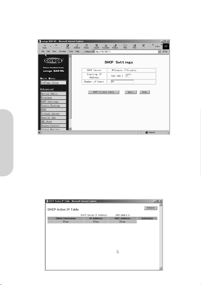
2.6 DHCP Configuration
A DHCP (Dynamic Host Configuration Protocol) Server can automatically assign IP Addresses to each computer in your network on
the LAN ports. Unless you already have a DHCP Server in you LAN, it is highly recommended that you set your router to act as a
DHCP server.
• Dynamic Server
Select “Enable” to use the DHCP server option of the router. If you already have a DHCP server in your network, set the
router's DHCP option to “Disable”.
• Starting IP Address
Enter a numerical value, from 2 to 254, for the DHCP server to start at when assigning IP Addresses.
• Number of Users
Enter the maximum number of PCs that you want the DHCP server to assign IP Addresses to, with the absolute maximum
being 253.
• DHCP Clients List
This list shows the IP addresses that have been issued by the BAR-WL Wireless Router.
Page 18
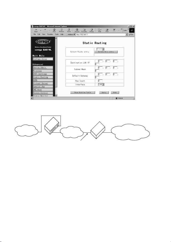
2.7 Static Routing
Only users with an excellent understanding of router protocols should attempt to change settings in this area.
• Select Route entry
Select the route entry number from 1 to 5 that you wish to configure.
• Destination LAN IP and Subnet Mask
Enter the IP Address and Subnet Mask of the destination LAN that the immediate LAN is to communicate with. Taking the
above diagram as an example, enter 192.168.2.0 in the “Destination LAN IP” field and 255.255.255.0 in the
“Subnet Mask” field.
• Default Gateway
Enter the IP Address of the router that forwards data packets to the destination LAN. For the above example,
enter 192.168.1.2 in the “Default Gateway” (Next-hop) field.
• Hop Count
Enter the number of hops required between the LANs to be connected. The Hop Count represents the “cost” of the
routing transmission. The default value is 1.
• Interface
Choose LAN if the Destination LAN is on your Router’s LAN side and choose WAN if the Destination LAN is on the
Router’s WAN side.
• Show Routing
Table Clicking this box will display the present active routes.
Click “Apply” after making any changes.
16
Router
Internet
BAR WL
Local LAN A
192.168.1.0
Default Gateway
address 192.168.1.2
Local LAN B
containing destination address
192.168.2.0
Page 19
ENGLISH
17
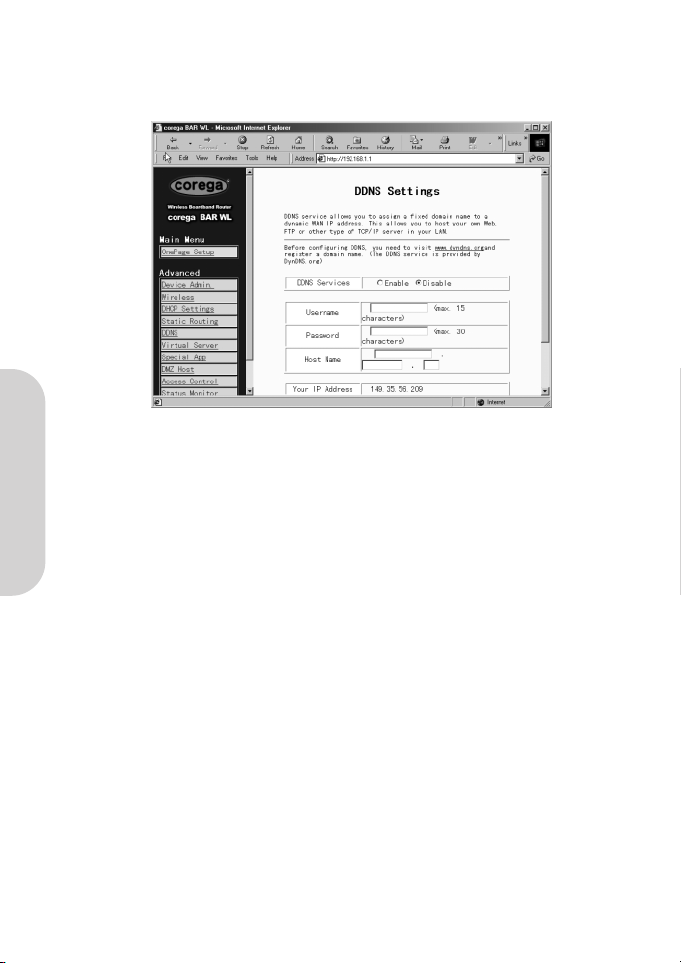
2.8 DDNS
This feature allows the router to register with a Dynamic Domain Name Server. This allows the user to host web server etc, without a fixed IP address.
• DDNS Services
Check ‘Enable’ if you wish to use this funtion. Default is ‘Disable’
• User Name
Enter your User Name provided by your DDNS provider.
• Password
Enter your Password provided by your DDNS provider.
• Host Name
Enter the your Host Name that remote users on the Internet will use to access your services.
Page 20
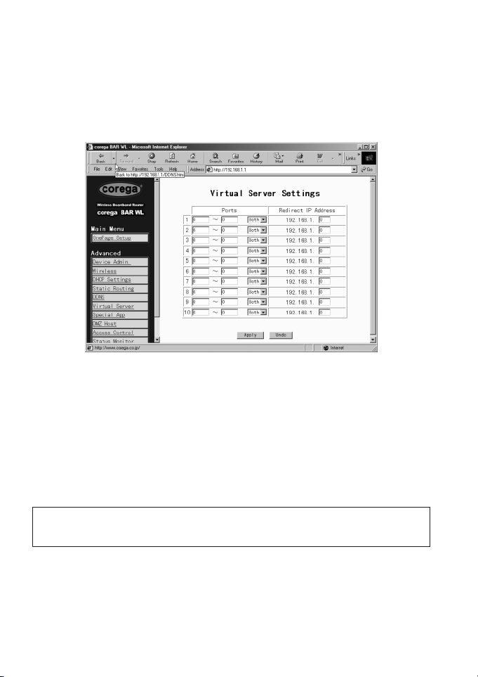
2.9 Virtual Server
The Virtual Server Settings application allows you to set up to ten public services, such as a Web Address, Email, FTP etc. that can
be accessed by external users of the Internet. Each service is provided by a dedicated network computer (server) configured with
a fixed (static) IP Address. Although the internal service addresses are not directly accessible to the external user, the BAR-WL
Wireless Router is able to identify the service requested by the service port number and redirects the request to the appropriate
internal IP Address/server. To use this application, it is recommended you use a fixed Public IP Address from your ISP. Note that
your BAR-WL Wireless Router supports only one server of any particular type.
• Set up individual network computers to act as servers and configure each with a fixed IP Address.
• In the “One Page Setup” screen, ensure the “Private IP Address” is set to the BAR-WL Wireless Router’s default setting
of 192.168.1.1. If a fixed Public IP Address is to be used, select “Specify an IP address” and enter the IP Address and
other necessary information provided by your ISP.
• Ports
Enter the desired service port numbers in the “Ports” fields. You can specify the protocol type as “TCP” or “UDP”
from the drop-down list. If you are not sure which one to select, choose “Both”. A selection of well-known service port
numbers is provided on this screen.
• Redirect IP Address
Enter the appropriate IP Addresses of the service computers in the “Redirect IP Address” locations.
Example: If the service port number 80~80 (representing an HTTP web address) is entered in “Ports” and
192.168.1.100 is entered in “Redirect IP Address”, then all HTTP requests from external Internet users
will be directed to the PC/server with the 192.168.1.100 fixed IP Address.
18
Page 21
ENGLISH
19
Here lists the protocol and port ranges that used by some common application.
Application Protocol Port Range
FTP Server TCP 21
Half Life UDP 6003, 7002, 27010, 27015, 27025
MSN Messenger TCP 6891-6900 (File-send)
TCP 1863
UDP 1863
UDP 5190
UDP 6901 (Voice)
TCP 6901 (Voice)
PC Anywhere host TCP 5631
UDP 5632
Quake 2 UDP 27910
Quake III UDP 27660 (first player)
"C:\Program Files\Quake III
Arena\quake3.exe" +set net_port 27660
27661 (second player)
Telnet Server TCP 23
Web Server TCP 80
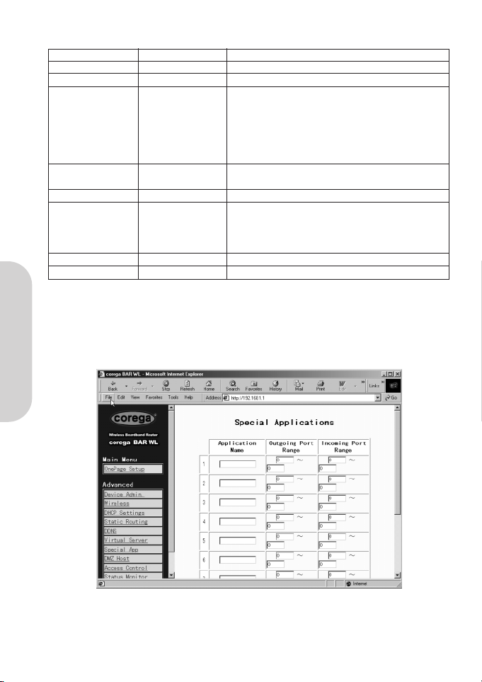
2.10 Special Applications
Some applications use multiple TCP/UDP ports to transmit data. Due to the NAT, these applications cannot work with the BAR-WL
Wireless Router. Port Triggering allows some of these applications to work properly. Note that only one PC can use each Port
Triggering setting at any time.
• Application name
Enter the name of application you wish to configure in the Name column to identify this setting. The name is for your own use
only.
Page 22
ENGLISH
20
• Outgoing Port Range
Enter the port number or range numbers this application uses when it sends packets outbound. The Outgoing Control Port
Numbers act as the trigger. When the BAR-WL Wireless Router detects the outgoing packets with these port numbers, it will
allow the inbound packets with the Incoming Port Numbers that you set in the next column to pass through the BAR-WL
Wireless Router.
• Incoming Control
Enter the port number or range numbers the inbound packets carry.
• Click “Apply” after making any changes.
Followings are port numbers list of some popular application:
Application Outgoing Control Incoming Data
Battle.net 6112 6112
DialPad 7175 51200, 51201,51210
ICU II 2019 2000-2038, 2050-2051
2069, 2085,3010-3030
MSN Gaming Zone 47624 2300-2400, 28800-29000
PC to Phone 12053 12120,12122, 24150-24220
Quick Time4 554 6970-6999
wowcall 8000 4000-4020
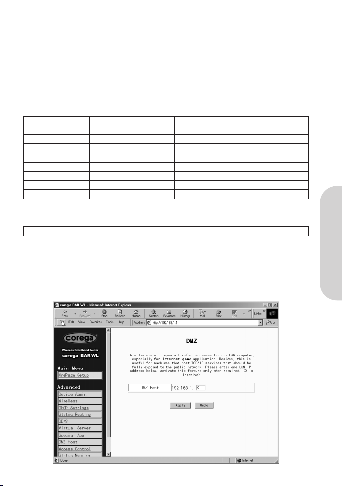
2.11 DMZ
Note! To use this application, you should obtain a Fixed (Static) Public IP Address from your ISP.
The DMZ Host application allows unrestricted 2-way communication between a single LAN PC and other Internet users or servers.
This application is useful for supporting special-purpose services such as video-conferencing and gaming, that require proprietary
client software and/or 2-way user communication.
Note that, in order to provide unrestricted access, the firewall provided by the BAR-WL Wireless Router to protect this port is
disabled, thus creating a potentially serious security risk. It is recommended that this application should be disabled when it is
not in use by entering “0” in the “DMZ Host” field.
Page 23
ENGLISH
21
1. Before setting up a LAN PC to act as a DMZ Host, configure it with a fixed IP Address.
2. In the “One Page Setup” screen, ensure the Private IP Address is set to the BAR-WL Wireless Router’s default setting of
192.168.1.1. In the Public IP Address area, select “Specify an IP Address”, then enter the IP Address and other necessary
information provided by your ISP.
3. Click “DMZ Host” from the Advanced Menu. Enter the fixed IP Address of the Exposed Host PC in the “DMZ Host” IP
Address location. Remember, entering “0” will disable this application and activate the BAR-WL Wireless Router’s firewall.
4. Click “Apply”.
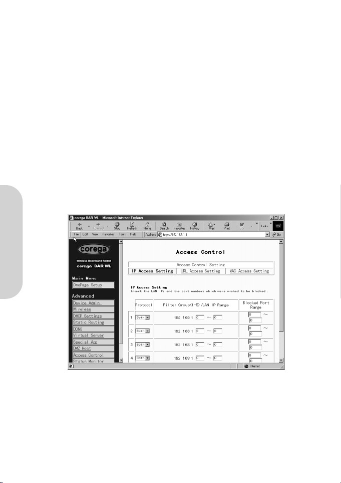
2.12 Access Control
The Access Control feature allows administrators to block certain users from accessing the Internet or specific applications. Before
using this function, the network PCs which you want to control the access limitation must be assigned fixed IP Addresses. There
are three methods of limited access:
• IP Address
• URL Access Settings
• MAC Address
2.12.1 IP Address
• Protocol
Select the protocol type as “TCP” or “UDP” from the drop down list. If you are not sure which one to choose, select
“Both”.
• Filter Group/LAN IP Range
Enter the range of IP addresses which you want them to be a controlled group to have the same access limitation.
• Block Port Range
Enter the range of port numbers which are used by the applications you wish to be blocked.
Page 24
ENGLISH
22
Here is an example of the IP Access Setting. Enter the range of 51~80 in the Filter Group column and 20~80 in the Block port
Range column, then click “Apply” button. As the result, the user’s computers which have IP Addresses in the range of
192.168.1.51 to 192.168.1.80 will not be able to use the applications which use port numbers from 20 to 80, such as FTP, Telnet
and web browsing.
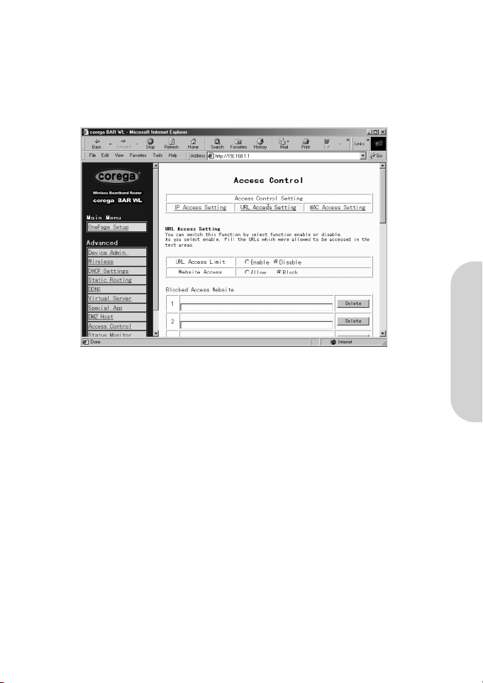
2.12.2 URL Access Setting
• URL Access Limit
Check “Enable” or “Disable” to make this function active or inactive.
• Website Access
Check “Allow” to allow users on the network to access the specific websites listed. In contrast, to restrict users on the net
work to access the website listed on the location, check “Block” in this item.
Block Access Website
Click the button of “Block Access Website” to edit the website list. Enter the website addresses to be accessed/blocked on the
locations. Up to twenty website addresses can be entered into the locations
Page 25
ENGLISH
23
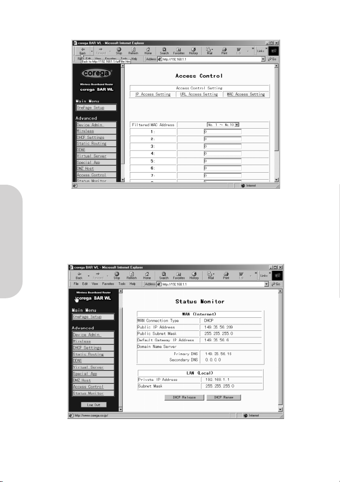
2.12.3 MAC Address Filter
• Enter the MAC addresses that you want to filter (not allow access) into the table. Click ‘Apply’ when complete. Up to 50 MAC
addresses can be filtered.
2.13 Status Monitor
This screen shows the status of the BAR-WL Wireless Router.
Page 26
ENGLISH
24
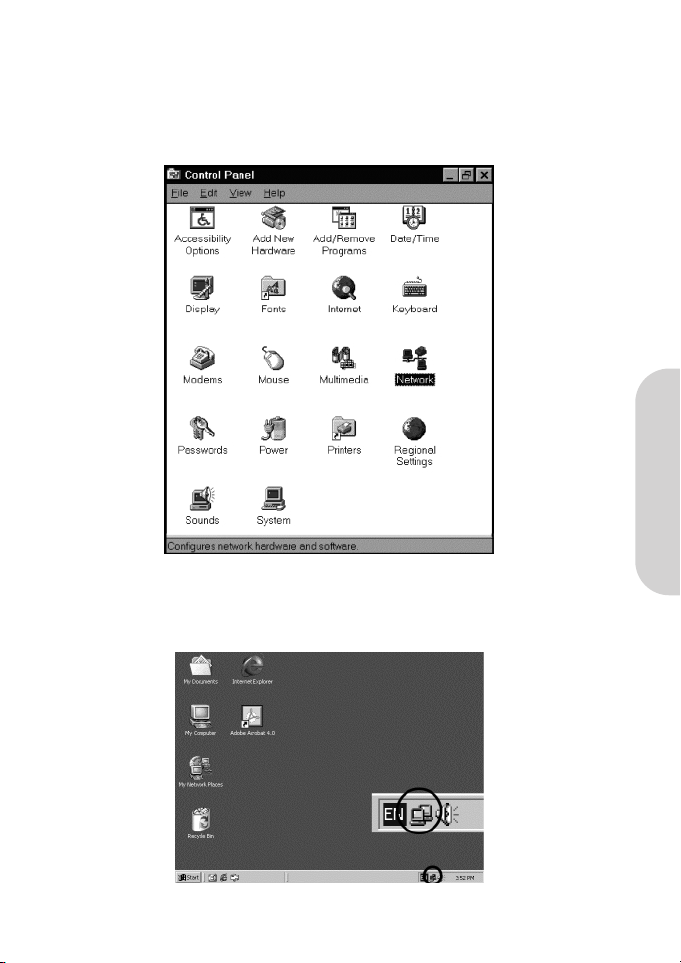
Appendix A.1 Installing the TCP/IP Protocol
If you are not sure whether the TCP/IP Protocol have been installed, follow these steps to check, and if necessary, to install
TCP/IP onto your PCs.
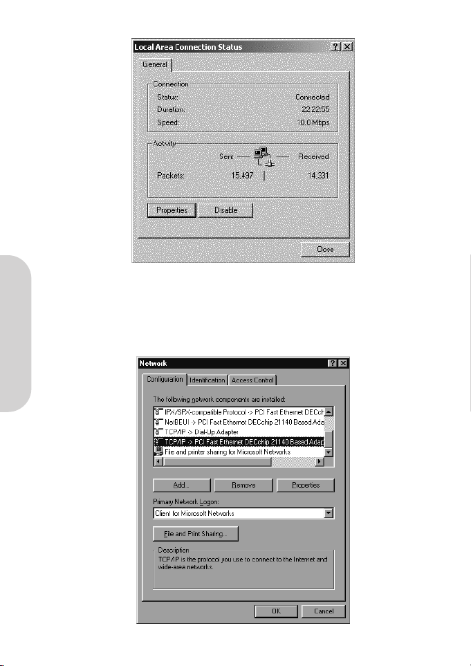
1. Click the “Start” button. Choose “Settings”, then “Control Panel”.
Double-click the “Network” icon. Your Network window should appear.
Select the “Configuration” tab.
Note: For Windows 2000 & Windows XP Setting
Click the “Local Area Connection” icon on the right bottom side of your desktop screen.
In the “Local Area Connection Status” window, click “Properties” button then your Network window will appear.
Page 27
ENGLISH
25
There is only one tab “General” in the Network window.
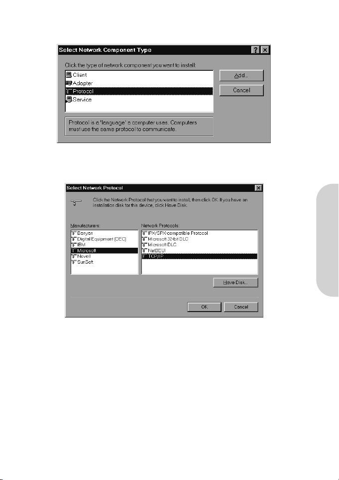
2. Check whether the TCP/IP Protocol have already been installed onto your computer’s Ethernet card. Note that TCP/IP Protocol
can be installed for a computer’s Dial-Up Adapter as well as for the Ethernet card.
- If yes, go to step 7.
- If no, click the “Add” button.
Page 28
ENGLISH
26
3. Double-click “Protocol” on the Select Network Component Type or highlight “Protocol” then click “Add”.
4. Highlight “Microsoft” under the list of manufacturers.
Double-click “TCP/IP” from the list on the right or highlight “TCP/IP” then click “OK” to install TCP/IP.
5. After a few seconds, you will be brought back to the Network window. The TCP/IP Protocol should now be on the list of
installed network components (see 2 above).
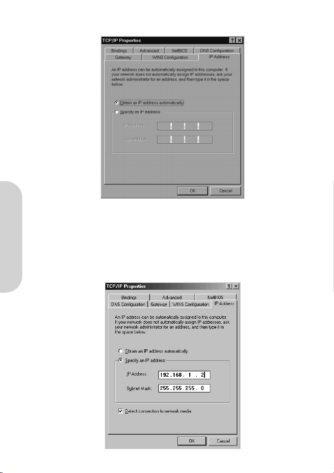
6. Click the “Properties” button.
The TCP/IP Properties window consists of several tabs. Choose the “IP Address” tab.
Page 29
ENGLISH
27
7. Select “Obtain an IP address automatically”. Click “OK”. Restart your PC to complete the TCP/IP installation.
Appendix A.2 Fixed (Static) IP Addresses Configuration
Fixed (Static) IP addresses may be assigned to network devices for many reasons, such as the server PCs or printers which are
consistently accessed by multiple users. To set up computers with Fixed (Static)IP Addresses, go to the “IP Address” tab of the
“TCP/IP Properties” window as showing above.
1. Select “Specify an IP address” and enter “192.168.1.***” in the “IP Address” location (where *** is a number
between 2 and 254 used by the BAR-WL Wireless Router to identify each computer), and the default “Subnet Mask”
255.255.255.0”. Note that no two computer on the same LAN can have the same IP address.
Page 30
ENGLISH
28
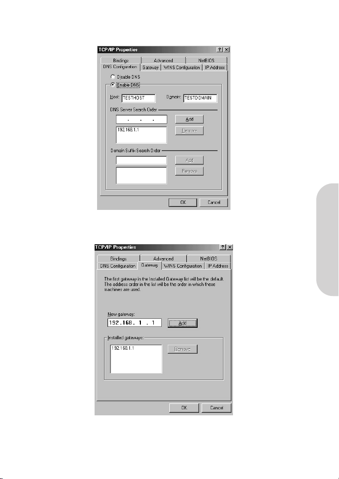
2. Select “Enable DNS” in the “DNS Configuration” tab and enter the “DNS IP Address” obtained from your ISP in the
“Server Search Order” location. Click “OK”.
3. Click “Gateway” tab and enter the Broadband Wireless Router’s default gateway value 192.168.1.1in the
“New gateway” field, then click “Add” Button.
4. Click “OK”. Restart your PC to complete the TCP/IP installation.
Page 31

DEUTSCH
29
Inhalt
Technische Daten 30
FCC Interference Statement 31
CE-Emblem – Sicherheitshinweis 31
Funktionsmerkmale 32
1. Installation des BAR-WL Routers 32
1.1 Packungsinhalt 32
1.2 LEDs auf der Front des Geräts 33
1.3 Geräterückseite und Anschlüsse 33
1.4 Vor dem ersten Verbindungsaufbau 34
1.5 Systemanforderungen und Setup 35
1.6 Installation des BAR-WL Wireless Router 35
2. Internetzugang 35
2.1 Vorbereiten der Provider- und Netzwerksinformationen 35
2.2 Web-Basierte Konfigurationsoberfläche 36
2.3 Basiskonfigiuration – Setup 37
2.3.1 “OnePage Setup” mit DHCP WAN 37
2.3.2 “OnePage Setup” mit statischer WAN-IP-Addresse 39
2.3.3 “OnePage Setup” mit PPPoE-WAN-Verbindungen 40
2.4 “Device Administration Settings” - Einstellungen für die Gerätekonfiguration 41
2.5 Wireless 42
2.6 “DHCP Settings” - DHCP-Konfiguration 43
2.7 “Static Routing” – Statisches Routing 44
2.8 DDNS 45
2.9 Virtual Server 46
2.10 Spezielle Anwendungen (Special Applications) 47
2.11 DMZ 48
2.12 Zugriffskontrolle (Access Control) 49
2.12.1 IP-Addresse (IP Address) 49
2.12.2 URL Zugriffseinstellungen (URL Access Setting) 50
2.12.3 Filder für MAC-Addressen (MAC Address Filter) 51
2.13 Statusanzeige (Status Monitor) 51
Anhang A.1 Installation des TCP/IP Protokolls 52
Anhang A.2 Konfiguration einer statischen IP-Addresse 55
Page 32

DEUTSCH
30
Größe
175 (L) x 117 (B) x 32 (H) mm
Gewicht
378g
Netzwerksanschlüsse
1 x RJ45 10BaseT/100BaseTX WAN port (Auto MDI/MDIX)
4 x RJ45 10BaseT/100BaseTX LAN ports (Auto MDI/MDIX)
Unterstützte Standards
IEEE 802.3 10BASE-T
IEEE 802.3u 100BASE-TX
IEEE 802.11b Wireless
IEEE 802.3x Flow control
Antenne
Extern
Frequenzbereich
2.4-2.497GHz
DSSS- Direct Sequence Spread Spectrum
Kanäle
11 Kanäle (USA, Kanada)
13 Kanäle (Europa)
14 Kanäle (Japan)
Datenübertragungsraten
11Mbps / 5.5Mbps / 2Mbps / 1Mbps Automatisches Wählen der
besten Methode
Zugriffsmethoden
Infrastructure-Modus
Datensicherheit
Ermöglicht 64-bit und 128-bit WEP Verschlüsselung.
Sendeleistung
18dBm
Empfangsempfindlichkeit
84dBm@11M
Reichweite
In Räumen: Bis zu 50m (165 ft.) bei 11Mbps
Bis zu 80m (265 ft.) bei 5.5Mps oder weniger
Im Freien: Bis zu 150m (500 ft.) bei 11Mbps
Bis zu 300m (1000 ft.) bei 5.5Mps oder weniger
(Abhängig von der Umgebung)
Konfiguration
Web-Basierte Konfigurationsumgebung
Betriebsumgebung
Betriebstemperatur: 0 bis 40 °C
Lagerungstemperatur: -20 bis 60 °C
Luftfeuchtigkeit: max. 90%, nicht kondensierend
Externe Spannungsversorgung
5VDC, 2.5A
Behördliche Genehmigungen
FCC Class B
CE Class B
GOST
Garantie
2 Jahre
TECHNISCHE DATEN
Page 33

DEUTSCH
31
RICHTLINIENKONFORMITÄT
FCC Interference Statement
Diese Ausrüstung wurde geprüft und als konform mit den Richtlinien für ein digitales Gerät der Klasse B entsprechend Teil 15 der
FCC-Richtlinien befunden. Diese Richtlinien dienen dem angemessenen Schutz gegen Funkstörungen bei der Installation im
Wohnbereich. Diese Ausrüstung erzeugt und verwendet Funkfrequenzenergie und kann diese ausstrahlen. Ihre nicht dieser
Anleitung entsprechende Installation und Verwendung kann Störungen des Funkverkehrs verursachen. Es kann jedoch keine
Garantie für einen fehlerfreien Betrieb in jeder Betriebsumgebung gegeben werden. Falls diese Ausrüstung eine Störung des
Rundfunk- oder Fernsehempfangs verursacht, was durch das Aus- und Einschalten der Ausrüstung ermittelt werden kann, wird der
Betreiber gebeten, diese Störung durch eine der folgenden Maßnahmen zu beheben:
• Neuausrichtung oder Verlegung der Empfangsantenne.
• Vergrößerung des Abstands zwischen Ausrüstung und Empfänger.
• Anschluss der Ausrüstung an eine Steckdose an einen anderen, nicht vom Empfänger verwendeten Stromkreis (z.B. in einem
anderen Raum).
FCC-Emissionshinweis (Federal Communications Commission)
Diese Ausrüstung ist konform mit den FCC-Grenzwerten für nicht kontrollierte Umgebungen.
Sie sollte so installiert und betrieben werden, dass ein minimaler Abstand von 20cm zwischen der Strahlungsquelle und Ihrem
Körper gewährleistet ist.
CE-Emblem – Sicherheitshinweis
Dieses Produkt ist konform zu den elektromagnetischen Spezifikationen der EN 55022/A1 Klasse B und EN 50082-1. Dies stimmt
mit der Direktive für elektomagnetische Kompatiblität der europäischen Kommission (89/336/EEC) überein.
Page 34

DEUTSCH
32
1. Installation des BAR-WL Routers
Dieser Abschnitt beschreibt das Auspacken, Einrichten und Anschliessen des BAR-WL Wireless Routers.
1.1 Packungsinhalt 1 x BAR-WL Wireless Router
1 x Netzadapter
1 x Wandmontageset (2 Schrauben und 2 Dübel)
4 x Selbstklebende Gummifüsse
1 x Vertikale Desktopeinheit
1 x Ethernetkabel
1 x Installationsanleitung
Funktionsmerkmale
Ihr BAR-WL Wireless Router ermöglicht:
• Mehreren Benutzern die Nutzung einer einzigen öffentlichen IP-Addresse zur selben Zeit.
• Kommunikation zwischen Etherrnet-LAN und Wireless-LAN über eine “wireless-to-wire bridge”.
• Unterbreichungsfreie Wireless-Anbindung, automatische Auswahl des besten Access Points, Paketflusskontrolle sowie
Netwerksfilterung
• 64 bit / 128 bit WEP-Verschlüsselung (Wired Equivalent Privacy) für sichere Wireless-Verbindungen.
• Vollständige Unterstützung von 802.11 Verschlüsselungsautentifikation “open” und “shared”
• Vier Switch-Ports, 10/100BASE-T/TX, automatische Erkennung (auto-sensing).
• NAT, um Computern im LAN den Zugang zum Internet über eine einzige IP-Addresse zu ermöglichen.
• PPPoE zum Aufbau von DSL-Einwahlverbindungen zum Internetprovider.
• Integrierte Web-basierte Konfigurationsoberfläche um eine einfache Einrichtung und Administration zu gewährleisten.
• DHCP-Unterstzung um eine statische oder dynamische IP-Addresse vom Internetprovider zu empfangen.
• Integrierter DHCP-Server für automatische IP-Addresszuweisung im LAN.
• Zugriff auf bestimmte Websiten für bestimmte Benutzer unterbinden.
• “Virtual Server”, um Benutzern aus dem Internet Zugriff auf bestimmte Funktionen oder Dienste des LAN zu gestatten.
• Uneingeschränkte zwei-Wege-Kommunikation zwischen einem PC des LAN und Diensten des Internets, wie Video- und
Konferenzsoftware oder Spiele.
Page 35

DEUTSCH
33
1.2 LEDs auf der Front des Geräts
Die folgende Grafik zeigt eine Frontansicht des BAR-WL Wireless Routers.
• PWR (Power) Grün Leuchtet bei Spannungsversorgung
• DIAG (Diagnose) Rot Leuchtet während des Selbsttests. Leuchtet nicht im normalen Betrieb.
• WLAN (Wireless LAN)
Bereitschaft: Grün Leuchtet wenn ein Access Point verfügbar ist.
Aktivität: Grün Blinkt, wenn Daten über das Wireless LAN transferiert werden.
• WAN (WAN port)
Verbindung: Grün Leuchtet, wenn ein ADSL/WAN-Gerät korrekt angeschlossen ist.
Aktivität: Gelb Blinkt, wenn Daten über den WAN-Port transferiert werden.
• LAN (LAN ports)
Link/Act: Grün Leuchtet bei einer 100 MBit-Verbindung
Gelb Leuchtet bei einer 10 MBit-Verbindung
Grün/Gelb Blinkt bei Datentransfers über den LAN-Port
• FD/Col: Grün Leuchtet im Full-Duplex-Betrieb
Leuchtet nicht im Half-Duplex-Betrieb
Blinkt, wenn eine Kollision auf dem Port stattfindet.
1.3 Geräterückseite und Anschlüsse
Die folgende Grafik zeigt die Rückansicht des BAR-WL Wireless Routers.
• Init Ein schnelles Drücken dieses Knopfes führt einen Reboot des Geräts durch. Wird der Knopf länger als 3 sekunden
gedrückt wird die Konfiguration des Routers gelöscht und in die Fabrikseinstellungen zurückgesetzt.
• WAN Dieser Port dient dem Anschluss eines ADSL- oder Kabelmodems
• LAN 1-4 Diese Ports dienen dem Anschluss vvon Computern und anderen Netzwerksgeräten an den BAR-WL.
• Power Hier wird das Netzgerät angeschlossen.
Power WAN 1 2 3 4 Init
Power
Link
Act
100M
Link/Act
Col/Fdx
1
LANWANWLAN
2 3 4
Page 36

DEUTSCH
34
1.4 Vor dem ersten Verbindungsaufbau
Corega empfielt den Download Provider-spezifischer Informationen und Installationsanweisungen von der Corega-Website vor dem
ersten Verbindungsaufbau mit dem BAR-WL. Diese Anleitungen beschreiben im Detail die Konfiguration bestimmter
Providereinstellungen.
www.corega-international.com
Wählen Sie links unten als Sprache “Deutsch”.
Klicken Sie dann unter “Support / Drivers” die “datenbank” an.
• Wählen Sie BAR-WL als Produkt-Unterkategorie von Wireless und tippen Sie den Namen ihres Providers in das Textfeld ein.
• Klicken Sie auf Suchen.
In weiterer Folge empfiehlt Corega die Website Ihres Internetproviders zu besuchen, um weitere Informationen über die Art Ihrer
Verbindung zu erhalten und ggf. Auszudrucken.
Einige Internetprovider erfordern die Angabe einer MAC-Addresse. Diese MAC-Addresse steht auf der Unterseite des Geräts und schaut
zum Beispiel so aus:
000941 2E2ACB
Page 37

DEUTSCH
35
1.5 Systemanforderungen und Setup
Um eine Verbindung mit dem Internet herzustellen, wird ein ADSL- oder Kabelmodem, sowie ein gültiger Account bei einen Provider
benötigt. Um den Router effektiv zu nutzen sollte jeder Computer folgendes unterstützen:
• Ethernet Netzwerkskarte (10Base-T oder 10/100Base-T/TX) oder Wireless-Netzwerksanbindung
• Betriebssystem: Windows 95, Windows 98, Windows NT4.0, Windows 2000, oder Windows XP.
• TCP/IP Netwerksprotokoll.
• Internet-Browser, zum Beispiel Netscape Navigator 6.0 oder höher, oder Internet Explorer 4.0 oder höher.
Anmerkung! Falls TCP/IP noch nicht auf Ihrem Computer installiert ist, lesen Sie bitte Anhang A bevor Sie mit der
Einrichtung fortfahren
1.6 Installation des BAR-WL Wireless Router
Corega empfiehlt, das die erste Einrichtung des BAR-WL durch das Verbinden eines Computers mit einem der LAN-Ports erfolgt. Bitte
versuchen Sie keine Ersteinrichtung über Wirelessanbindung!
1. Schliessen Sie alle vorhandenen Internetverbindungen auf dem PC.
2. Verbinden Sie den “WAN”-Port des Routers mit dem ADSL- oder Kabelmodem mittels des Originalkabels.
3. Verbinden Sie den PC mit dem BAR-WL über das mitgelieferte Ethernet-Kabel.
4. Schliessen sie den Netzadapter an.
5. In den meisten Fällen benötigt der PC eine dynamische IP-Addresse, welche er vom BAR-WL Router nach einem Neustart des PCs
zugewiesen bekommt. Um den Router zu konfigurieren, starten Sie einen Webbrowser und tippen Sie http://192.168.1.1 als
Addresse ein. Falls der Verbindungsaufbau fehlschlägt, prüfen Sie bitte die TCP/IP-Konfiguration Ihres PCs und lesen sie Anhang A.
2. Internetzugang
Dieses Karpitel beschreibt was notwendig ist, um eine grundlegende Konfiguration des BAR-WL Wireless Routers vorzunehmen.
2.1 Vorbereiten der Provider- und Netzwerksinformationen
Bevor Sie mit der Einrichtung beginnen, sollten Sie einige Informationen über Ihren Internetprovider zusammentragen:
Vorhandene
Ethernet-Verbindung
WAN-Verbindung
Computer
Computer
ADSL-/Kabelmodem
Corega
BAR WL
Externes Netzteil
Vorhandene
Ethernet-Verbindung
ADSL-/Kabelmodem
WAN-Verbindung
Page 38

DEUTSCH
36
Bereitgestellt von einigen Providern: Host Name:
Domain Name:
Vom Provider zugewiesene IP-Addresse: Dynamische IP-Addresse:
Statische (fixe) IP-Addresse:
Netzwerksmaske:
Default Gateway:
DNS-Server Primary:
DNS-Server Secondary:
DNS-Server Third:
Zugangsdaten: Benutzername:
Passwort:
WAN-Verbindungstyp: Dynamische IP (DHCP):
Statische IP:
PPPoE:
2.2 Web-Basierte Konfigurationsoberfläche
Ihr Router bietet Ihnen eine Web-Basierte graphische Oberfläche für die Konfiguration. Starten Sie einen Web-Browser, und tippen Sie
http://192.168.1.1 als Addresse ein. Diese Addresse ist die Standard-IP-Addresse des Routers. Drücken Sie “Enter”.
Anmerkung! Ihr Computer muss eine IP-Addresse im selben Bereich besitzen.
Falls Ihr Computer dynamische IP-Zuweisung verwendet, erhällt er eine Addresse vom BAR-WL Router. (Sie müssen unter Umständen
neustarten).
Falls Ihr Computer eine statische IP-Addresse besitzt, müssen Sie manuell eine korrekte Addresse eingeben (siehe Anhang A).
Das “Benutzername und Passwort erforderlich”-Fenster erscheint. Lassen Sie beide Textfelder frei (Standardeinstellung) und
drücken Sie auf “OK”.
Page 39

DEUTSCH
37
2.3 Basiskonfigiuration – Setup
Die “OnePage Setup”-Seite ist die erste Seite die Sie sehen, wenn Sie auf die Router-Konfiguration zugreifen. Falls der Router
bereits korrekt eingerichtet wurde, stimmen die Angaben auf dieser Seite.
In der “OnePage Setup”-Seite müssen Sie die Betriebsart des WAN-Anschlusses auswählen. Sie haben die Wahl zwischen:
• DHCP
• Static (Fixed) IP
• PPPoE
Falls Sie nicht wissen welcher Eintrag erforderlich ist, kontaktieren Sie Ihren Internetprovider.
2.3.1 “OnePage Setup” mit DHCP WAN
• Host Name
Ist bei einigen Providern erforderlich.
• Domain Name
Ist bei einigen Providern erforderlich.
• Domain Name Server (DNS)
Ihr Provider stellt Ihnen einen oder mehrere DNS-Server zur Verfügung. Falls Sie mehrere Addressen zur Verfügung haben, wird
meist der erste Eintrag verwendet.
• Private IP Address
Dies ist die LAN-IP-Addresse des Routers. Das ist auch die Addresse, über die der Router konfiguriert wird Die
Standardeinstellungen sind:
192.168.1.1 als “IP Address” und
255.255.255.0 als “Subnet Mask”.
• Wireless
Wählen Sie “Enable” oder “Disable” um die Wireless-LAN Funktion ein- oder auszuschalten.
Page 40

DEUTSCH
38
• ESSID (Extend Service Set Identifier)
Die ESSID ist der Name des Wireless-Netzwerks, der auf allen Wireless-Geräten die untereinander kommunizieren wollen gleich
sein muss. Er darf nicht länger als 32 Zeichen sein. Standardwert ist “corega”.
• Channel
Wählen Sie einen Kanal aus dem Dropdownmenü. Die Anzahl wählbarer Kanäle variiert nach Region. Alle Wireless-Geräte die
miteinander kommuniezieren sollen, müssen den selben Kanal gewählt haben.
• WEP (Wired Equivalent Privacy)
WEP ist der Verschlüsselungsmechanismus für Wireless-Verbindungen. Es werden Kombinationen von 64-bit/128-bit-Schlüsseln
verwendet um sichere Übertragungen im Wireless-Netzwerk zu ermöglichen. Um am gesicherten Netzwerk teilzunehmen, muss
jedes Wireless-Gerät den selben Schlüssel benutzen. Um WEP ein- oder auszuschalten, wählen Sie “Mandatory” oder
“Disable”.
• WEP Key Setting
Wenn Sie die Auswahl “WEP” auf “Mandatory” gesetzt haben, klicken Sie auf “WEP Key Settings” um weitere Einstellungen
vorzunehmen. Sie haben weiters die Wahl zwischen “64Bit” oder “128Bit”-Verschlüsselung über das entsprechende
Dropdown-Menü. Es gibt zwei Möglichkeiten um einen WEP-Schlüssel zu generieren:
1. Passphrase
Tragen Sie eine alphanumerische Zeichenkette in diese Spalte und klicken sie auf “Generate”. Daraufhin wird entweder ein
128-bit- oder vier 64-bit-Schlüssel automatisch generiert
2. Sie können den WEP-Schlüssel manuell eintragen.
Sie können den WEP-Schlüssel manuell eintragen, um zu einem bestehenden Netzwerk zu verbinden. Falls Sie nicht wissen
welche Methode Sie verwenden müssen, konsultieren Sie Ihren Netzwerksadministrator.
• Default TX Key
Falls Sie WEP64 verwenden, können Sie hier den Standardschlüssel wählen. Stellen Sie sicher, das alle Wireless-Geräte die
miteinander kommunizieren sollen den selben Schlüssel benutzen.
• Klicken Sie auf “Apply” um die Änderungen zu übernehmen.
Page 41

DEUTSCH
39
2.3.2 “OnePage Setup” mit statischer WAN-IP-Addresse
In dieser Betriebsart werden IP-Addresse und Netzwerksmaske des Routers fix festgelegt.
• WAN IP Address
Geben Sie hier die IP-Addresse ein, die Ihnen Ihr Proivder zur Verfügung stellt.
• Subnet Mask
Geben Sie hier die Netzwerksmaske ein, die Ihnen Ihr Provider zur Verfügung stellt.
• Default Gateway IP Address
Geben Sie hier die IP-Addresse des Gateways ein, den Ihnen Ihr Provider zur Verfügung stellt. Auch als “Next Hop” bekannt.
• Domain Name Server (DNS)
Geben Sie hier eine oder mehrere (optional) DNS-Server-Addressen ein, die Ihnen Ihr Provider zur Verfügung stellt
• Private IP Address
Die LAN-IP-Addresse des Routers. Diese Addresse wird benutzt um den Router zu Konfigureren. Die Standardwerte sind:
192.168.1.1 als IP Address und
255.255.255.0 als Subnet Mask.
Für Anweisungen zur Einrichtung von Wireless lesen Sie Abschnitt 2.3.1
Page 42

DEUTSCH
40
2.3.3 “OnePage Setup” mit PPPoE-WAN-Verbindungen
PPPoE ist eine Einwahlmethode, die einige (ADSL-) Provider anbieten. Falls Sie PPPoE einrichten, entfernen Sie bitte vorhandenen
PPPoE Einwahlprogramme von den PCs ihres Netzwerks, um Konflikte zu vermeiden.
• User Name
Geben Sie hier Ihren Einwahlbenutzernamen ein.
• Password
Geben Sie hier Ihr Einwahlpasswort ein.
• Connect-on-demand
Aktivieren Sie diese Option, falls Sie wünschen, dass die Verbindung erst bei eingehendem Netzwerksverkehr aufgebaut wird und
geben Sie dann die Verzögerungszeit in “Max Idled Time” ein, nach der die Verbindung wieder beendet wird, falls die PPPoEVerbindung nicht genutzt wird. Diese Funktion ist praktisch für Provider gedacht, die nach Zeit abrechnen.
• Keep Alive
Diese Option hällt die PPPoE-Verbindung aufrecht, auch wenn keine Daten transferiert werden. In einigen Fällen kann die
Verbindung nicht sofort erneut aufgebaut werden, da der Provider Zeit zur Re-Initialisierung braucht. Sie sollten bei Ihrem
Provider anfragen wieviel Zeit vor einem erneuten Verbindungsaufbau gewartet werden Muss, und diese dann in “Redial
Period” eintragen.
• Domain Name Server (DNS)
Ihr Provider stellt ihnen eine oder mehrere (optional) DNS-Server-Addressen zur Verfügung.
• Private IP Address
Dies ist die LAN-IP-Addresse Ihres Router, über die dieser auch konfiguriert wird. Die standardwerte sind:
192.168.1.1 als IP Address und
255.255.255.0 als Subnet Mask.
Für Anweisungen zur Einrichtung von Wireless lesen Sie Abschnitt 2.3.1
Page 43

DEUTSCH
41
2.4 “Device Administration Settings” - Einstellungen für die Gerätekonfiguration
Diese Funktion erlaubt die Einrichtung des Routers auf einigen sicherheitsrelevanten Gebieten. Um Sicherheit zu gewährleisten,
empfehlen wir Ihnen ein Passwort einzustellen, um zu verhinden, dass nicht autorisierte Personen Änderungen am Router
vornehmen. Falls kein Passwort eingestellt ist, kann jeder im Netzwerk durch einfaches Eingeben der IP-Addresse auf die
Router-Konfiguration zugreifen.
• Firmware Version
Dieses Feld zeigt Ihnen die Version der Router-Firmware (schreibgeschütztes Feld).
• Changing the password
Falls noch kein Passwort definiert wurde, können Sie das gewünschte Passwort in “Password Change” und zur Versicherung
erneut in “Password Confirm” eingeben. Falls zuvor bereits ein Passwort definiert wurde das Sie ändern möchten, tippen Sie das
alte Passwort in “Original Password” ein. Achten Sie darauf das Ihr Passwort nicht länger als 64 Zeichen ist und keine
Leerzeichen enthällt.
Anmerkung! Der Benutzername des BAR-WL Routers wird immer leer gelassen.
• External Admin
Setzen Sie diese Option auf “Enabled”, um Benutzern von Aussen Zugriff auf die Konfiguration des Routers zu gestatten.
Standard ist “Disabled”.
• MTU (Maximum Transmission Unit)
MTU stellt die maximale Größe für ein- und ausgehende IP-Datenpakete da. Geben Sie hier einen Wert Ihrer Wahl ein. Das
Maximum ist 1500 Bytes, für PPPoE wird ein MTU-Wert von 1492 Bytes empfohlen.
• NAT Idle Time
Dies stellt die Wartezeit ein, die auf eine Antwort gewartet wird, bevor ein Eintrag aus der NAT-Tabelle gelöscht wird.
Standardwert ist 10mins, es ist empfohlen diese Einstellung auf dem Standardwert zu belassen.
• Factory Defaults
Wählen Sie “Activate”, wenn Sie den Router auf seine werksseitigen Standardeinstellungen zurücksetzen wollen.
• Upgrade Firmware
Wählen Sie “Activate”, falls Sie die Firmware des Routers aktualisieren wollen. Sie können dann die neue Firmware-Datei
von Ihrer Festplatte auswählen und hochladen.
Klicken Sie auf “Apply”, um die Änderungen anzuwenden.
Page 44

DEUTSCH
42
2.5 Wireless
Diese Seite ermöglicht Ihnen eine erweiterte Konfiguration der Wireless-Funktionen.
• TX Rates
Wählen Sie die gewünschte Datentransferrate aus der Liste aus (1-2 Mbit, 1, 2, 5.5, 11 Mbit oder auto fallback).
• Authentication Type
Wählen Sie “Open System” oder “Share Key” als Autentifikation. Wenn Sie sich nicht sicher sind, wählen Sie “Auto”.
• Station MAC Filter
Der Router kann nicht-spezifizierten MAC-Addressen den Zugriff verweigern. Falls Sie diese Art der Sicherung wünschen, wählen
Sie “Enable”.
• Active MAC Table
Dies zeigt Ihnen eine Liste aller momentan aktiven MAC-Addressen auf dem Wireless-Port.
• Edit MAC Filter Settings
Diese Eingabemaske ermöglicht Ihnen die Eingabe der MAC-Addressen, die Zugriff auf den Router über Wireless-LAN haben
dürfen, falls “Station MAC Filter” aktiviert wurde. Jede MAC Addresse kann herausgefilter werden durch Klicken auf “Filter”.
Klicken Sie auf “Apply” um die Änderungen vorzunehmen
Page 45

DEUTSCH
43
2.6 “DHCP Settings” - DHCP-Konfiguration
Ein DHCP (Dynamic Host Configuration Protocol) Server kann den Computern auf den LAN-Ports automatisch die korrekten
Netwerkseinstellungen zuweisen. Solange nicht bereits einen DHCP-Server im Netwerk vohanden ist, sollten Sie den eingebauten
DHCP-Server des Routers aktivieren.
• Dynamic Server
Wählen Sie “Enable” um den DHCP-Server zu aktivieren. Falls Sie bereits einen DHCP-Server im Netzwerk betreiben, setzen Sie
diese Option auf “Disable”.
• Starting IP Address
Wählen Sie einen numerischen Wert von 2 bis 254, der den Anfangswert für die IP-Addresszuweisung festlegt.
• Number of Users
Tragen Sie hier die maximale Anzahl PCs ein, die der DHCP-Server gleichzeitig versorgen darf. Das maximum ist 253.
• DHCP Clients List
Zeigt die Liste der Clients, die vom DHCP-Server des BAR-WL konfiguriert wurden.
Page 46

DEUTSCH
44
2.7 “Static Routing” – Statisches Routing
Diese Einstellungen sollten nur von Personen mit tieferem Wissen über Routing verstellt werden.
• Select Route entry
Wählt den Routingeintrag 1 – 5 den Sie konfigurieren möchten.
• Destination LAN IP und Subnet Mask
Tragen Sie hier das IP.Netzwerk und Netzwerksmaske des Zielnetzwerks ein, mit dem vom Quellnetzwerk aus kommuniziert
werden soll. Zum Beispiel 192.168.2.0 als IP-Netzerk in das “Destination LAN IP”-Feld und 255.255.255.0 als
Netzwerksmaske in das “Subnet Mask”-Feld.
• Default Gateway
Tragen Sie die IP-Addresse des Routers ein, der die Pakete zum Zielnetzwerk weiterleiten soll. Dies kann zum Beispiel
192.168.1.2 als Eintrag ins “Default Gateway” (Next-hop) Feld sein.
• Hop Count
Tragen Sie die Anzahl der Schritte ein, die die Daten zum Zielnetzwerk zurücklegen müssen. Dies entspricht normalerweise der
Zahl der Router die sich zwischen dem BAR-WL und dem Zielnetzwerk befinden. Der Standardwert ist 1.
• Interface
Wählen Sie LAN falls das Zielnetzwerk sich im LAN-Bereich des BAR-WL befindet, oder WAN wenn sich das Zielnetz auf der
WAN-Seite des Routers befindet.
• Show Routing
Klicken Sie hier um die aktuelle Routingtabelle anzuzeigen.
Klicken Sie auf “Apply” um die Änderungen zu speichern.
Router
Internet
BAR WL
Local LAN A
192.168.1.0
Default Gateway
address 192.168.1.2
Local LAN B
containing destination address
192.168.2.0
Page 47

DEUTSCH
45
2.8 DDNS
Diese Funktion ermöglicht die Nutzung dynamischer Domain-Namen. Dies erlaubt zum Beispiel den Betrieb eines Webservers ohne
statische IP-Addresse.
• DDNS Services
Wählen Sie auf ‘Enable’ um DDNS zu aktivieren. Standard ist ‘Disable’
• User Name
Tragen Sie hier den Benutzernamen für die DDNS-Aktualisierung ein.
• Password
Tragen Sie hier das Passwort für die DDNS-Aktualisierung ein.
• Host Name
Tragen Sie hier den Hostnamen ein, unter dem Ihre Dienste erreichbar sein sollen.
Page 48

DEUTSCH
46
2.9 Virtual Server
Die Virtual-Server-Funktion ermöglicht Ihnen die Freigabe von bis zu 10 Diensten des LAN, wie Web-, Mail- oder FTP-Server für den
Zugriff aus dem Internet. Jeder Computer, dessen Netzwerksdienst von Aussen erreichbar sein soll, muss mit einer statischen IPAddresse ausgestattet sein (keine automatische DHCP-Konfiguration). Interne Dienste sind zwar prinzipiell von aussen nicht direkt
erreichbar, aber der Router kann Anfragen an diese Dienste identifizieren und an den entsprechenden lokalen Computer weiterleiten.
Um diese Funktion effektiv zu nutzen, wird es empfohlen vom Provider eine statische IP-Addresse zu beziehen oder DDNS (Siehe
Abschnitt 2.8) zu benutzen. Anmerkung: Der Router kann nur eine Weiterleitung pro Dienst zur Verfügung stellen.
• Richten Sie die Server-Dienste Ihrer lokalen Computer ein und weisen Sie jedem dieser Computer eine statische IP-Addresse zu.
• Stellen Sie sicher, dass sich die Option “Private IP Address” auf der “One Page Setup”-Seite des Routers in der
Standardeinstellung 192.168.1.1 befindet. Falls eine statische IP-Addresse verwendet werden soll, wählen Sie “Specify an IP
address” und geben Sie die IP-Addresse ebenso wie andere, vom Provider zur Verfügung gestellte Informationen ein.
• Ports Tragen Sie die gewünschten Port-Nummern in die “Ports”-Felder ein. Sie können als Protokolltyp “TCP” oder “UDP” aus
der Drop-Down-Liste wählen. Falls Sie sich nicht Sicher sind welcher Protokolltyp der richtige ist, oder beide benötigt werden,
wählen Sie “Both”.Enter the desired service port numbers in the “Ports” fields. You can specify the protocol type as “TCP” or
“UDP” from the drop-down list. If you are not sure which one to select, choose “Both”. Auf dieser Seite wird Ihnen eine auswahl
bekannter Dienste zur Verfügung gestellt.
• Redirect IP Address Tragen Sie die IP-Addresse des lokelen Ziel-Computers (Servers) in dieses Feld ein.
Beispie: Wenn die Service-Port-Nummer 80-80 (HTTP-Webserver) in “Ports” eingetragen ist, und 192.168.1.100 in
“Redirect IP Address” eingetragen ist, werden alle vom Internet eingehenden HTTP-Aufrufe an den lokalen
Computer mit der IP-Addresse 192.168.1.100 weitergeleitet.
Page 49

DEUTSCH
47
Hier ist eine Liste der Ports die einige Programme verwenden.
Programm Protokoll Verwendete Ports
FTP Server TCP 21
Half Life UDP 6003, 7002, 27010, 27015, 27025
MSN Messenger TCP 6891-6900 (Dateien versenden)
TCP 1863
UDP 1863
UDP 5190
UDP 6901 (Sprachübertragungen)
TCP 6901 (Sprachübertragungen)
PC Anywhere host TCP 5631
UDP 5632
Quake 2 UDP 27910
Quake III UDP 27660 (erster Spieler)
"C:\Program Files\Quake III
Arena\quake3.exe" +set net_port 27660
27661 (zweiter Spieler)
Telnet Server TCP 23
Web Server TCP 80
2.10 Spezielle Anwendungen (Special Applications)
Einige Anwendungen verwenden mehrfache TCP/UDP-Ports um Daten zu übertragen. Einige dieser Anwendungen könnten wegen
NAT über den Router nicht korrekt funktionieren. “Port Triggering” ermöglicht es einigen dieser Anwendungen korrekt zu arbeiten,
es kann jedoch immer nur jeweils ein Computer auf einmal im Netzwerk die “Port Triggering”-Funktion benutzen.
• Application name
Tragen Sie den Namen der Anwendung ein, die konfiguriert werden soll. Diese Option dient nur zur eigenen Information.
Page 50

DEUTSCH
48
• Outgoing Port Range
Tragen Sie die Port-Nummer oder den Port-Bereich ein, über den die Anwendung Daten versendet. Diese Ports werden als
“Trigger” verwendet. Wenn der Router feststellt das über diese Ports Datenpakete versendet werden, ermöglicht der Router den
Empfang von Daten über die in “Incoming Control” eingetragenen Ports.
• Incoming Control
Tragen Sie die Port-Nummer oder den Port-Bereich ein, über den eingehendende Daten verwertet werden sollen.
• Klicken Sie auf “Apply” um die Änderungen zu speichern.
Dies ist eine Liste der Port-Nutzung einiger populärer Anwendungen:
Anwendung “Outgoing Port Range” “Incoming Control”
Battle.net 6112 6112
DialPad 7175 51200, 51201,51210
ICU II 2019 2000-2038, 2050-2051
2069, 2085,3010-3030
MSN Gaming Zone 47624 2300-2400, 28800-29000
PC to Phone 12053 12120,12122, 24150-24220
Quick Time4 554 6970-6999
wowcall 8000 4000-4020
2.11 DMZ
Anmerkung! Um diese Funktion effektiv nutzen zu können, sollten Sie von Ihrem Provider eine statische IP-Addresse
beziehen oder die DDNS-Funktion aktivieren.
Die DMZ-Funktion gestattet eine uneingeschränkte Zwei-Wege-Kommunikation zwischen einem Computer im LAN und Diensten im
Interrnet. Dies ist für einige spezielle Einsatzgebiete, wie Video-Konferenzen und Spiele, die Zwei-Wege-Kommunikation benötigen,
gedacht.
Bedenken Sie, das für die Uneingeschränkte Nutzung die Firewall des Routers deaktiviert ist, was ein potentielles Sicherheitsrisiko
darstellt. DMZ sollte deaktiviert bleiben, falls es nicht benötigt wird, indeem “0” in das “DMZ Host”-Feld eingetragen wird.
Page 51

DEUTSCH
49
1. Bevor Sie einen LAN-Computer mit der DMZ-Funktion ausstatten, müssen Sie ihm eine statische IP-Addresse zuweisen.
2. Stellen Sie sicher das sich die Private IP-Addresse des Routers, auf der “One Page Setup”-Seite, in der Standardeinstellung
192.168.1.1 befindet. Im Bereich für die öffentliche IP-Addresse (Public ip address) wählen Sie “Specify an IP Address”, und
tragen Sie dort die IP-Addresse und andere erforderliche Informationen, die Ihnen Ihr Provider zugewiesen hat, ein.
3. Klicken Sie auf “DMZ Host” im “Advanced Menu”. Tragen Sie die statische IP-Addresse des gewünschten LAN-Computers in das
“DMZ Host”-Feld ein. Denken Sie daran: der Eintrag “0” aktiviert die DMZ-Funktion und aktiviert die Firewall des Routers.
4. Klicken Sie auf “Apply”.
2.12 Zugriffskontrolle (Access Control)
Die Zugriffskontrolle (Access Control) gestattet es dem Administrator, einigen Benutzern den Zugriff auf das Internet oder auf bestimmte Dienste zu verweigern. Bevor Sie diese Funktion einsetzen, sollten Sie den LAN-Computern die Sie einschränken wollen, statische IP-Addressen zuweisen. Es gibt drei Möglichkeiten um den Zugriff einzuschränken:
• IP-Addresse
• URL-Zugriffseinstellungen
• MAC-Addresse
2.12.1 IP-Addresse (IP Address)
• Protocol
Wählen Sie “TCP” oder “UDP” als Protokolltyp aus der Drop-Down-Liste. Falls Sie sich nicht sicher sind, welcher der Richtige ist,
oder beide benötigt werden, wählen Sie “Both”.
• Filter Group/LAN IP Range
ETragen Sie den IP-Bereich ein, dem sie in Gruppenform bestimmte gemeinsame Begrenzungen auferlegen möchten.
• Block Port Range
Tragen Sie Port-Nummern ein deren Nutzung Sie unterbinden möchten.
Page 52

DEUTSCH
50
Ein Beispiel für die IP-Zugrifsseinstellungen: Tragen Sie als Port-Bereich 51 bis 80 in die “Filter Grop”-Spalte und 20 bis 80in die
“Port Range”-Spalte ein und klicken Sie dann auf “Apply”. Das Resultat ist, dass Computer im LAN, deren IP-Addresse im Bereich
von 192.168.1.51 bis 192.168.1.80 liegt, auf Internet-Dienste wie Web-, FTP-Server und Telnet-Server nicht mehr zugreifen können.
2.12.2 URL Zugriffseinstellungen (URL Access Setting)
• URL Access Limit
Wählen Sie “Enable” (akvitieren) oder “Disable” (deaktivieren) um diese Funktion zu aktivieren oder zu deaktivieren.
• Website Access
Wählen Sie “Allow” um den Benutzern des LAN den Zugriff auf die spezifizierte Website zu gestatten. Andererseits, um
Benutzern den Zugriff auf die spezifizierte Website zu verweigern, wählen Sie “Block”.
Block Access Website
Klicken Sie auf “Block Access Website” um die Liste der Websites zu bearbeiten. Tragen Sie die Addressen der Websites ein, deren
Zugriff Sie gestatten/verweigern möchten. Es können bis zu zwanzig Addressen in die jeweiligen Felder eingetragen werden.
Page 53

DEUTSCH
51
2.12.3 Filder für MAC-Addressen (MAC Address Filter)
• Tragen Sie die MAC-Addressen ein, denen der Zugriff auf den Router verweigert werden soll. Klicken Sie auf “Apply” um die
Änderungen zu speichern. Es können bis zu 50 MAC-Addressen eingetragen werden
2.13 Statusanzeige (Status Monitor)
Diese Seite zeigt den Zustand des BAR-WL Routers.
Page 54

DEUTSCH
52
Anhang A.1 Installation des TCP/IP Protokolls
Falls Sie sich nicht sicher sind, ob Sie das TCP/IP Protokoll installiert haben, folgen Sie dieser Anleitung zur Prüfung und ggf. zur
Installation von TCP/IP auf ihren Computer.
1. Klicken Sie auf “Start”, wählen Sie “Einstellungen”, dann “Systemsteuerung”.
Doppelklicken Sie auf das “Netzwerk”-Symbol. Ein Netzwerksfenster wird erscheinen.
Wählen Sie den Abschnitt “Konfiguration”.
Anmerkung: Für Windows 2000- und Windows XP-Nutzer
Klicken Sie auf das “Netzwerksverbindungen”-Symbol rechts unten in der Task-Leiste
Im “LAN Verbindungsstatus”-Fenster klicken Sie auf “Einstellungen”, dann wird das Netzwerksfenster erscheinen.
Page 55

DEUTSCH
53
Dort befindet sich als einzige Auswahl “Allgemein”.
2. Prüfen Sie ob das TCP/IP Protokoll bereits für die Ethernet-Netzwerkskarte installiert wurde. Bedenken Sie bitte, dass das TCP/IP
Protokoll auch für andere Verbindungen (z.B. Einwahlverbindungen) als Ethernet installiert sein kann
- Falls ja, fahren Sie mit Schritt 7 fort.
- Falls TCP/IP noch nicht installiert ist, klicken Sie auf “Hinzufügen”.
Page 56

DEUTSCH
54
3. Doppelklicken Sie auf “Protokoll”, oder wählen Sie “Protokoll” und klicken Sie auf “Hinzufügen”.
4. Wählen Sie “Microsoft” aus der Herstellerliste.
Doppelklicken Sie auf “TCP/IP” in der rechten Liste, oder wählen Sie “TCP/IP” und klicken Sie auf “OK” um die Installation
abzuschliessen.
5. Nach einigen Sekunden befinden Sie sich wieder im Netzwerksfenster. Das TCP/IP-Protokoll sollte nun in der Liste aufscheinen.
6. Wählen Sie das TCP/IP-Protokoll für Ihre Netzwerkskarte und klicken Sie auf “Einstellungen”
Das TCP/IP-Fenster besteht aus einigen Tabs. Wählen Sie das “IP-Addresse”-Tab.
Page 57

DEUTSCH
55
7. Wählen Sie “IP-Addresse automatisch beziehen” und klicken Sie auf OK. Starten Sie Ihren Computer neu um die
Installation abzuschliessen.
Anhang A.2 Konfiguration einer statischen IP-Addresse
Es gibt verschiedene Gründe um einem Computer eine statische IP-Addresse zuzuweisen, zum Beispiel Server- oder DMZ-Betrieb. Um
dem Computer eine statische IP-Addresse einzustellen, gehen Sie in den “IP-Addresse”-Tab der “TCP/IP Einstellungen” wie
unten gezeigt.
1. Wählen Sie “IP-Addresse eingeben” und tragen Sie “192.168.1.???” in das “IP-Addresse”-Feld ein (??? ist eine Zahl
zwischen 2 und 254 die zur Identifikation Ihres Computers im Netzwerk dient), und als “Netzwerksmaske” tragen Sie
“255.255.255.0” ein. Bedenken Sie, dass jede IP-Addresse im Netzwerk nur einmal vorkommen darf.
Page 58

DEUTSCH
56
2. Wählen Sie “DNS aktivieren” im “DNS -Konfiguration”-Tab und geben Sie die DNS-IP-Addresse(n), die Ihnen Ihr
Provider zugewiesen hat in das “DNS-Suchreinfolge”-Feld ein. Klicken Sie dann auf “OK”.
3. Wählen Sie den “Gateway”-Tab und tragen Sie die IP-Addresse des BAR-WL Routers in das “Neuer Gateway”-Feld ein und
klicken Sie dann auf “Hinzufügen”.
4. Klicken Sie auf “OK”. Starten Sie den Computer neu um die TCP/IP-Installation abzuschliessen.
Page 59

ITALIANO
57
Sommario
Specifiche tecniche 58
Avviso FCC sulle interferenze 59
Dichiarazione di conformità CE 59
Caratteristiche del router wireless BAR-WL 59
1. Installing the BAR-WL Wireless Router 59
1.1 Package Contents 59
1.2 Front Panel LEDs 61
1.3 Rear Panel & Connections 61
1.4 Before connecting your BAR-WL 62
1.5 Computer System Requirements and Setup 63
1.6 Installazione del router wireless BAR-WL 63
2. Internet Access 63
2.1 Prepare your network information 63
2.2 Web-based User Interface 64
2.3 Initial Configuration – Setup 65
2.3.1 OnePage Setup with DHCP WAN 65
2.3.2 OnePage Setup with Static IP on the WAN 67
2.3.3 OnePage Setup with PPPoE on the WAN 68
2.4 Device Administration Settings 69
2.5 Wireless 70
2.6 DHCP Configuration 71
2.7 Static Routing 72
2.8 DDNS 73
2.9 Virtual Server 74
2.10 Special Applications 75
2.11 DMZ 76
2.12 Access Control 77
2.12.1 IP Address 77
2.12.2 URL Access Setting 78
2.12.3 MAC Address Filter 79
2.13 Status Monitor 79
Appendix A: Installing TCP/IP 80
Appendice A.2 Configurazione di indirizzi IP fissi (statici) 83
Page 60

ITALIANO
58
Dimensioni
175 (lung.) x 117 (larg.) x 32 (alt.) mm
Peso
378 g
Porte interfaccia
1 porta WAN RJ45 10BaseT/100BaseTX (MDI/MDIX automatico)
4 porte LAN RJ45 10BaseT/100BaseTX (MDI/MDIX automatico)
Conformità agli standard
IEEE 802.3 10BASE-T
IEEE 802.3u 100BASE-TX
IEEE 802.11b Wireless
IEEE 802.3x Controllo del flusso
Antenna
Esterna
Gamma di frequenza
2,4 – 2,497 GHz
DSSS (Direct Sequence Spread Spectrum)
Canali
11 canali (USA, Canada)
13 canali (Europa)
14 canali (Giappone)
Velocità di trasmissione dei dati
11 Mbps/5,5 Mbps/2 Mbps/1 Mbps con fallback automatico
Modalità di accesso
Infrastruttura
Sicurezza dei dati
Supporto crittografia WEP a 64 bit e a 128 bit
Potenza di uscita
18dBm
Sensibilità in ricezione
84dBm@11M
Area di copertura
In ambiente chiuso: Fino 50 m @ 11 Mbps
Fino a 80 m @ 5,5 Mbps (o inferiore)
All'aperto: Fino 150 m @ 11 Mbps
Fino a 300 m @ 5,5 Mbps (o inferiore)
(in base al tipo di ambiente)
Gestione
Gestione interfaccia utente tramite web
Ambiente operativo
Temperatura di esercizio: 0 ~ 40° C
Temperatura di stoccaggio: -20 ~ 60° C
Umidità: 0 ~ 90%, in assenza di condensa
Adattatore per alimentazione esterna
5 V CC @ 2,5 A
Omologazioni
FCC Class B
CE Class B
GOST
Garanzia
2 anni
SPECIFICHE TECNICHE
Page 61

ITALIANO
59
INFORMAZIONI DI CONFORMITÀ
Avviso FCC sulle interferenze
Questo dispositivo è conforme con la Parte 15 della normativa FCC. Il suo utilizzo è soggetto alle due condizioni seguenti:
• Il dispositivo non deve causare interferenze nocive.
• Il dispositivo deve accettare qualsiasi interferenza ricevuta, comprese quelle che potrebbero causare problemi nel suo
funzionamento.
Questo router senza fili a banda larga è stato testato e trovato conforme con i limiti previsti per un dispositivo digitale di Classe B,
in osservanza della Parte 15 delle norme FCC. Lo scopo di tali limiti è di garantire una ragionevole protezione da interferenze
nocive in un'installazione residenziale. Questa apparecchiatura genera, utilizza e può irradiare energia di radiofrequenza e se
non viene installata e usata in base alle istruzioni contenute nel manuale, può causare interferenze dannose alle comunicazioni
radio. In ogni caso, non può essere garantito che non si verifichi alcuna interferenza in una particolare installazione. Se l'apparecchiatura provoca interferenze dannose alla ricezione radiotelevisiva, determinabili spegnendo e riaccendendo l'apparecchiatura
stessa, si raccomanda all'utente di correggere il problema in uno dei modi seguenti:
• Cambiare l'orientamento o la posizione dell'antenna di ricezione.
• Aumentare la distanza tra l'apparecchiatura e il dispositivo.
• Collegare l'apparecchiatura a una presa di corrente diversa da quella del dispositivo ricevente.
• Chiedere consulenza al rivenditore o a un tecnico televisivo esperto.
Avviso FCC sull'esposizione alle radiazioni
Questa apparecchiatura è conforme ai limiti di esposizione alle radiazioni previsti dall'FCC per gli ambienti non controllati.
L'apparecchiatura deve essere installata e utilizzata a una distanza minima di 20 cm tra il radiatore e il proprio corpo.
Dichiarazione di conformità CE
Questa apparecchiatura è conforme con le specifiche relative alla compatibilità elettromagnetica, EN 55022/A1 Classe B e EN
50082-1. L'apparecchiatura soddisfa i requisiti di ragionevole protezione definiti nella direttiva del Consiglio Europeo sull'armonizzazione delle leggi degli stati membri relative alla direttiva sulla compatibilità elettromagnetica (89/336/EEC).
Page 62

ITALIANO
60
Caratteristiche del router wireless BAR-WL
Il router wireless BAR-WL presenta le seguenti caratteristiche:
• Accesso a Internet da parte di più utenti contemporaneamente, tramite un unico indirizzo IP pubblico.
• Trasferimento di dati tra utenti di reti LAN Ethernet e LAN wireless tramite adattatori wireless-to-wire.
• Supporto di roaming wireless, selezione del punto di accesso migliore, bilanciamento del carico e filtraggio del traffico di rete
inclusi nella funzione di roaming wireless.
• Crittografia dei dati con standard WEP (Wired Equivalent Privacy) a 64 bit e a 128 bit per garantire la massima protezione
nelle comunicazioni wireless.
• Supporto dell’autenticazione di chiavi condivise e aperte 802.11.
• Quattro porte commutate a rilevamento automatico 10/100Base-TX integrate.
• Supporto del firewall NAT per la connessione a Internet di più PC della rete tramite un unico indirizzo IP.
• Supporto dello standard PPPoE, per consentire agli utenti di connettersi all’ISP utilizzando l’abituale interfaccia di connessione
di “accesso remoto”.
• Interfaccia utente di tipo web incorporata, per facilitare le operazioni di configurazione e gestione.
• Supporto del client DHCP per la ricezione di indirizzi IP dinamici e fissi dall’ISP.
• Server DHCP incorporato per l’assegnazione e la gestione automatica degli indirizzi IP di rete locale.
• Blocco dell’accesso a particolari siti web da parte di utenti specifici.
• Possibilità per gli utenti Internet esterni di accedere alle informazioni da un host di destinazione interno mediante l’opzione
Virtual Server (Server virtuale).
• Comunicazione bidirezionale illimitata tra un PC della rete locale e determinati servizi Internet come chat, videoconferenza e
giochi.
1. 1. Installazione del router wireless BAR-WL
Questo capitolo spiega come disimballare, controllare e installare l’hardware del router wireless BAR-WL.
1.1 Contenuto della 1 x router wireless BAR-WL
confezione 1 x trasformatore esterno
1 x kit di montaggio a parete (2 viti e 2 tasselli)
4 x piedini in gomma autoadesivi
1 x kit per piano d’appoggio verticale
1 x cavo Ethernet
1 x Guida all'installazione
Page 63

ITALIANO
61
1.2 Indicatori del pannello anteriore
La figura seguente mostra il pannello anteriore del router wireless BAR-WL.
• PWR (Alim.) Verde Accesa e fissa quando il router è acceso.
• DIAG (Diagnostica) Rossa Si accende durante l’autotest di accensione. È spenta durante il normale
funzionamento.
• WLAN (LAN wireless)
Enable (Abilita): Verde Accesa e fissa quando viene abilitato un punto di accesso (AP).
Activity (Attività): Verde Lampeggiante quando vengono trasferiti dati tramite il punto di accesso.
• WAN (porta WAN)
Link (Collegamento): Verde Accesa e fissa quando il modem ADSL/cavo è collegato correttamente.
Activity (Attività): Gialla Lampeggiante quando vengono trasferiti dati tramite la porta WAN.
• LAN (porte LAN)
Link/Act Verde Accesa e fissa quando il collegamento è attivo e funzionante a 100 Mbps.
(Collegamento/Attività): Gialla Accesa e fissa quando il collegamento è attivo e funzionante a 10 Mbps.
Verde/Gialla Lampeggiante quando vengono trasferiti dati tramite la porta LAN.
FD/Col: Verde Accesa e fissa quando viene attivata la modalità full-duplex.
Spenta se in modalità half-duplex.
Lampeggiante quando si verifica una collisione in corrispondenza della porta.
1.3 Collegamenti del pannello posteriore
La figura seguente mostra il pannello posteriore del router wireless BAR-WL.
• Inizializzazione Il pulsante di inizializzazione consente di riavviare e re-inizializzare velocemente il dispositivo. Premere il
pulsante Init. per più di 3 secondi per cancellare la configurazione corrente e ripristinare i valori predefiniti
del router.
• WAN Questa porta consente di collegare il router a una rete WAN mediante un modem ADSL o un modem via
cavo.
• LAN 1-4 Queste porte consentono di collegare computer e periferiche al router BAR-WL.
• Alimentazione Questa presa consente di collegare al router il cavo dell’alimentazione elettrica.
Alim. WAN 1 2 3 4 Init
LANWANWLAN
100M
Link
Power
Link/Act
Act
Col/Fdx
1
2 3 4
Page 64

ITALIANO
62
1.4 Prima di collegare il router BAR-WL
Prima di collegare il router BAR-WL, si consiglia di scaricare dal sito web Corega le istruzioni di installazione specifiche per il proprio
ISP (Internet Service Provider, provider Internet). Grazie a queste istruzioni sarà possibile configurare il router BAR-WL per il
proprio ISP.
www.corega-international.com
Selezionare Conoscenza di base
• Specificare BAR-WL nella categoria Tutti i sottoprodotti e digitare il nome del proprio ISP all’interno del campo Cerca testo.
• Premere il pulsante Cerca.
Inoltre, Corega consiglia di visitare la pagina dell’assistenza sul sito del proprio ISP, per scaricare e stampare tutte le informazioni
disponibili sul tipo di connessione utilizzata.
Alcuni ISP richiedono l’indicazione dell’indirizzo MAC del dispositivo collegato al modem ADSL/cavo. L’indirizzo MAC della porta WAN
del router BAR-WL è riportato sulla base del router ed è nel seguente formato:
000941 2E2ACB
Page 65

ITALIANO
63
1.5 Requisiti e configurazione del computer
Per connettersi a Internet, sono necessari un modem esterno ADSL o via cavo e un account Internet presso un ISP. Per poter
funzionare con il router di accesso a banda larga, ogni PC da collegare deve avere i seguenti requisiti:
• Scheda di rete Ethernet (10Base-T o 10/100Base-T/TX) o scheda client senza fili per connessioni wireless
• Sistema operativo: Windows 95, Windows 98, Windows NT4.0, Windows 2000 o Windows XP.
• Protocollo di rete TCP/IP
• Browser web, ad esempio Microsoft Internet Explorer 4.0 o successivo oppure Netscape Navigator 4.0 o successivo.
Nota! Se sul computer non è installato il protocollo TCP/IP, leggere l’appendice A prima di procedere all’installazione de
router.
1.6 Installazione del router wireless BAR-WL
Per eseguire la configurazione iniziale del router BAR-WL, Corega consiglia di collegare un computer al router tramite una delle porte
LAN (non tentare di eseguire l’installazione iniziale del router tramite una connessione wireless).
1. Se il PC è collegato a una connessione a banda larga in funzione, scollegarlo.
2. Collegare la porta WAN del router al modem ADSL/cavo utilizzando il cavo originale.
3. Collegare il computer al router BAR-WL tramite il cavo Ethernet fornito in dotazione.
4. Collegare il trasformatore al router BAR-WL.
5. Nella maggior parte dei casi il PC necessita di un indirizzo IP dinamico, che viene assegnato automaticamente dal router BAR-WL
dopo il riavvio del PC. Per accedere alle schermate di configurazione del router, specificare l’indirizzo 192.168.1.1 all’interno del
browser. Se il router non risponde, controllare la configurazione IP del PC (vedere l’appendice A).
2. Accesso a Internet
Questo capitolo descrive le procedure necessarie per configurare le funzioni di base e avviare il router wireless BAR-WL.
2.1 Impostazione delle informazioni di rete
Prima di configurare il router wireless BAR-WL, si consiglia di compilare la tabella riportata di seguito con le informazioni necessarie
fornite dall’ISP.
Connessione Ethernet
esistente
Computer
Computer
ADSL/Cable Modem
Corega
BAR WL
Trasformatore esterno
Connessione WAN
Connessione Ethernet
esistente
Modem ADSL/cavo
Connessione WAN
Page 66

ITALIANO
64
Dati forniti da alcuni ISP Nome host:
Nome dominio:
Indirizzo IP assegnato dall’ISP Indirizzo IP dinamico
Indirizzo IP fisso (statico)
Subnet mask:
Gateway predefinito:
Server DNS principale:
Server DNS secondario:
Terzo server DNS:
Autenticazione PPP: Nome di login:
Password:
Tipo di connessione WAN IP dinamico (DHCP)
IP fisso (statico)
PPPoE
2.2 Interfaccia utente di tipo web
Il router wireless a banda larga BAR-WL è progettato per utilizzare un’interfaccia utente di tipo web per la configurazione. Avviare il
proprio browser web e digitare http://192.168.1.1 nella casella dell’indirizzo. Si tratta dell’indirizzo IP predefinito del router
wireless BAR-WL. Premere Invio.
Nota! Il computer deve avere un indirizzo IP compatibile.
Se il computer utilizza indirizzi IP dinamici, sarà il router BAR-WL ad assegnare al PC un indirizzo IP compatibile (a tale scopo
potrebbe essere necessario riavviare prima il router e poi il PC).
Se il computer utilizza un indirizzo IP fisso (statico), è necessario programmare manualmente il PC per l’uso di un indirizzo IP
compatibile; vedere l’appendice A.
Viene visualizzata la casella di inserimento di nome utente e password. Lasciare vuota le caselle (impostazione predefinita) e fare clic
su OK.
Page 67

ITALIANO
65
2.3 Configurazione iniziale
Nel momento in cui si accede alla configurazione guidata del router, viene visualizzata la schermata OnePage Setup. Se il router è
già stato installato e configurato, i valori visualizzati sono già impostati.
Dalla schermata OnePage Setup, selezionare la modalità operativa della connessione WAN del router. Le opzioni disponibili sono:
• DHCP
• IP statico (fisso)
• PPPoE
Se non si conosce il tipo di connessione utilizzato, contattare il proprio ISP e richiedere questa informazione.
2.3.1 OnePage Setup con connessione WAN DHCP
• Host Name
Alcuni ISP richiedono di specificare il nome host.
• Domain Name
Alcuni ISP richiedono di specificare il nome dominio.
• Domain Name Server (DNS)
l’ISP deve fornire al cliente almeno un indirizzo IP DNS, spesso ne fornisce più di uno. Nella maggior parte dei casi viene
utilizzato il primo DNS disponibile.
• Private IP Address
Corrisponde all’indirizzo IP LAN del router, utilizzato per la configurazione del router stesso. I valori predefiniti sono:
192.168.1.1 per l’indirizzo IP e
255.255.255.0 per la subnet mask.
• Wireless
Selezionare Enable o Disable per attivare o disattivare rispettivamente la funzione LAN wireless.
• ESSID (Extend Service Set Identifier)
l’ESSID corrisponde al nome univoco condiviso da tutti i client e router wireless a banda larga appartenenti alla stessa rete
wireless. L’indentificativo ESSID deve essere uguale per tutti i dispositivi wireless e non deve superare i 32 caratteri. L’ESSID
predefinito è “corega”.
Page 68

ITALIANO
66
• Channel
Selezionare il numero di canale appropriato dall’elenco a discesa. I canali ammessi variano in base alle disposizioni di legge.
Verificare che tutti i punti di accesso di una rete wireless utilizzino lo stesso canale.
• WEP (Wired Equivalent Privacy)
Standard di crittografia utilizzato per proteggere le comunicazioni di dati senza fili. Lo standard WEP impiega una combinazione
di chiavi a 64/128 bit per codificare i dati trasmessi tra i vari punti di una rete wireless e garantire la sicurezza delle
comunicazioni. Per codificare/decodificare la trasmissione dei dati, è necessario che tutti i punti utilizzino la stessa chiave.
Per attivare o disattivare la crittografia WEP, selezionare rispettivamente Mandatory o Disable.
• WEP Key Setting (Impostazione chiavi WEP)
Se la crittografia WEP viene attivata, fare clic su WEP Key Setting per accedere alla schermata di impostazione successiva.
Selezionare l’algoritmo di crittografia a 64Bit o a 128Bit dall’elenco a discesa. Per generare una chiave WEP è possibile
procedere in due diversi modi.
• Passphrase
Digitare una stringa di testo alfanumerico all’interno del campo, quindi fare clic sul pulsante Generate. Vengono
automaticamente create quattro chiavi di crittografia a 64 bit o una sola chiave a 128 bit.
Le chiavi WEP possono essere specificate anche manualmente.
Potrebbe essere necessario digitare manualmente la chiave WEP necessaria per accedere alla rete wireless esistente. Se non si
conosce la chiave da utilizzare, rivolgersi all’amministratore di rete.
• Default TX Key
Se si opta per la crittografia WEP a 64 bit, sarà necessario selezionare una delle quattro chiavi disponibili da utilizzare all’interno
della rete wireless. Verificare che tutti i punti di una stessa rete wireless utilizzino la stessa chiave di crittografia.
• Dopo aver apportato le modifiche, fare clic su Apply
Page 69

ITALIANO
67
2.3.2 OnePage Setup con connessione WAN tramite IP statico
Se si seleziona questo tipo di connessione, l’indirizzo IP pubblico e la subnet mask del router vengono utilizzati dagli utenti Internet
esterni (compreso l’ISP).
• WAN IP Address
Specificare l’indirizzo IP fornito dall’ISP.
• Subnet Mask
Inserire i valori di subnet mask forniti dall’ISP.
• Default Gateway IP Address
Indirizzo IP del gateway predefinito fornito dall’ISP. Il gateway predefinito viene talvolta denominato “tratto successivo”.
• Domain Name Server (DNS)
l’ISP deve fornire al cliente almeno un indirizzo IP DNS, spesso ne fornisce più di uno. Nella maggior parte dei casi viene
utilizzato il primo DNS disponibile.
• Private IP Address
Corrisponde all’indirizzo IP LAN del router, utilizzato per la configurazione del router stesso. I valori predefiniti sono:
192.168.1.1 per l’indirizzo IP e
255.255.255.0 per la subnet mask.
Per informazioni sulla configurazione wireless, vedere la sezione 2.3.1
Page 70

ITALIANO
68
2.3.3 OnePage Setup con connessione WAN PPPoE
Viene definita PPPoE un tipo di connessione di “accesso remoto” fornita da alcuni ISP. Se si seleziona la connessione PPPoE, è necessario rimuovere eventuali applicazioni PPPoE esistenti dai PC della rete LAN.
• User Name
Specificare il nome utente fornito dall’ISP.
• Password
Specificare la password fornita dall’ISP.
• Connect-on-demand
Utilità che consente di attivare una sessione PPPoE, qualora si sia verificata una disconnessione e sia necessario inviare un
pacchetto di dati tramite la porta WAN. Per attivare questa funzione, selezionare la casella Connect on Demand, quindi, in
corrispondenza di Max Idled Time, specificare l’intervallo di tempo (in minuti) durante il quale il sistema deve rimanere inattivo
prima che venga eseguita una disconnessione. Questa opzione viene impiegata unicamente se l’ISP addebita i megabyte utilizzati
o i secondi di connessione.
• Keep Alive
Questa funzione consente di mantenere attiva la connessione PPPoE anche se non vi sono dati da trasmettere. In alcuni casi, non
è tuttavia possibile riconnettere una sessione PPPoE immediatamente dopo una disconnessione, in quanto per ripristinare il
sistema sul sito dell’ISP è necessario un breve intervallo di tempo. Rivolgersi all’ISP per conoscere il tempo di attesa che deve
trascorrere prima che il router possa riattivare una sessione PPPoE, quindi specificare tale intervallo in corrispondenza di Redial
Period.
• Domain Name Server (DNS)
l’ISP deve fornire al cliente almeno un indirizzo IP DNS, spesso ne fornisce più di uno. Nella maggior parte dei casi viene
utilizzato il primo DNS disponibile.
• Private IP Address
Corrisponde all’indirizzo IP LAN del router, utilizzato per la configurazione del router stesso. I valori predefiniti sono:
192.168.1.1 per l’indirizzo IP e
255.255.255.0 per la subnet mask.
Per informazioni sulla configurazione wireless, vedere la sezione 2.3.1
Page 71

ITALIANO
69
2.4 Amministrazione del dispositivo
La funzione Device Administration Settings consente all’amministratore di specificare alcuni parametri di gestione del router.
Per motivi di sicurezza, si raccomanda di impostare una password di protezione che consenta la gestione del router solo da parte di
personale autorizzato. Se il campo Password viene lasciato vuoto, tutti gli utenti possono accedere al router, semplicemente
specificando l’indirizzo IP dell’unità nella finestra Indirizzo del browser web.
• Firmware Version:
Campo di sola lettura che riporta il numero della versione installata del firmware.
• Modifica della password
Per modificare la password predefinita (nessuna) o precedentemente impostata del router BAR-WL, digitare la password corrente
all’interno del campo Original Password e la nuova password all’interno dei campi Password Change e Password
Confirm. La password non deve superare i 64 caratteri e non può contenere spazi.
Nota! Il nome utente del BAR-WL non viene mai specificato.
• External Admin
Selezionare Enable, per autorizzare gli utenti della porta WAN a gestire il router. L’impostazione predefinita è Disabled.
• MTU (Maximum Transmission Unit)
Consente di impostare le dimensioni massime dei pacchetti di dati in entrata e in uscita. Specificare le dimensioni massime dei
pacchetti. L’impostazione predefinita à 1500 byte (se si seleziona PPPoE, si consiglia di impostare questo valore su 1492 byte).
• NAT Idle Time
Tempo di inattività che deve trascorrere prima che il router elimini una voce dalla tabella NAT. L’impostazione predefinita è 10
minuti; si raccomanda di non modificare tale impostazione.
• Factory Defaults
Selezionare Activate per ripristinare tutte le impostazioni predefinite del router.
• Upgrade Firmware
Selezionare Activate per aggiornare il firmware del router. Viene richiesto di selezionare il nuovo file del firmware, per poi
procedere al caricamento.
Dopo aver apportato le modifiche, fare clic su Apply.
Page 72

ITALIANO
70
2.5 Wireless
Questa schermata di impostazione consente di configurare funzioni wireless avanzate.
• TX Rates
Selezionare 1~2 Mbps o 1~2~5.5~11Mbps con fallback automatico.
• Authentication Type
Selezionare un tipo di autenticazione tra Open System e Share Key. In caso di dubbi, selezionare Auto.
• Station MAC Filter
Il router è in grado di bloccare indirizzi MAC non specifici per impedirne la connessione alla rete LAN wireless. Per attivare questa
funzione di filtro, selezionare Enable.
• Active MAC Table
Consente di visualizzare un elenco di tutti gli indirizzi MAC attivi collegati alla rete LAN wireless.
• Edit MAC Filter Settings
Consente di specificare l’indirizzo MAC dei computer ai quali sarà consentito accedere alla rete LAN wireless. Se necessario, ogni
singolo indirizzo MAC potrà essere sottoposto a filtraggio tramite la selezione della casella Filter.
Dopo aver apportato le modifiche, fare clic su Apply.
Page 73

ITALIANO
71
2.6 Configurazione DHCP
Un server DHCP (Dynamic Host Configuration Protocol) può assegnare automaticamente gli indirizzi IP a tutti i computer della rete
collegati alle porte LAN. A meno che non sia già presente un server DHCP nella rete locale, si consiglia di impostare il router come
server DHCP.
• Dynamic Server
Selezionare Enable per utilizzare l’opzione “server DHCP” del router. Se è già presente un server DHCP nella rete, impostare
l’opzione DHCP del router su Disable.
• Starting IP Address
Specificare un numero, da 2 a 254, dal quale il server DHCP deve partire durante l’assegnazione degli indirizzi IP.
• Number of Users
Specificare il numero massimo di PC ai quali il server DHCP può assegnare un indirizzo IP; il limite massimo è 253.
• DHCP Clients List
Elenco degli indirizzi IP emessi dal router BAR-WL.
Page 74

ITALIANO
72
2.7 Routing statico
Le impostazioni di questa sezione devono essere configurate solo dagli utenti che conoscono molto bene i protocolli del router.
• Select Route entry
Selezionare la voce di routing da configurare (da 1 a 5).
• Destination LAN IP e Subnet Mask
Specificare l’indirizzo IP e la subnet mask della rete LAN di destinazione con la quale deve comunicare la rete locale collegata
direttamente. Considerando l’esempio riportato nel diagramma precedente, specificare 192.168.2.0 all’interno del campo
Destination LAN IP e 255.255.255.0 all’interno del campo Subnet Mask.
• Default Gateway
Inserire l’indirizzo IP del router che inoltra i pacchetti di dati alla rete LAN di destinazione. Per l’esempio precedentemente
illustrato, inserire 192.168.1.2 nel campo Gateway.
• Hop Count
Specificare il numero di tratti necessari per collegare le due reti locali. Il numero di tratti rappresenta il “costo” della trasmissione.
Il valore predefinito è 1.
• Interface
Selezionare LAN se la rete locale di destinazione si trova sul lato LAN del router, selezionare WAN se la rete locale di
destinazione si trova sul lato WAN del router.
• Show Routing
Consente di visualizzare i percorsi di routing attivi.
Click “Apply” after making any changes.
Router
Internet
BAR WL
Local LAN A
192.168.1.0
Default Gateway
address 192.168.1.2
Local LAN B
containing destination address
192.168.2.0
Page 75

ITALIANO
73
2.8 DDNS
Questa funzione consente al router di registrarsi presso un server DDNS (Dynamic Domain Name Server), per permettere all’utente
di fungere da host per server web ecc., senza la necessità di un indirizzo IP fisso.
• DDNS Services
Selezionare Enable per attivare la funzione. L’impostazione predefinita è Disable.
• User Name
Inserire il nome utente fornito dal provider DDNS.
• Password
Inserire la password fornita dal provider DDNS.
• Host Name
Specificare il nome host che gli utenti remoti di Internet utilizzano per accedere ai servizi.
Page 76

ITALIANO
74
2.9 Server virtuale
La schermata Virtual Server Settings consente di configurare fino a dieci servizi pubblici, quali indirizzo web, posta elettronica,
FTP ecc., accessibili da utenti esterni collegati a Internet. Ciascun servizio viene fornito da un computer di rete dedicato (server),
configurato con un indirizzo IP fisso (statico). Nonostante gli indirizzi dei servizi interni non siano direttamente accessibili agli utenti
esterni, il router wireless a banda larga è in grado di identificare il tipo di servizio richiesto in base al numero di porta e di
reindirizzare la richiesta al server/indirizzo IP interno appropriato. Per utilizzare questa applicazione, è necessario ottenere un
indirizzo IP fisso pubblico dal proprio ISP. Si rammenta che il router wireless a banda larga è in grado di supportare un solo tipo di
server.
• Impostare singoli computer della rete come server e assegnare a ciascuno un indirizzo IP fisso.
• Accedere alla schermata One Page Setup e verificare che in corrispondenza di Private IP Address sia impostato il valore
192.168.1.1, corrispondente all’indirizzo IP predefinito del router wireless a banda larga. Se si utilizza un indirizzo IP fisso
pubblico, selezionare Specify an IP address e specificare l’indirizzo IP ed eventuali altre informazioni necessarie fornite
dall’ISP.
• Ports
Specificare il numero delle porte da utilizzare all’interno dei campi. Dalla casella di elenco, selezionare il tipo di protocollo da
utilizzare (TCP o UDP). In caso di dubbi, selezionare Both (Entrambi). La schermata riporta una selezione di numeri di porte di
servizio conosciute.
• Redirect IP Address
Specificare gli indirizzi IP dei computer che fungono da server all’interno dei campi Redirect IP Address.
Esempio! Se all’interno di uno dei campi Ports viene specificato il numero di porta 80~80 (corrispondente a un indirizzo
web HTTP) e all’interno di uno dei campi Redirect IP Address viene specificato 192.168.1.100, tutte le
richieste HTTP provenienti da utenti Internet esterni verranno indirizzate al PC/server con l’indirizzo IP fisso
192.168.1.100.
Page 77

ITALIANO
75
Segue un elenco di protocolli e numeri di porta utilizzati da alcune tra le applicazioni più diffuse.
Applicazione Protocollo Intervallo porte
Server FTP TCP 21
Half Life UDP 6003, 7002, 27010, 27015, 27025
MSN Messenger TCP 6891-6900 (invio file)
TCP 1863
UDP 1863
UDP 5190
UDP 6901 (voce)
TCP 6901 (voce)
Host PC Anywhere TCP 5631
UDP 5632
Quake 2 UDP 27910
Quake III UDP 27660 (primo giocatore)
"C:\Programmi\Quake III
Arena\quake3.exe" + impostare net_port 27660
27661 (secondo giocatore)
Server Telnet TCP 23
Server Web TCP 80
2.10 Applicazioni speciali
Alcune applicazioni utilizzano più porte TCP/UDP per trasmettere dati. A causa del firewall NAT, tali applicazioni non sono in grado
di funzionare con router wireless a banda larga. Per ovviare a tale inconveniente, è possibile utilizzare l’opzione di attivazione
automatica delle porte, che consente ad alcune di queste applicazioni di funzionare correttamente. La funzione di attivazione delle
porte può essere utilizzata da un solo PC per volta.
• Application name
Specificare il nome dell’applicazione da configurare per questa impostazione. Il nome scelto è a uso esclusivo dell’utente.
Page 78

ITALIANO
76
• Outgoing Port Range
Specificare il numero di porta o l’intervallo di porte utilizzato dall’applicazione per inviare pacchetti di dati in uscita. I numeri di
porta assegnati per le trasmissioni in uscita fungono da attivatori. Se il router wireless a banda larga rileva un pacchetto di dati in
uscita con uno di questi numeri di porta, esso consentirà al pacchetto di dati in entrata con uno dei numeri di porta specificati
nella colonna Incoming Port Numbers di passare attraverso il router.
• Incoming Control
Specificare il numero di porta o l’intervallo di porte da assegnare ai pacchetti di dati in entrata.
• Dopo aver apportato le modifiche, fare clic su Apply.
Followings are port numbers list of some popular application:
Applicazione Dati in uscita Dati in entrata
Battle.net 6112 6112
DialPad 7175 51200, 51201,51210
ICU II 2019 2000-2038, 2050-2051
2069, 2085,3010-3030
MSN Gaming Zone 47624 2300-2400, 28800-29000
PC to Phone 12053 12120,12122, 24150-24220
Quick Time4 554 6970-6999
wowcall 8000 4000-4020
2.11 DMZ
Nota! Per utilizzare questa applicazione, è necessario ottenere un indirizzo IP fisso (statico) pubblico dal proprio ISP.
L'applicazione DMZ Host consente una comunicazione bidirezionale illimitata tra un singolo PC della rete locale e altri utenti o server
Internet. Questa applicazione è utile per il supporto di servizi speciali come la videoconferenza e i giochi via Internet, che richiedono
un software client proprietario e/o la comunicazione bidirezionale tra gli utenti.
Si tenga presente che, per abilitare l’accesso illimitato, il firewall incorporato nel router wireless a banda larga per la protezione di
questa porta viene disabilitato, con un conseguente rischio potenzialmente serio per la sicurezza. Si consiglia di disabilitare questa
applicazione quando non viene utilizzata, specificando il valore 0 in corrispondenza del campo DMZ Host.
Page 79

ITALIANO
77
1. Prima di impostare un PC della rete LAN come host DMZ, assegnare al PC un indirizzo IP fisso.
2. Accedere alla schermata One Page Setup e verificare che in corrispondenza di Private IP Address sia impostato il valore
192.168.1.1, corrispondente all’indirizzo IP predefinito del router wireless a banda larga. Nell’area destinata all’indirizzo IP
pubblico, selezionare Specify an IP address e specificare l’indirizzo IP ed eventuali altre informazioni necessarie fornite
dall’ISP
3. Dal menu Advanced, fare clic su DMZ Host. Specificare l’indirizzo IP fisso del PC host pubblico all’interno del rispettivo campo,
in corrispondenza di DMZ Host. Se si specifica il valore 0, l’applicazione viene disattivata e viene riattivato il firewall del router
wireless a banda larga.
4. Fare clic su Apply.
2.12 Controllo degli accessi
La funzione Access Control consente agli amministratori di impedire ad alcuni utenti di accedere a Internet o ad applicazioni specifiche. Prima di utilizzare questa funzione, è necessario assegnare un indirizzo IP fisso ai PC della rete ai quali si desidera limitare gli
accessi. Esistono tre diversi metodi di controllo degli accessi:
• Indirizzo IP
• Accesso URL
• Indirizzo MAC
2.12.1 Indirizzo IP
• Protocol Select
Dalla casella di elenco, selezionare il tipo di protocollo da utilizzare tra TCP e UDP. In caso di dubbi, selezionare Both
(Entrambi).
• Filter Group/LAN IP Range
Specificare l’intervallo di indirizzi IP al quale assegnare una stessa limitazione di accesso.
• Block Port Range
Specificare l’intervallo di porte utilizzate dalle applicazioni alle quali si desidera limitare l’accesso.
Page 80

ITALIANO
78
Segue un esempio di impostazione del controllo degli accessi tramite indirizzo IP. Specificare l’intervallo 51~80 in corrispondenza
della colonna Filter Group e 20~80 in corrispondenza della colonna Block port Range, quindi fare clic su Apply. I PC con un
indirizzo IP che rientra nell’intervallo 192.168.1.51-192.168.1.80 non saranno in grado di accedere alle applicazioni che utilizzano
i numeri di porta da 20 a 80, quali FTP, Telnet e i browser web.
2.12.2 Accesso URL
• URL Access Limit
Selezionare Enable o Disable per attivare o disattivare rispettivamente questa funzione.
• Website Access
Selezionare Allow per consentire agli utenti della rete di accedere ai siti web specificati. Selezionare Block per impedire agli
utenti della rete di accedere ai siti web specificati.
Block Access Website
Fare clic su questo pulsante per modificare l’elenco dei siti web. Specificare l’indirizzo dei siti web ai quali consentire/bloccare
l’accesso. Sono disponibili venti campi.
Page 81

ITALIANO
79
2.12.3 Filtro indirizzi MAC
• Specificare gli indirizzi MAC da filtrare (ai quali bloccare l’accesso). Al termine, fare clic su Apply. È possibile specificare fino a
50 indirizzi MAC.
2.13 Controllo dello stato
La schermata Status Monitor consente di visualizzare lo stato corrente del router BAR-WL
Page 82

ITALIANO
80
Appendice A.1 Installazione del protocollo TCP/IP
Per verificare se il protocollo TCP/IP è già stato installato sui PC della rete ed, eventualmente, installarlo, procedere come segue.
1. Fare clic sul pulsante Start. Selezionare Impostazioni, Pannello di controllo.
Fare doppio clic sull'icona Rete. Viene visualizzata la finestra di dialogo omonima.
Selezionare la scheda Configurazione.
Nota: Per Windows 2000 e Windows XP
Fare clic sull’icona Connessione alla rete locale (LAN) nella parte inferiore destra del desktop.
All’interno della finestra dello stato della connessione alla rete locale, fare clic su Proprietà per visualizzare la finestra relativa alla
propria rete.
Page 83

ITALIANO
81
La finestra presenta un’unica scheda: Generale.
2. Verificare se il protocollo TCP/IP è già stato installato sulla scheda Ethernet del computer. Si rammenta che il protocollo TCP/IP
può essere installato sia per l’adattatore di accesso remoto che per la scheda Ethernet del PC
- Se il protocollo è già installato, passare al punto 7.
- In caso contrario, fare clic sul pulsante Aggiungi.
Page 84

ITALIANO
82
3. All’interno della finestra Selezione tipo di componente di rete, fare doppio clic su Protocollo oppure evidenziare Protocollo e
fare clic su Aggiungi.
4. Selezionare Microsoft dall’elenco dei produttori.
Fare doppio clic su TCP/IP nell’elenco visualizzato sulla destra, oppure evidenziare TCP/IP e fare clic su OK per installare il
protocollo TCP/IP.
5. Dopo alcuni secondi, viene di nuovo visualizzata la finestra di dialogo Rete. Il protocollo TCP/IP dovrebbe ora comparire
nell’elenco dei componenti di rete installati (vedere punto 2).
6. Fare clic sul pulsante Proprietà.
La finestra delle proprietà TCP/IP è costituita da una serie di schede. Selezionare la scheda Indirizzo IP.
Page 85

ITALIANO
83
7. Selezionare Ottieni automaticamente un indirizzo IP. Fare clic su OK. Riavviare il PC per portare a termine l’installazione
del protocollo TCP/IP.
Appendice A.2 Configurazione di indirizzi IP fissi (statici)
È possibile assegnare indirizzi IP statici ai dispositivi di rete per varie ragioni; ad esempio, può essere necessario assegnare un indirizzo IP statico ai PC server o alle stampanti ai quali accedono costantemente numerosi utenti. Per assegnare un indirizzo IP fisso (statico) a un computer, accedere alla scheda Indirizzo IP della finestra Proprietà TCP/IPvisualizzata precedentemente.
1. Selezionare Specifica l’indirizzo IP, digitare il numero 192.168.1.*** all’interno del campo Indirizzo IP (dove ***
corrisponde a un numero da 2 a 254, utilizzato dal router wireless a banda larga per identificare ciascun computer) e specificare
la Subnet Mask predefinita, vale a dire 255.255.255.0. Due computer collegati alla stessa rete LAN non possono avere il
medesimo indirizzo IP.
Page 86

ITALIANO
84
2. Selezionare Attiva DNS all’interno della scheda Configurazione DNSe specificare l’indirizzo IP DNS ottenuto dall’ISP all’in-
terno del campo Ordine di ricerca server DNS. Fare clic su OK. .
3. Fare clic sulla scheda Gateway e specificare il valore predefinito del gateway del router wireless a banda larga 192.168.1.1
all’interno del campo Nuovo gateway, quindi fare clic su Aggiungi.
4. 4. Fare clic su OK. Riavviare il PC per portare a termine l’installazione del protocollo TCP/IP.
Page 87

ESPAÑOL
85
Índice
Especificaciones Técnicas 86
Declaración de Interferencias de la FCC (Comisión Federal de Comunicaciones De Ee. Uu.) 87
Declaración de Conformidad CE 87
Características del Router inalámbrico BAR-WL 87
1. Instalación del Router inalámbrico BAR-WL 87
1.1 Contenido del Paquete 87
1.2 Leds del Panel Delantero 89
1.3 Conexiones del Panel Posterior 89
1.4 Antes de conectar el Router inalámbrico BAR-WL 90
1.5 Requisitos y Configuración del Equipo Informático 91
1.6 Instalación del router inalámbrico BAR-WL 91
2. Acceso a Internet 91
2.1 Prepare la Información de la Red 91
2.2 Interfaz de Usuario Basada en la Web 92
2.3 Configuración Inicial 93
2.3.1 Onepage Setup con Wan Dhcp 93
2.3.2 Onepage Setup con Static IP en la Wan 95
2.3.3 Onepage Setup con PPPoE en la Wan 96
2.4 Configuración de la Administración del Dispositivo 97
2.5 Wireless [Funciones Inalámbricas] 98
2.6 Configuración de Dhcp 99
2.7 Enrutamiento Estático 100
2.8 DDNS 101
2.9 Servidor Virtual 102
2.10 Aplicaciones Especiales 103
2.11 DMZ 104
2.12 Control de Acceso 105
2.12.1 Dirección IP 105
2.12.2 Configuración de Acceso a URL 106
2.12.3 Filtrado por Dirección Mac 107
2.13 Monitor de Estado 107
Apéndice A.1 Instalación del Protocolo TCP/IP 108
Apéndice A.2 Configuración de Direcciones IP Fijas (Estáticas) 111
Page 88

ESPAÑOL
86
Dimensiones
175 (L) x 117 (A) x 32 (H) mm
Peso
378 g
Puertos de interfaz
1 x puerto WAN RJ45 10BaseT/100BaseTX (Auto MDI/MDIX)
4 x puertos LAN RJ45 10BaseT/100BaseTX (Auto MDI/MDIX)
Conformidad con los estándares
IEEE 802.3 10BASE-T
IEEE 802.3u 100BASE-TX
Inalámbrico IEEE 802.11b
Control de flujo IEEE 802.3x
Antena
Externa
Rango de frecuencias
2,4-2,497 GHz
DSSS - Direct Sequence Spread Spectrum (Espectro disperso de secuencia directa)
Canales
11 canales (EE. UU., Canadá)
13 canales (Europa)
14 canales (Japón)
Velocidad de transmisión de datos
11 Mbps / 5,5 Mbps / 2 Mbps / 1 Mbps Reserva automática
Modo de acceso
Modo de infraestructura
Seguridad de los datos
Ofrece codificación WEP (privacidad equivalente a la del cable) de 64
bits y de 128 bits
Potencia de salida
18dBm
Sensibilidad de recepción
84dBm@11M
Zona de cobertura
En interiores: hasta 50 m @ 11 Mbps
hasta 80 m @ 5,5 Mbps o inferior
En exteriores: hasta 150 m @ 11 Mbps
hasta 300 cm @ 5,5 Mbps o inferior
(Dependiendo del ambiente)
Gestión
Gestión de la interfaz gráfica de usuario basada en la Web
Ambiente de funcionamiento
Temperatura de funcionamiento: 0 - 40 ºC
Temperatura de almacenamiento: -20 - 60 ºC
Humedad: 0 - 90% sin condensación
Adaptador de alimentación externa
5 VCC @ 2,5 A
Homologaciones de organismos
FCC Class B
CE Class B
GOST
Garantía
2 años
ESPECIFICACIONES TÉCNICAS
Page 89

ESPAÑOL
87
CONFORMIDAD CON LA NORMATIVA VIGENTE
Declaración de interferencias de la FCC (Comisión Federal de Comunicaciones de EE. UU.)
Este dispositivo cumple la Parte 15 de las normas de la FCC. El funcionamiento está sujeto a las dos condiciones siguientes:
Este dispositivo puede causar interferencias perjudiciales.
Este dispositivo debe aceptar cualquier interferencia que reciba, incluso aquellas que puedan ocasionar su funcionamiento
incorrecto. Este router inalámbrico de banda ancha ha sido probado y se ha determinado que está dentro de los límites para ser
clasificado como dispositivo digital de Clase B, en conformidad con la Parte 15 de las Normas de la FCC. Estos límites se han
definido para proporcionar una protección razonable contra las interferencias perjudiciales en instalaciones residenciales. Este
equipo genera, utiliza y puede emitir energía de radiofrecuencia y, si no se instala y se usa de acuerdo con las instrucciones,
puede causar interferencias perjudiciales a las comunicaciones de radio. No obstante, no se puede garantizar que no vaya a haber
interferencias en una instalación determinada. Si este equipo causa interferencias perjudiciales a la recepción de radio o televisión, que se pueden comprobar encendiendo y apagando el equipo, el usuario deberá hacer lo posible por corregir la interferencia adoptando una o varias de las medidas siguientes:
• Reorientar o reubicar la antena receptora.
• Aumentar la separación entre el equipo o el dispositivo.
• Conecte el equipo a un enchufe de pared distinto del enchufe en el que está conectado el receptor.
• Solicite asistencia técnica al distribuidor o a un técnico de radio y TV con experiencia al respecto.
Declaración de exposición a las radiaciones de la FCC (Comisión Federal de Comunicaciones de EE. UU.)
Este equipo cumple los límites de exposición a las radiaciones de la FCC propuestos para un entorno no controlado. Debe instalarse y utilizarse con una distancia mínima de 20 cm entre el dispositivo emisor de radiaciones y su cuerpo.
Declaración de conformidad CE
Este equipo cumple las especificaciones relativas a compatibilidad electromagnética, EN 55022/A1 Clase B, y EN 50082-1. El
equipo cumple los requisitos razonables de protección establecidos mediante Directiva del Consejo Europeo sobre convergencia de
las legislaciones de los distintos estados miembros con relación a la Directiva sobre Compatibilidad electromagnética
(89/336/CEE).
Page 90

ESPAÑOL
88
1. Instalación del router inalámbrico BAR-WL
En este capítulo se describe el desembalado, el proceso de familiarización con el equipo y la instalación del router inalámbrico
BAR-WL.
1.1 Contenido del paquete 1 x Router inalámbrico BAR-WL
1 x Adaptador de alimentación externa
1 x Kit para montaje en pared (2 tornillos y 2 tacos)
4 x Patas de goma autoadhesivas
1 x Kit de soporte vertical
1 x Cable Ethernet
1 x Guía de instalación
Características del router inalámbrico BAR-WL
Las características principales del router inalámbrico BAR-WL, son las siguientes:
• Permite acceder a Internet a varios usuarios simultáneamente usando una sola dirección IP pública.
• Permite a los usuarios de redes LAN Ethernet y LAN inalámbricas transferir datos de una a otra a través de un puente de la
red inalámbrica a la cableada.
• Proporciona las funciones de itinerancia (roaming) de acceso inalámbrico con filtración del tráfico de la red, así como
selección del mejor punto de acceso y equilibrado de carga.
• Ofrece cifrado de datos mediante clave WEP (privacidad equivalente a la del cable) de 64 bits/128 bits que garantiza la
seguridad de la comunicación inalámbrica.
• Totalmente compatible con la autenticación de claves abiertas y compartidas según el protocolo 802.11.
• Integra cuatro puertos conmutados 10/100BASE-T/TX con detección automática.
• Al utilizar la traducción de direcciones de red (NAT), todos los PC de la red se pueden conectar a Internet usando una sola
dirección IP.
• La compatibilidad con el protocolo PPPoE permite a los usuarios conectar sin fallos con los ISP (proveedores de servicios de
Internet) mediante la interfaz de conexión bien conocida por el usuario de tipo “marcado”.
• Gracias a la interfaz de usuario basada en la Web que integra el dispositivo, la configuración y la administración resultan
tareas muy fáciles.
• Admite un cliente DHCP que recibe desde el ISP una dirección IP dinámica y una dirección IP fija.
• Servidor DHCP incorporado para asignar y gestionar automáticamente direcciones IP de la red de área local (LAN).
• Posibilidad de impedir el acceso de determinados usuarios a determinados sitios web.
• Permite a los usuarios externos de Internet acceder a información del host interno de destino mediante la opción Virtual
Server (Servidor virtual).
• Ofrece comunicación de dos vías sin restricciones entre un PC de la LAN y determinados servicios de Internet como
aplicaciones de conferencia, vídeo y juegos.
Page 91

ESPAÑOL
89
1.2 LEDs del panel delantero
La siguiente figura muestra la vista delantera del router inalámbrico BAR-WL.
• PWR (Alimentación) Verde Encendido fijo, cuando la alimentación está conectada.
• DIAG (Diagnóstico) Rojo Se enciende durante la realización de la prueba automática. Apagado durante el
funcionamiento normal.
• WLAN (LAN inalámbrica)
Enable: Verde Encendido fijo cuando el AP (Punto de acceso) está activado.
Activity: Verde Parpadea cuando se transmiten datos a través de un punto de acceso.
• WAN (Puerto WAN)
Link: Verde Encendido fijo, cuando el módem de cable/ADSL está bien conectado
Activity: Amarillo Parpadea cuando se transmiten datos a través de un puerto WAN.
• LAN (Puertos LAN)
Link/Act: Verde Encendido fijo cuando hay conexión y la transmisión se realiza a 100 Mbps.
Amarillo Encendido fijo cuando hay conexión y la transmisión se realiza a 10 Mbps.
Verde/Amarillo Parpadea cuando se transmiten datos a través de este puerto LAN.
FD/Col: Verde Encendido fijo cuando el sistema funciona en modo full dúplex.
Apagado cuando el sistema funciona en modo half dúplex.
Parpadea cuando se ha producido una colisión de datos en este puerto.
1.3 Conexiones del panel posterior
La siguiente figura muestra la vista posterior del router inalámbrico BAR-WL.
• Init Pulse el botón de inicialización brevemente para reinicializar el dispositivo. Pulse el botón Init.[Inicialización]
durante más de 3 segundos para borrar todos los parámetros de configuración y restablecer el router a su
configuración predeterminada de fábrica.
• WAN Este puerto es para la conexión a la red de área extensa a través de un módem de cable o ADSL.
• LAN 1-4 Estos puertos se usan para conectar ordenadores y periféricos al router inalámbrico BAR-WL.
• Power Este enchufe hembra sirve para conectar la fuente de alimentación externa al router.
Power WAN 1 2 3 4 Init
Power
Link
Act
100M
Link/Act
Col/Fdx
1
LANWANWLAN
2 3 4
Page 92

ESPAÑOL
90
1.4 Antes de conectar el router inalámbrico BAR-WL
Antes de conectar el router inalámbrico BAR-WL, Corega le recomienda que descargue las instrucciones de instalación específicas
para su ISP desde el sitio web de Corega. Estas instrucciones le indicarán cómo configurar el router inalámbrico BAR-WL para que
funcione con su ISP.
www.corega-international.com
Seleccione la base de conocimiento.
• Introduzca BAR-WL en la categoría Sub-product [Subproducto] y el nombre de su ISP en el campo Search Text [Buscar
texto].
• Pulse “Search” [Buscar].
Además, Corega le recomienda visitar el sitio web de soporte de su ISP para descargar e imprimir la información sobre el tipo de
conexión.
Algunos ISP solicitarán al usuario que introduzca la dirección MAC del equipo conectado al módem de cable o ADSL. Puede
encontrar la dirección MAC del puerto WAN para el router inalámbrico BAR-WL en la base de este dispositivo. El formato de esta
dirección MAC será similar al siguiente:
000941 2E2ACB
Page 93

ESPAÑOL
91
1.5 Requisitos y configuración del equipo informático
Para establecer la conexión con Internet se necesita un módem de cable o ADSL y una cuenta de acceso a Internet contratada con
un ISP. Para poder utilizar el router de acceso de banda ancha, todos los PC que se van a conectar tienen que tener instalados los
siguientes elementos:
• Tarjeta interfaz de red, Ethernet NIC (Network Interface Card: una tarjeta Ethernet 10Base-T ó 10/100Base-T/TX), ó una
tarjeta de cliente inalámbrico para conexión inalámbrica.
• Sistema operativo: Windows 95, Windows 98, Windows NT 4.0, Windows 2000 ó Windows XP.
• Protocolo de red TCP/IP.
• Explorador web, como Microsoft Internet Explorer 4.0 ó posterior, ó Netscape Navigator 4.0 ó posterior
Nota! Si su ordenador no tiene el protocolo de red TCP/IP instalado, lea el Apéndice A antes de continuar con la
instalación.
1.6 Instalación del router inalámbrico BAR-WL
Para configurar por primera vez el router inalámbrico BAR-WL, Corega recomienda conectar un ordenador al router a través de
uno de los puertos LAN. (No intente instalar por primera vez el router usando una conexión inalámbrica).
1. Desconecte el ordenador de la conexión de banda ancha con la que esté funcionando.
2. Conecte el puerto WAN del router Corega al módem de cable o ADSL utilizando el cable original.
3. Conecte el ordenador al router BAR-WL usando el cable Ethernet suministrado con el dispositivo.
4. Conecte el adaptador de alimentación eléctrica al router BAR-WL
5. En la mayoría de los casos, el ordenador necesitará una dirección IP dinámica, que el router BAR-WL asignará
automáticamente después de reiniciar el PC. Para acceder a cualquiera de las pantallas de configuración del router, acceda a
la dirección 192.168.1.1 a través de un explorador web. Si el router no responde, compruebe la configuración IP del
ordenador (consulte el Apéndice A).
2. Acceso a Internet
En este capítulo se explican los procedimientos que deben seguirse para configurar las funciones básicas y para empezar a utilizar
el router BAR-WL.
2.1 Prepare la información de la red
Antes de configurar el router inalámbrico BAR-WL, Corega le sugiere la conveniencia de completar la siguiente tabla con la
información correspondiente, que debe facilitarle su ISP.
Conexión Ethernet
existente
Conexión WAN
Ordenador
Ordenador
Módem de cable / ADSL
Corega
BAR WL
Adaptador de
alimentación externa
Conexión Ethernet
existente
Módem de cable / ADSL
Conexión WAN
Page 94

ESPAÑOL
92
Facilitado por algunos ISP Nombre del servidor:
Nombre del dominio:
Dirección IP facilitada por el ISP: Dirección IP dinámica:
Dirección IP fija (estática):
Máscara de subred:
Puerta de acceso predeterminada:
Servidor DNS primario:
Servidor DNS secundario:
Servidor DNS terciario:
Autenticación PPP: Nombre de usuario (Login):
Contraseña:
Tipo de conexión WAN IP dinámica (DHCP)
Fixed (Static) IP [IP fija (estática)]
PPPoE
2.2 Interfaz de usuario basada en la Web
La configuración del router inalámbrico de banda ancha se realiza por medio de una interfaz gráfica de usuario basada en la
Web. Inicie el explorador web y escriba http://192.168.1.1 en el cuadro de dirección. Esta es la dirección IP predeterminada de
fábrica del router inalámbrico BAR-WL. Pulse “Intro”.
Nota! El ordenador debe tener una dirección IP compatible.
Si el ordenador está usando una dirección IP dinámica, el router inalámbrico BAR-WL le asignará una dirección IP compatible.
(para que esto se produzca, es posible que tenga que reiniciar el router y luego el ordenador).
Si el ordenador está usando una dirección IP fija (estática), entonces tendrá que configurar a mano el ordenador para que tenga
una dirección IP compatible (consulte el Apéndice A).
Aparecerá el cuadro “Username and Password Required” [Se necesitan nombre de usuario y contraseña]. Deje vacíos
(valor predeterminado) los cuadros de nombre de usuario y de contraseña y haga clic en “Aceptar”.
Page 95

ESPAÑOL
93
2.3 Configuración inicial
La pantalla “OnePage Setup” [Configuración OnePage] es la primera que verá al acceder al Asistente de configuración del
router. Si el router ya se ha instalado y configurado correctamente con anterioridad, estos valores de la pantalla ya estarán bien
configurados.
En la pantalla “OnePage Setup”, el usuario tiene que seleccionar el modo de funcionamiento de la conexión WAN del router.
Hay tres posibilidades:
• DHCP
• Static (Fixed) IP
• PPPoE
Si no sabe el tipo de conexión que está utilizando, llame a su ISP para que le facilite esta información.
2.3.1 OnePage Setup con WAN DHCP
• Host Name [Nombre del host]
Este dato es necesario para algunos ISP.
• Domain Name [Nombre de dominio]
Este dato es necesario para algunos ISP.
• Domain Name Server (DNS) [Servidor de nombres de dominios]
El ISP le proporcionará al menos una dirección IP DNS. Es frecuente configurar varias direcciones IP DNS. En la mayoría de los
casos se utiliza la primera dirección DNS que esté disponible
• Private IP Address [Dirección IP privada]
Es la dirección IP de la LAN del router. Es la dirección que se usa para configurar el router. Los valores predeterminados son
los siguientes:
192.168.1.1 para la dirección IP y
255.255.255.0 para la máscara de subred
• Wireless [Inalámbrico]
Seleccione la casilla “Enable” o “Disable” para habilitar o deshabilitar el funcionamiento inalámbrico de la LAN.
Page 96

ESPAÑOL
94
• ESSID (Identificador de conjuntos de servicios extendidos)
ESSID es el nombre exclusivo que comparten todos los clientes del router inalámbrico de banda ancha en la misma red
inalámbrica. El ESSID tiene que ser idéntico para todos los dispositivos inalámbricos y no debe exceder de 32 caracteres.
El valor predeterminado del ESSID es “corega”.
• Channel [Canal]
Seleccione el número adecuado de canal en el menú desplegable. Los canales admitidos varían de acuerdo la normativa
vigente en materia de dominios. Compruebe que todos los puntos de la misma red inalámbrica estén usando el mismo canal.
• WEP
La privacidad equivalente a la del cable (Wired Equivalent Privacy, WEP) es un mecanismo de codificación que sirve para
proteger las comunicaciones de datos inalámbricas. El sistema WEP se basa en una combinación de claves de 64 bits/128 bits
para codificar los datos que se transmiten entre todos los puntos de una red inalámbrica para garantizar la seguridad de los
datos. Para codificar o descodificar la transmisión de los datos, todos los puntos de la red tienen que tener la misma clave.
Para activar o desactivar la codificación WEP, seleccione “Mandatory” [Obligatorio] o “Disable” [Desactivar].
• WEP Key Setting [Establecer clave WEP]
Si ha seleccionado la opción “Mandatory” para la codificación WEP, haga clic en el botón “WEP Key Setting” para pasar a la
siguiente pantalla de configuración. Seleccione la opción de algoritmo de cifrado de “64Bit” ó de “128Bit” en la lista
desplegable. Existen dos formas de generar la clave WEP:
• Passphrase [Frase de paso]
Introduzca una cadena de caracteres alfanuméricos en esta columna y luego haga clic en el botón “Generate” [Generar].
Se crearán automáticamente cuatro claves de codificación de 64 bits o una de 128 bits.
También se puede introducir la clave WEP manualmente.
Puede ser necesario introducir manualmente la clave WEP para conectarse con la red inalámbrica existente. Si no está seguro
del procedimiento que debe utilizar, consulte al administrador de la red.
• Default TX Key [Clave de TX predeterminada]
Si utiliza codificación WEP de 64 bits, tiene que seleccionar una de las cuatro claves que va a utilizar en la red inalámbrica.
Compruebe que todos los puntos de la misma red inalámbrica tengan la misma clave de codificación.
• Haga clic en “Apply” [Aplicar] después de realizar los cambios.
Page 97

ESPAÑOL
95
2.3.2 OnePage Setup con Static IP en la WAN
En este modo, la dirección IP pública y la máscara de subred del router son usadas por usuarios externos de Internet (incluido
su ISP).
• Specify WAN IP Address [Especificar dirección IP WAN]
Introduzca la dirección IP que le haya proporcionado su ISP.
• Subnet Mask [Máscara de subred]
Introduzca los valores de máscara de subred que le haya proporcionado su ISP.
• Default Gateway IP Address [Dirección IP de puerta de enlace predeterminada]
Su ISP le proporcionará la dirección IP de la puerta de enlace predeterminada. Esto es lo que a veces se conoce como
“siguiente salto”.
• Domain Name Server (DNS) [Servidor de nombres de dominios]
El ISP le proporcionará al menos una dirección IP DNS. Es frecuente configurar varias direcciones IP DNS. En la mayoría de los
casos se utiliza la primera dirección DNS que esté disponible
• Private IP Address [Dirección IP privada]
Es la dirección IP de la LAN del router. Es la dirección que se usa para configurar el router. Los valores predeterminados son
los siguientes:
192.168.1.1 para la dirección IP y
255.255.255.0 para la máscara de subred.
Para configurar la red inalámbrica, consulte el apartado 2.3.1
Page 98

ESPAÑOL
96
2.3.3 OnePage Setup con PPPoE en la WAN
PPPoE es una conexión del tipo “marcado” que ofrecen algunos ISP. Tenga en cuenta que si selecciona PPPoE, tiene que eliminar
todas las aplicaciones PPPoE existentes en cualquiera de los PC de la LAN.
• User Name [Nombre de usuario]
Introduzca el nombre de usuario que le haya proporcionado su ISP.
• Password [Contraseña]
Introduzca la contraseña que le haya proporcionado su ISP.
• Connect-on-demand [Conexión bajo demanda]
Es una utilidad que permite iniciar la sesión PPPoE cuando se encuentra en estado de desconexión y hay un paquete que va a
pasar por el puerto WAN. Seleccione la casilla “Connect on Demand” para activar esta función. En el campo “Max Idled Time”,
puede introducir el número de minutos que desea que transcurran antes de desconectar a partir del momento en que la red
queda inactiva. Esta opción solamente se usa cuando el ISP factura por megabyte o por segundo de utilización.
• Keep Alive [Mantener conexión]
Esta función mantiene la conexión PPPoE incluso aunque no haya datos para transmitir. Sin embargo, en algunas situaciones,
las sesiones PPPoE no se pueden volver a conectar inmediatamente después de desconectar porque el sistema en el lado del
ISP necesita un poco de tiempo para restaurarse. Puede ser necesario solicitar al ISP información sobre el tiempo que es
necesario esperar para poder volver a establecer la sesión PPPoE e introducir este tiempo en el campo “Redial Period”
[Periodo para volver a marcar].
• Domain Name Server (DNS) [Servidor de nombres de dominios]
El ISP le proporcionará al menos una dirección IP DNS. Es frecuente configurar varias direcciones IP DNS. En la mayoría de los
casos se utiliza la primera dirección DNS que esté disponible
• Private IP Address [Dirección IP privada]
Es la dirección IP de la LAN del router. Es la dirección que se usa para configurar el router. Los valores predeterminados son
los siguientes:
192.168.1.1 para la dirección IP y
255.255.255.0 para la máscara de subred.
Para configurar la red inalámbrica, consulte el apartado 2.3.1
Page 99

ESPAÑOL
97
2.4 Configuración de la administración del dispositivo
Esta función permite al administrador gestionar el router configurando ciertos parámetros. Por razones de seguridad, es
altamente recomendable establecer la contraseña para que sólo las personas autorizadas puedan administrar este router. Si la
contraseña se deja en blanco, todos los usuarios de la red pueden acceder a este router simplemente introduciendo la dirección
IP del dispositivo en el cuadro de dirección de su explorador web.
• Firmware Version [Versión de firmware]
Este es un campo de sólo lectura que muestra la versión de firmware que está instalada.
• Cambiar la contraseña
La contraseña del router BAR-WL se puede cambiar desde el valor predeterminado (en blanco), o desde una contraseña
previamente establecida, escribiendo la contraseña actual en el campo “Original Password” [Contraseña original], y la
nueva contraseña en los campos “Password Change” [Contraseña cambiada] y “Password Confirm’ [Confirmación de
contraseña]. Compruebe que la contraseña tenga menos de 64 caracteres y que no contenga espacios.
Nota! El nombre de usuario del router BAR-WL siempre se deja en blanco.
• External Admin. [Admin. Externa]
Si en este campo se establece la opción “Enable” [Habilitar], el sistema permitirá a los usuarios del puerto WAN
administrar el router. El valor predeterminado es “Disabled” [Deshabilitado].
• MTU (Unidad de transmisión máxima)
El campo MTU permite establecer el tamaño máximo de los paquetes que se reciben o se envían. Introduzca el tamaño
máximo de paquete que desee establecer. El tamaño predeterminado es 1.500 bytes. (En el caso de utilizar el modo PPPoE,
se recomienda establecer un tamaño de paquete de 1.492 bytes).
• NAT Idle Time[Tiempo de inactividad de NAT]
Es el tiempo que el router esperará una respuesta antes de que se borre una entrada de la tabla de NAT. El valor
predeterminado es de 10 minutos y se recomienda a los usuarios no modificar este valor.
• Factory Defaults [Valores predeterminados]
Seleccione “Activate” [Activar] si desea sustituir los valores de los parámetros de configuración actuales por los valores
predeterminados de fábrica.
• Upgrade Firmware [Actualizar firmware]
Seleccione “Activate” [Activar] si desea actualizar el firmware del router. El router le pedirá que busque el nuevo archivo
de firmware para cargarlo.
Haga clic en “Apply” [Aplicar] después de realizar los cambios.
Page 100

ESPAÑOL
98
2.5 Wireless [Funciones inalámbricas]
Esta pantalla de configuración permite configurar más funciones inalámbricas.
• TX Rates [Velocidades de transmisión]
Seleccione 1- 2 Mbps, ó 1-2-5.5-11 Mbps de reserva automática.
• Authentication Type [Tipo de autenticación]
Seleccione Open System [Sistema abierto] ó Share Key [Compartir clave] como tipo de autenticación. Si no está seguro del
tipo que debe elegir, seleccione Auto.
• Station MAC Filter [Filtro de estación MAC]
El router puede impedir que determinadas direcciones MAC se conecten a la LAN inalámbrica. Para activar este filtro,
seleccione “Enable” [Habilitar].
• Active MAC Table [Tabla MAC activa]
Muestra una lista de todas las direcciones MAC activas que están conectadas a la LAN inalámbrica.
• Edit MAC Filter Settings[Editar configuración de filtro MAC]
Esta pantalla permite al usuario introducir las direcciones MAC de los ordenadores a los que se va a permitir acceder a la LAN
inalámbrica. Cada dirección MAC se puede filtrar individualmente, si es necesario, mediante el botón Filter [Filtro].
Each individual MAC address can be filtered if required by selecting the Filter button.
Haga clic en Apply [Aplicar] después de realizar los cambios.
 Loading...